If this is your first visit, be sure to
check out the FAQ by clicking the
link above. You may have to register
before you can post: click the register link above to proceed. To start viewing messages,
select the forum that you want to visit from the selection below.
1) Notes on, "Electrical Disturbances and the Nature of Electrical Energy", by C.P. Steinmetz
In this paper it would seem that Steinmetz is forming a covert attack upon the electron theory, and also upon the notion of relativistic mass. Steinmetz goes even further to postulate the physiological impossibility of the human mind to formulate an accurate and truly working theory in any endeavor.
Most important here in Steinmetz's paper is his concept of the electron. He gives his conception of it as a chemical atom. This is to say that his idea of the electron has a valency, and the ability to combine with kindred atom. This implies that the "sub atomic particles" are in and of themselves atoms, one log period down from the recognized chemical elements. This would seem to be a rather bold statement in 1911 when Steinmetz gave this lecture to the Assn of Edison Illuminating Companies.
Also noteworthy is Steinmetz's discussion of luminous discharges. Here Steinmetz describes a true radiant matter condition in a vacuum tube. This condition is indicated by the living green color of the Coronium glow.
In this lecture Dr. Steinmetz speaks with an exceptional clarity. He was by nature an educator, bringing a lucid conception of the unknowable electric phenomenon.
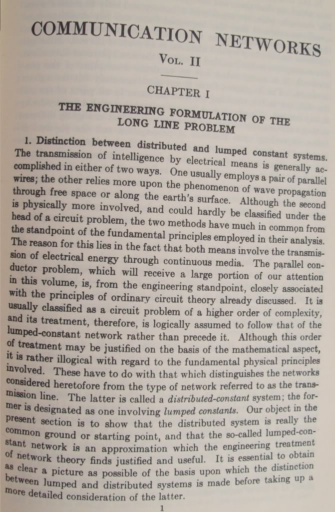
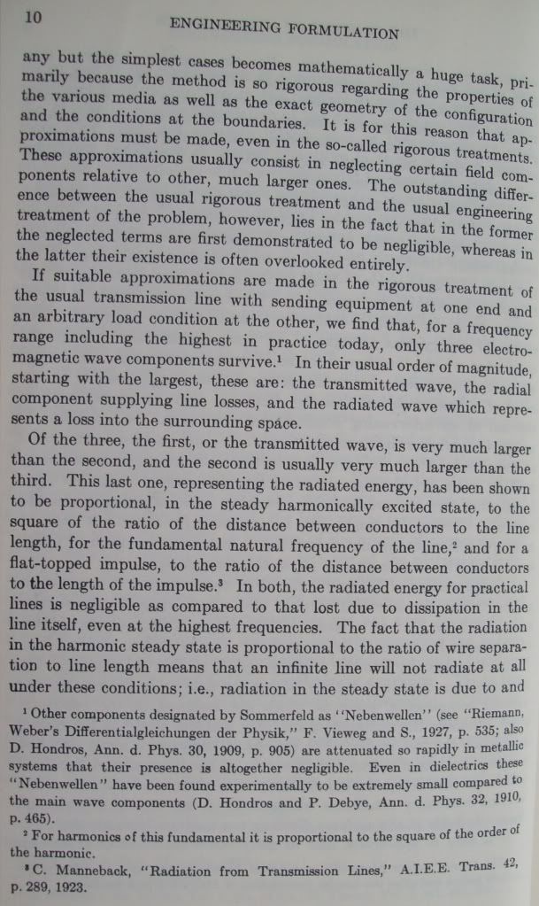
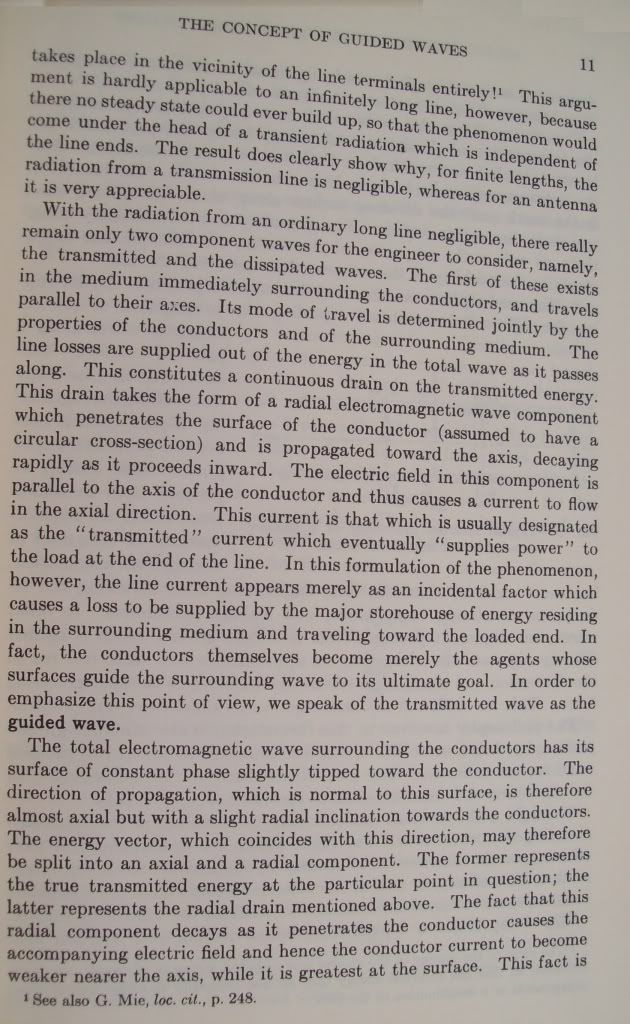
2) Notes on "Communications Networks" No 2, by Ernst Guillemen.
Guilllemen here draws ones attention to the fallacy of a lumped capacitor, or a lumped inductor. These represent only extreme conditions of the electric field of zero impedance or zero admittance respectively. Guillemen also points out that the established second order differential expression for electric waves are but a mere two terms of a much larger series of higher order terms. It seems now that a fourth order expression is required to advance in electrical situations such as multiple tuned networks and coiled windings with travelling and standing wave propagation around and within their structure. Guillemen also mentions a little about an unknown "surface wave", a "Nebewellen". Finally he discusses the paradox of an infinite two wire TEM line being incapable of any degree of leakage via electromagnetic radiation.
3) Considering the viewpoints of C.P. Steinmetz, and E.A. Guillemen, we fool ourselves into thinking that there is any real comprehension of electricity. This condition made it easy to prey to the grotesque perversions of physics to the electrical concept. It is more a real apprehension of electricity.
Thankyou for the Integratron detail.
Still some questions that only time will provide.
To help make it clearer-
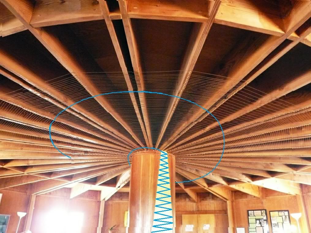
This is a rough idea of what the downstairs would look like. The Caduceus coils would be flat against the ceiling, and the column would have copper wires zig zagged across it:
Also the Dirod generators don't need to turn very fast to create tremendous potentials
How to post full size pictures on this forum? When I post from my computer I only get small size attachments. Also why is such a small size allowance for .jpg files? One more question, how can I post an email on the forum from my private correspondence?
When you click on "Share It" for an image it gives different links for thumbnails or full size etc. For the e-mail you can either copy and paste the text or press Print Screen and paste it into MS paint or whatever image software and upload the image.
This concludes the calculation of the important characteristics of the extra coil under study
Thank you Eric. I've just completed all the necessary secondary tests, the best I'll be able to do without rewinding it with thicker wire, and/or making a new frame. The preferred plan in that case is to make a bigger coil.
I'm now using a different measuring method so I can see the readings and change the frequency on the computer without getting close and affecting things:
As arranged
The frequency response graphs should now be within 0.3mV accuracy at each sample point and the written peak frequency values within 300 cycles/sec accuracy.
Used the condenser rings as suggested - upper ring connected to secondary neutral. The frame is only just big enough to set the rings at the correct distance. I think ideally the frame should be a little bigger.
The "final" results are as follows:
Secondary without condenser rings peak: 4126 kc
Secondary with condenser rings peak: 3670 kc
Extra Coil with 10pF peak: 2833.1 kc
Extra Coil with metallic connection peak: 2694.8 kc
How to post full size pictures on this forum? When I post from my computer I only get small size attachments. Also why is such a small size allowance for .jpg files? One more question, how can I post an email on the forum from my private correspondence?
Thankyou for the Integratron detail.
Still some questions that only time will provide.
Coil Capacitance Factor:
'Theory Of Wireless Power' Table 1, page 29 ~ 32:
OK, so when L=W, Factor 'p' is at a minimum and this is the ideal situation.
Explanation is on Page 29.
I had a problem with this but OK now.
Quote: 'Theory Of Wireless Power' Page 31:
"Windings on solid or continuous formers rather than spaced slender rods, as shown in figure (1), greatly retards wave propogation as indicated in equation (6), thereby seriously distorting the wave".
This is the only reason why I am not following other's ideas as to how these Tesla coils should be wound and also operate as I simply agree through empirical experiment.
Thanks.
Quotes from Steinmetz Paper: "Electrical Disturbances and the Nature of Electrical Energy", 1912
To all of us who are interested in the use of electric energy the nature and characteristics of electric energy are of importance; as on their understanding depends our success in the economic use of this energy, and our ability of guarding against the difficulties, troubles, and dangers which it may threaten when out of control.
_________________
We always speak of the phenomena of nature within the conception of energy and of matter. All we know of nature, all that our senses give us as information, is the effect of energy-energy which reaches our body through the eyes, through the ear, through the sense of touch; and if I were to make a definition of energy it would be "that thing which reacts on, and is perceived by, or can be perceived by, our senses." This is probably the most consistent definition of energy.
_________________
From the nature of the wave motion of light, we thus would have to conclude that the ether, through which the earth and all bodies rush with high velocity, and without appreciable friction, is a solid. This is physically impossible, and here we find a very common physiological phenomenon: if we attempt to carry any speculation or theory to its final and ultimate conclusion, we reach contra-indictions. This is not the the result if the nature of the phenomena, but is in the nature of our minds, which are finite and limited, and therefore fail when attempting to reason into the infinite.
_________________
depending on the nature of the gas: for example, the glow is pink with air, orange-yellow with nitrogen, green with mercuryvapor, etc. Going still to higher and higher vacua, the conductor which passes the current between the positive and negative terminal of the vacuum tube finally changes again and becomes a green discharge, which issues from the negative terminal in straight lines, like a beam of light, irrespective of where the positive terminal is located. It may not reach or come anywhere near the positive terminal, and if the positive terminal is located back of the negative terminal, the cathode ray, issuing from the latter, will really proceed away from the positive terminal.
_________________
The question then arises: What is the electron?By the derivation of its hypothetical existence, it is a form of matter, since its mass has been calculated by the action of forces on its mechanical momentum. It thus would be a new form of matter, a new chemical atom, a thousand times smaller than the hydrogen atom. It has been called "an atom of electricity." As "electricity" is a vague term without physical meaning, which has been loosely been used for "electric quantity" (and even "electric quantity" is a mere mathematical fiction, a component factor of electrical energy) no objection exists to giving the name "electricity" to this new hypothetical form of matter, represented by the electron. It naturally does not explain anything: the electron certainly is not electric quantity, nor is it electric energy, but it may be defined as that form of matter which is the carrier of electric energy. Then, however, the electron in its definition comes rather close to the hypothetical ether atom, which is the carrier of radiant energy, that is, the carrier of the electric wave in space.
_________________
These and other numerous contra-indictions to which the conception of the ionic theory leads, obviously do not mean that the ionic theory is fundamentally wrong in principle: we have also seen that the wave theory of radiation, in the properties of the luminiferous ether, lead to attributes that are contraindictory and thereby impossible. We find the same thing in all theories- the chemical, the thermodynamic, etc. It simply means thtat our present formulation of the ionic theory, of the electromagnetic wave theory, and of all other theories are very far from final correctness, but are at best only very crude conceptions of the nature of things, which will have to be modified again and again with our increasing knowledge before we can expect to reach a moderately rational conception of nature's laws and phenomena, if we ever arrive there.
Integratron:
What did the original ceiling coil look like and what was wound around the central post and could we assume this to be similar to a Lakhovsky type device?
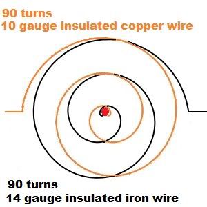
The original ceiling coil was the two iron and copper spiral Caduceus coils as depicted in the diagram:
Don't have any original pictures of the Caduceus sorry. Not similar to a Lakhovsky device. They are not antennas, they are a transformer. Also they are not log periodic, they are normal spirals. As said previously, copper wire was wound in a zig-zag pattern around the pegs on each side of the central column. The pegs you can see were the form for the coil.
Electrostatic field from the Cyclotron/Dirod Generator into the Aluminium roofing of the dome and a Lakhovsky multi wave from the floor or first floor ceiling and the central post a Lakhovsky/Tesla Primary?
Yes the electrostatic field charges the aluminum roofing of the dome. Then the Caduceus transformer on the ceiling, and the zig zag copper coils on the column forming a triangle capacitance that capacitively couples with something on the inside of the column
1) From Table 2 of the Theory of Wireless Power, for an aspect ratio of 10 percent, the free space coil velocity effective is
78%
2) The actual frequency is given as
1188 Kilocycles/sec
The luminal frequency is derived as
1856 Kilocycles/sec
And hence the actual velocity effective is given
64% luminal velocity
Note, 63.7% is one over the value of Pi over two
3) From table 1 of the Theory of Wireless Power for a 62 cm diameter coil is given as
60 picoFarads
This is the free space capacitance of the coil.
The actual capacitance is derived from the square of the ratio of free space to actual velocities of this secondary coil.
Ratio of Velocities
126%
Squared giving
1.58 numeric
Capacitance, actual
95 picoFarads
4) Tabulating this data
Luminal velocity
100%
Free space velocity
78%
Actual Velocity
64%
Free Space Capacitance
60 picoFarads
Actual Capacitance 95 picoFarads
Conclusion, coil form and stray lead capacitance add 35 picoFarad of capacitance burden.
Nhopa #704 (II)
The natural, or characteristic impedance, of this secondary coil as a transmission network is derived.
1) By Wheelers formula in the Theory of Wireless Power the total magnetic inductance is given as
444 microHenries
The actual capacitance been given as
95 picoFarads
2) Determining the effective values of inductance and capacitance resulting from the Cosine and Sine quarter wave space distributions the following are derived
By Steinmetz method it is, the effective inductance
283 microHenry
The effective capacitance
60.5 picoFarad
And the effective values from the Miller method it is, the effective inductance
222 microHenry
The effective capacitance
77.1 picoFarad
3) The natural impedance is defined as the square root of the ratio of the inductance to the capacitance, giving
Steinmetz, 2200 Ohm
Miller, 1700 Ohm
4) Hence the primary transmission factors are determined for the secondary coil
v, propagation constant
64%
Z, the natural impedance
1700, or 2200 Ohm
1950 Ohm averaged
Nhopa #704 (III)
It seems that your test coil is too close to secondary, back it away instead of using a ballast resistor. Then look for distance to give the sharpest curve. The magnification factor is the inverse of the bandwidth between the 70.7% down points on each side of the curve.
ALSO NOTE EVERYONE!
I cannot see attachments in coffee shop, I cannot! Post full size pictures then I can respond. Remember also that this provides visual entertainment to the person who is working his/her computer. Remember the coffee shop customer is often a cowboy, or a foreign hiker from France or Italy, they think a Volt is a car by Chevy.
Finally from the Geometric Algebra, Dr Green, and Nhopa material the secondary and extra coils are quantified. It now is a simple matter for any competent person to design a coil for any desired frequency. It is now engineer-able.
Secondary tuning test results. Meter connected to end ring
Using 20 Turn Secondary calculations
F = 1188000 cycles/sec
Height = 6cm
Diameter = 62cm
Number of turns = 20
Calculated wire length = 40.4 meters
Wire used 17 AWG
l
Variable condenser was not used used with secondary for any of the following tests.
Test Coil = 1 turn of 1.2 mm dia insulated wire
Setup as per E.P. Dollard and dr-Green
Notes
Wire length from top ring to meter approx 30cm
Wire length from meter to beer can approx 15cm
Beer can = 500ml
Function generator Wavetek FG2A
Frequency counter Wavetek UC10A
uA meter 100-0-100uA
On the INTERNET I was reading that since the output impedance of the the Function generator (Osc) is only 50 Ohms and that will limit the ability to measure the natural frequency of the coil, therefore, I have added in series with the test coil a 10K resistor. I ran the tests both using this resistor and without it. With the resistor I got much sharper response curves. Please advise If I really need to use the resistor.
Attached are the hand drawn frequency curves and picture of the test set-up.
Next I will test the secondary with the condenser ring on top.
It seems there is very limited amount of space allowed to post pictures. I can't attach the test set-up but at least I could attach test1 and test2 results in the next two postings.
Last edited by Nhopa; 06-16-2012, 03:18 PM.
Reason: To remove "invalid" attachments


Leave a comment: