Announcement

Collapse
No announcement yet.

My Motors got me to Tap into Radiant Energy

Collapse
X
 
  • Filter
  • Time
  • Show
Clear All
new posts

  • Ufopolitics
    replied
    Primary-secondary

    Originally posted by iankoglin View Post
    G'Day UFO,Dana
    thanks for your input
    @ UFO
    When I wire each strand should I wire them as a bifilar that is each series of layers making up the primary coil and the Secondary coil be made of wired mixed every second layer or contiguous layers so that the primary is first coil only, then the secondary in series laying all by itself on top of the primary?

    [IMG][/IMG]
    Regards Kogs
    Hello Ian,

    The Primary should be wired as a Multifilar , meaning all strands together, do not need to twist them, just straight but keeping them together as you wire, since they tend to spread apart (not good).

    Now Radiant transfers from OUTSIDE-IN, and NOT good, very weak when secondary is located in the outer embodiment of Coil, or on top of Primary. So, my best recommend is to wire first your secondary right next to coil core, then the Primary above it.

    ...the Secondary coil be made of wired mixed every second layer or contiguous layers so that the primary is first coil only, then the secondary in series laying all by itself on top of the primary?
    So, No Ian...it is the "other way around"...Secondary FIRST, then Primary to be at the Outer Coil Embodiment.

    And just forget about Option Two (2)...like Dana said...it kills, cancel EM Field between them, big ZERO, no matter how you've wound the coil...And the Magnetic Field is what We should care the most here!!


    Regards


    Ufopolitics

    Leave a comment:


  • larryross
    replied
    Kogs
    If you really wired it as pictured where with every layer you started at the top with each layer and wound the same direction then you would wire as option 1, but if you wound a normal wind that goes from top to bottom then from bottom to top as in the attached picture then you would need to wire as option 2.
    When I did my coils for my reciprocating electric motor I did quadfilar by winding 4 wires simultaneously from top to bottom then from bottom to top (believe me it isn't easy to do) always winding the same direction. When finished I had 4 wires side by side at the beginning of the wind and 4 at the end and it was easy to figure out how to connect them for series or parallel.

    Hope this helps
    Larry
    Attached Files
    Last edited by larryross; 06-22-2012, 04:27 AM.

    Leave a comment:


  • iankoglin
    replied
    Originally posted by Ufopolitics View Post
    Hello Ian Koglin,

    I am glad you asked me before going on...
    Definitively would be Option 1


    In Option 2 You are right, you are going against direction in each one...therefore, they will cancel magnetic fields to a big zero...no cigar, no joy.

    You have to think as if you were winding continuously as if all strands were just one wire, and without stopping...then you will choose number one option.

    But now that you have shown this graphics...I am wondering how did you measured the resistance in the whole Primary Strands originally?...

    On the other hand, you have said you wanted really a great result, great output...and honestly, when you said all this strands measured 1.5 Ohms, I thought they were all in parallel connection at the time you measure them...

    Now, If you really want a great output...They all -IN PRIMARY- should be connected in parallel, meaning all starting terminals together as one ...and all ends together...making it a "Three Filar Coil"...BUT!!...THEY MUST BE ABOVE ONE (1) OHM!!!

    Now I need to know what your resistance would be once connected as option one or two...or maybe that is the way you have measured them before...You tell me.

    Both options, one (1) and two (2) should read same resistance...but not if connected in parallel.

    The fact of using Option One and not in parallel is NOT going to blow anything in your circuit...it is just not going to be such an outstanding output, that's all.

    Let me know


    Regards


    Ufopolitics
    G'Day UFO,Dana
    thanks for your input
    @ UFO
    When I wire each strand should I wire them as a bifilar that is each series of layers making up the primary coil and the Secondary coil be made of wired mixed every second layer or contiguous layers so that the primary is first coil only, then the secondary in series laying all by itself on top of the primary?

    [IMG][/IMG]
    Regards Kogs

    Leave a comment:


  • Ufopolitics
    replied
    Hello Iankoglin

    Originally posted by iankoglin View Post
    G'Day UFO
    I have been seriously thinking when you said I hope you are following same winding direction in all strands.

    When I wound my coil looking from the top I wound all the strands in a clockwise direction, each strand was a separate strand with a pigtail each end as shown here


    and here is the finished 8 layered coil


    The question NOW Which way to connect the strands?
    Option 1 Series wound current in each strand runs in same direction I think
    [IMG][/IMG]

    Option 2 Wound in series current in each strand runs in opposite direction I think
    [IMG][/IMG]

    I had and still have wound connections as per Option 2

    Please advise which is CORRECT It is easy for me to adjust

    Kindest Regards


    Hello Ian Koglin,

    I am glad you asked me before going on...
    Definitively would be Option 1


    In Option 2 You are right, you are going against direction in each one...therefore, they will cancel magnetic fields to a big zero...no cigar, no joy.

    You have to think as if you were winding continuously as if all strands were just one wire, and without stopping...then you will choose number one option.

    But now that you have shown this graphics...I am wondering how did you measured the resistance in the whole Primary Strands originally?...

    On the other hand, you have said you wanted really a great result, great output...and honestly, when you said all this strands measured 1.5 Ohms, I thought they were all in parallel connection at the time you measure them...

    Now, If you really want a great output...They all -IN PRIMARY- should be connected in parallel, meaning all starting terminals together as one ...and all ends together...making it a "Three Filar Coil"...BUT!!...THEY MUST BE ABOVE ONE (1) OHM!!!

    Now I need to know what your resistance would be once connected as option one or two...or maybe that is the way you have measured them before...You tell me.

    Both options, one (1) and two (2) should read same resistance...but not if connected in parallel.

    The fact of using Option One and not in parallel is NOT going to blow anything in your circuit...it is just not going to be such an outstanding output, that's all.

    Let me know


    Regards


    Ufopolitics

    Leave a comment:


  • prochiro
    replied
    Coil

    Kogs
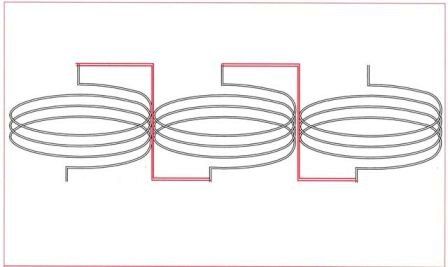
    In option 2, when you double back the second wire with current going the opposite way as wire 1, you are killing with the second wire what you created in the first. Option one is the correct method for series winding. Wires are connected like ----- start-end-start-end-start-end so current always goes in the same direction.
    Dana

    Leave a comment:


  • iankoglin
    replied
    Winding Direction

    Originally posted by Ufopolitics View Post
    Hello Kogs,

    The one with 1.5 Ohms should work great as a primary.
    Now you've said they are connected in series, but, I hope you are following same winding direction in all strands.
    The 0.5 Ohms should work as secondary, not as primary!...However, it will not give you higher outputs than primary.
    Glad you got an IR Thermometer!

    Good testing


    Regards

    Ufopolitics
    G'Day UFO
    I have been seriously thinking when you said I hope you are following same winding direction in all strands.

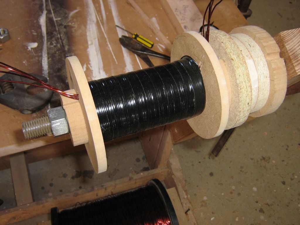
    When I wound my coil looking from the top I wound all the strands in a clockwise direction, each strand was a separate strand with a pigtail each end as shown here


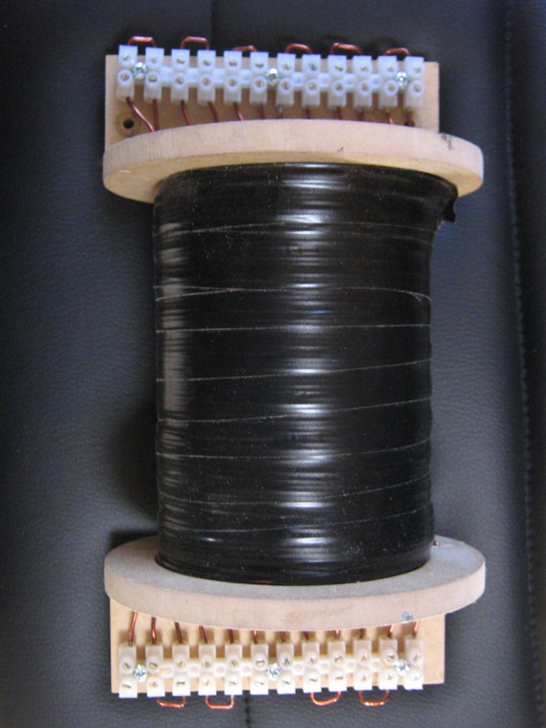
    and here is the finished 8 layered coil


    The question NOW Which way to connect the strands?
    Option 1 Series wound current in each strand runs in same direction I think
    [IMG][/IMG]

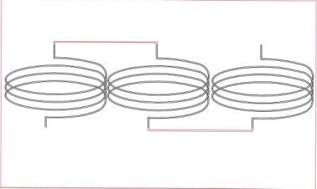
    Option 2 Wound in series current in each strand runs in opposite direction I think
    [IMG][/IMG]

    I had and still have wound connections as per Option 2

    Please advise which is CORRECT It is easy for me to adjust

    Kindest Regards

    Leave a comment:


  • larryross
    replied
    Originally posted by JohnStone View Post
    If we drive a gate (voltage) or base (current) more than necessary they perform with slower switching. Transistors suffer of this effect more than FETs.
    It is no necessity to drive FETs higher than their optimum voltage vs. current. There are some tricks out there in order kick the gate with a short higher voltge pulse in order to get the required charge faster into the gate. But that is another story.
    The maximum voltage at gate shall not be confused with the necessary gate voltage for minimum RDS ON
    For 2SK2837 the satisfied test condition is 10V / 10A but typically it will be fully switched on at 6V.
    Below 4V it is securely switched off.

    I prepared my driver circuit to perform up to 15V.
    Thanks John and kEhYo77
    I will certainly give this a try before I go and rebuild. It seems that turning on a FET was more complex than that. It seems like I remember there was a linear correlation between the % of +- Vgate spec and the % turned on. Another problem of being old and not keeping in the game.

    Regards
    Larry
    Last edited by larryross; 06-22-2012, 01:44 AM.

    Leave a comment:


  • torpex
    replied
    Hi all

    I played with the new LM339 circuit in battery charger mode:


    Charge time: 4 hours
    Disconnect when it reached 15.22v
    Seems fully charged, disconnected after 2 hours: 12.85v
    Curiosity in ammeters: 0.9A Input and 1.10A charger


    Leave a comment:


  • JohnStone
    replied
    Originally posted by larryross View Post
    ...Though there are many newer devices that show +- 30 VGS, one that isn't close to the trade wouldn't know it....
    If we drive a gate (voltage) or base (current) more than necessary they perform with slower switching. Transistors suffer of this effect more than FETs.
    It is no necessity to drive FETs higher than their optimum voltage vs. current. There are some tricks out there in order kick the gate with a short higher voltge pulse in order to get the required charge faster into the gate. But that is another story.
    The maximum voltage at gate shall not be confused with the necessary gate voltage for minimum RDS ON
    For 2SK2837 the satisfied test condition is 10V / 10A but typically it will be fully switched on at 6V.
    Below 4V it is securely switched off.

    I prepared my driver circuit to perform up to 15V.
    Last edited by JohnStone; 06-21-2012, 08:54 PM.

    Leave a comment:


  • codeboundfuture
    replied
    Re-reading the thread, lots of good information from everyone.

    best wishes,
    matt

    Leave a comment:


  • larryross
    replied
    Originally posted by kEhYo77 View Post
    @ Larry, yep I'm in my 30ies if You can call it young
    Maybe there is something I said? Don't know, English is my secondary language so there might be some funny errors.

    For the 2SK2837 fet specified 8V for gate drive is enough looking at the chart from the datasheet.
    kEhYo77
    Ya... when you are in your late 60's, 30ish is very young... I was your age or older when you were borne. I used to think 70 was old, but it doesn't seem so old any more.
    Yes it was something you said, this was the hint "For most of mosfets the gate drive is 10V it even goes down to 5V for logic level fets". Though there are many newer devices that show +- 30 VGS, one that isn't close to the trade wouldn't know it.
    About my FET, I wasn't to careful about reading the charts, guess I will have to go and recheck it. You are saying that 8 volts will saturate the FET so I can get full on for nice 36V square pulse out? Good hope you are right.

    Larry

    Leave a comment:


  • kEhYo77
    replied
    @ Larry, yep I'm in my 30ies if You can call it young
    Maybe there is something I said? Don't know, English is my secondary language so there might be some funny errors.

    For the 2SK2837 fet specified 8V for gate drive is enough looking at the chart from the datasheet.

    Leave a comment:


  • larryross
    replied
    What is the device number of your ultra fast 1200V IGBT?

    Leave a comment:


  • Ufopolitics
    replied
    Sometimes the simplest things go by without noticing them...

    I wanted to share something with you all...

    It is not a secret, most of Us know it...

    Most of times We complicate things...we try to make them so clever, thinking they will perform much better...that we distract completely from noticing the very original and very simple roots of everything around Us...

    And relating to my set up, I will explain...

    The 555 chip, working in Astable mode, is the simplest and cheaper circuit you guys could build...is everywhere on the net...and it works as I have repeated here to exhaustion, as a matter of fact, I have wrote that I have not made the other great circuits yet...However, most of you try to go FIRST, the clever and complicated ways...before trying a nickel and dimes circuit that is proven to work, at least to show my point here...
    The video I posted above proofs that is so simple!
    And please do not take me wrong, I do agree with improving a circuit, to make it excellent in performance and more adjusting parameters...that is just awesome...BUT...Why don't try first with the simplest 555 chip??!!...and THEN, move on to complicated set-ups.

    The same thing, exactly the same, has happened with Electrodynamics...and you all will realize it when I post the blue prints...The principle, the basics are sooo simple!!, that I know you will laugh, like I did once I got them running....and ask yourselves...Why didn't I think of it before!!??...Well, we were all very busy complicating things...

    This includes all of Us...plus all generations in line...piled one after the other...for over 130 years.

    And I can NOT include everybody here, speaking like no one has done it...There are many who have done it...but they either sold his souls to Money and Greed...or they silenced them all this time...

    I hope We all could teach a lesson to ourselves for other generations to come not to follow this "Negative to Evolution" process...


    Regards to all


    Ufopolitics

    Leave a comment:


  • larryross
    replied
    Originally posted by kEhYo77 View Post
    Hi Larry.
    It is strange to see 30V requirement for the gate.
    What kind of fets did You choose?!?
    You must be relatively young.

    For most of mosfets the gate drive is 10V it even goes down to 5V for logic level fets and it usually goes a bit higher for IGBTs: up to 15V.
    From the datasheet you will have to examine current/voltage curves for different gate voltages. You'll see that one 12 battery is good enough for driving this setup.
    But let nothing stop you from applying those 36V to the coil
    To get good and strong response from the ambient in the form of a BEMF it is required to go higher in voltage/current and shorter in pulse width. Ismael Aviso says that from his experience the pulse should be from 0,02 to 0,05 of a second.
    Frequency of optimal operation depends on the coil. You can easily expect those oscillations go high in AC voltage. Times TEN! For My coil if I pulse it with 30V DC I get 300V AC!
    Yes I understand the voltage can be raised through transformer, but the current goes down by the same times ten. Unless radiant is different... that, I haven't been able to experiment with to date. So then you end up with high voltage, high frequency, low current that I haven't seen any mention of being able to do any conversions of yet. To date the only things I have seen powered by the device that is truly bringing in radiant are high voltage high frequency very low current devices. I know there is much more to learn, but I can't of course speak to those yet.

    What I do is I pulse the coil manually to do a quick test and watch the scope for response. The ringing of the coil in HF diminishes to zero after a certain period of time. This period is the minimum working frequency.

    So my advice, if there is a scope nearby, is to check the coil and start slowly, just like Ufopolitics said, but to start from this calculated frequency minimum and go up from there.
    This way the risk of burnt fets is less. Where for instance at very low frequency your pulse width can be waaay to wide...

    Any pulse generator retaining pulse width independently from frequency changes would be more helpful.

    Cheers
    Peter

    P.S. My ultra fast 1200V IGBTs and 600V Schottky diodes for the ultra fast forward bridge arrive tomorrow!
    Can't wait...

    Hi kEhYo77
    I guess you might be new to the thread and haven't read all the previous pages as my choice of the Toshiba 2SK2837 FET was posted and discussed a few pages back. I chose it (there may be better choices) because of the price of $1.80 each compared to $5.00 to $6.00 for the recommended plus shipping. Second reason is the fact that the power dissipation is higher than that of the recommended FET (many were having problems blowing their FETs even with the relatively low current requirements) and the max volts were higher and the max current was higher too. If I need more power dissipation I could go with the FDL100N50F which can dissipate 2500W.
    So with a little luck and memory recall from many years back I should be able to make it work.
    My oscillator circuit has separate frequency and duty cycle adjustments and one can be changed without effecting the other + it also has a complimentary output.

    Cheers
    Larry

    Leave a comment:

Working...
X