

-
This blew my mind when I started mapping it, its a sink, this is it,just have to build it and figure out how to power it.Leave a comment:
-
this is some mighty inspiration.....as far as i can tell, you have the fractal shape correct
and perpendicular coils are nothing more than vertical vs horizontal...two opposites
or if you prefer 6 vs 9Leave a comment:
-
we need to take this principle and run with itWalter Ford�s High-powered Crystal Set
In the 1961 edition of the Electronics Experimenter�s Handbook, there is an interesting circuit from Walter B. Ford for a high-power crystal set capable of powering a 2.5-inch loudspeaker:
He says: Here�s a pint-sized crystal radio with enough power to drive a 2.5� speaker. This little unit's selectivity is far better than you would expect to find in a crystal re�ceiver and volume is equal to that obtained with sets using a transistor. No external power source is required.
The unusual selectivity of this radio is due to its special double-tuned circuit. A pair of diodes connected as a voltage-doubler provides the extra power to operate the small speaker. An output jack is provided for headphone listening and for connecting the set to an amplifier.
Construction: The model was built on a 2.5� x 4.5" wooden chassis with a 3.5" x 4.5� metal front panel. However, size is not critical, and other materials can be substi�tuted if desired.
Two standard ferrite loopsticks, L2 and L3, are used. Both must be modified by the addition of a second winding. L1 and L4, respectively. Each of the added windings consists of 22 turns of No. 24 cotton-covered wire wound on a small cardboard tube as shown in the picture. (Actually, any wire size from No. 22 to No. 28 with cotton or enamel insulation will do the job).
The diameter of the cardboard tube should be slightly larger than L2 and L3 so that L1 and L4 will slip overL2 and L3 easily.
Resistor R1 is used only for feeding the set into an amplifier; it should be omitted for both earphone and loudspeaker opera�tion. Trimmer capacitor C2 should be sol�dered across the stator terminals of two-gang variable capacitor C1a/C1b as shown. The speaker and output transformer can be mounted wherever convenient.
If a metal chassis is used, then be sure to insulate the aerial and earth connection sockets from the chassis. When all of the parts have been mounted on the chassis, wire them together follow�ing the schematic and pictorial diagrams. Be sure that diodes D1 and D2 and capaci�tors C3 and C4 are connected correctly, paying attention to their polarity.
While this is interesting, what appears to be a key factor is contained in the drawings, where he states that the only important thing is that it is essential for the two sets of coils to be mounted perpendicular to each other:
Last edited by Dave45; 12-21-2011, 12:56 AM.Leave a comment:
-
Im going to continue to work on the transformer, but when money permits I am going to build this
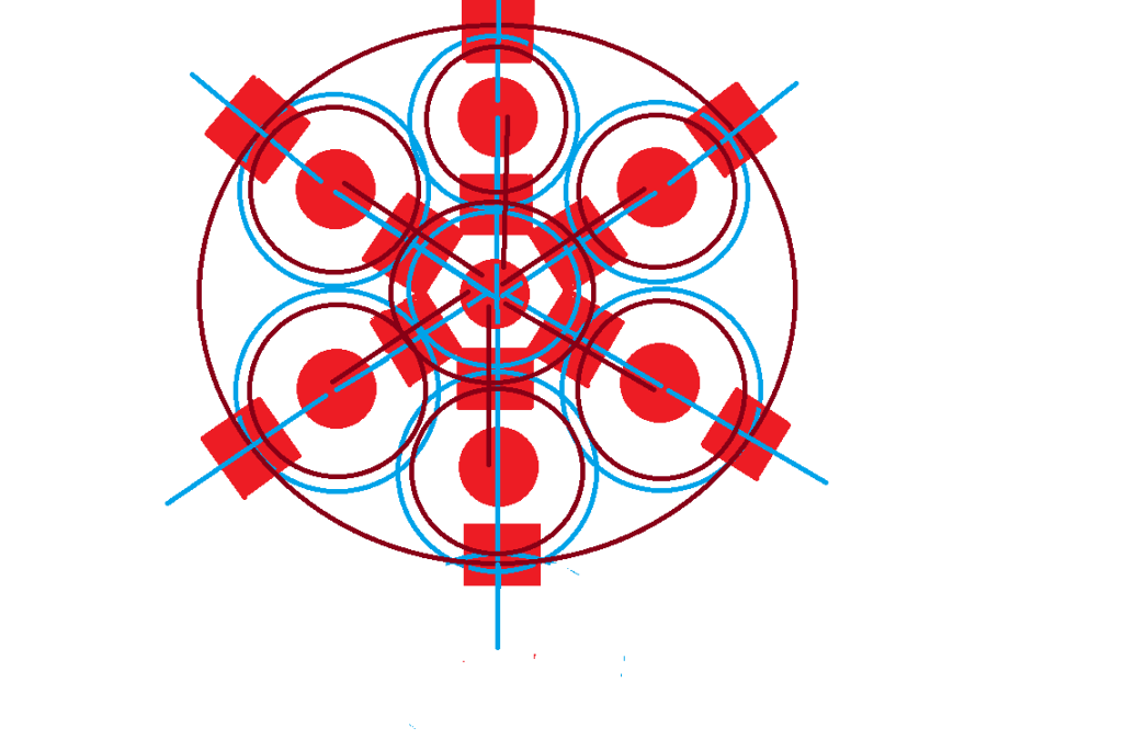
there is free energy here.Leave a comment:
-
I think these would have to be air cored coils, if we run the electric field in iron cores they will heat up, or I was thinking I have some hollow ferrite cores that would be interesting to try.Leave a comment:
-
The perpendicular coils has me curious
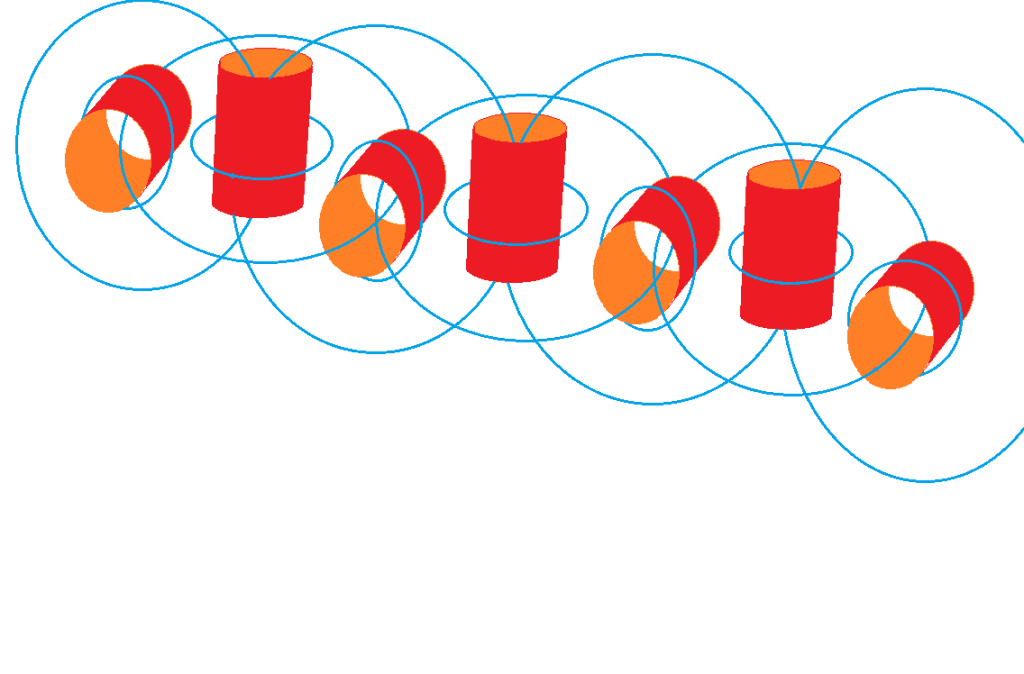
we know by looking at the alternator
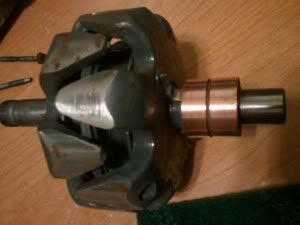
that when the magnetic field and the electric field are moved into the same plane we get extra energy
so
Leave a comment:
-
I was mia for a couple of days,
I decided to map the fields and this is what I came up with for a six sided magnet motor
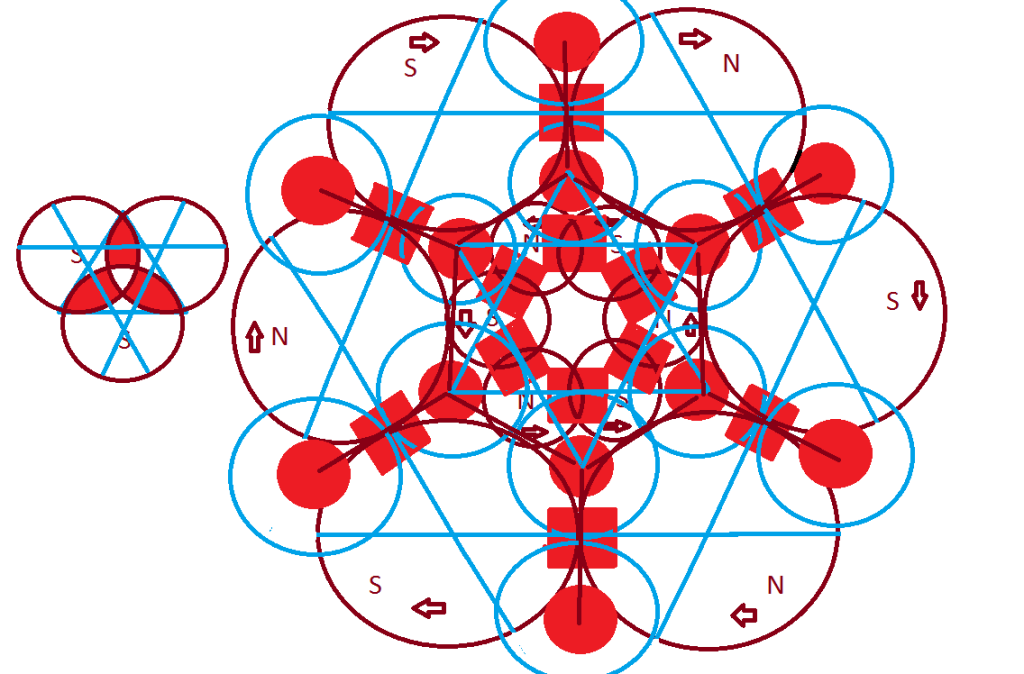
but I was thinking about the crystal radio that powers itself and the perpendicular coils that are a requirement for it to work, I was thinking how could we boost it, this is what I came up with
notice the center coil the receiving coil
Leave a comment:
-
now that might be the problem with banding material.
i know i have see 3/4 square hole bobbins but can't remember were.
MartinLeave a comment:
-
I think it would work for testing, money is tight this time of year, should be able to get some from the lumber yard, winding coils is gonna be a pain and slow, I wonder could it be threaded through bobbins.Leave a comment:
-
wire will work as well and i think the banding comes with some oiling on it for rust but it is easy to lacqer with a spray can as well when winding a drop of superglue can help hold it in place as well
this was what i was thinking of doing for simplicity.
MartinLeave a comment:
-
Great idea Martin I think banding strap should work. Sourcing material is a pain you can get it from China by the ton we dont make anything anymore.
Leave a comment:
-
The magnetic permeability of the core material affects the efficiency of transformer and selecting the proper core material can enhance the total system efficiency. The following attached information may help
RegardsLeave a comment:
-
actually dave i was thinking about the vid and what i have seen about the flynn paralell path but instead of wire i was going to use steel palet banding strap 3/4 wide and then some 3/4 neo mags.
MartinLeave a comment:

Leave a comment: