-
No ground wire needed, connect the ends of the primary's to the beginnings of the secondary's. -
You dont have to use high voltage, SM did it with a nine volt battery and flip flop circuit, of course he used a toroid as well, but he had heat problems.
I believe it can be done using the Don Smith air coils, the higher the input voltage the more power out.Leave a comment:
-
We are powering a magnetic system from the center out in both directions without flipping the dipole
powering it from the bloch wall, equatorial plane
it will workLeave a comment:
-
This is it, this is what I have been looking for, for four years.
Time to build.
daveLeave a comment:
-
each coil puts out a bidirectional field one coil puts out cw and ccw fields
the other coil will put out ccw and cw fields
the shorted coils on each side will catch the bemf of the other, the secondarys will catch the femf of each coil one will be voltage the other current.
its the direction of the applied current through the coils that makes the difference.Last edited by Dave45; 08-18-2012, 10:45 AM.Leave a comment:
-
wind one coil set on one half of a toroid the other on the other half of the toroid-TPULeave a comment:
-
I think I have found what I was looking for, about six months ago I wound a cw winding and a ccw winding on an iron core if both coils are powered from the inside wires the pole orientation does not change
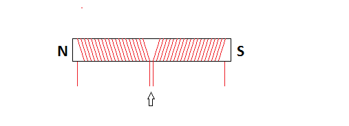
this means current is the bemf on one coil and voltage is the bemf on the other, this is why SM used a bifilar winding and flipflop circuit.
wind one coil cw trifilar wind the other ccw trifilar use first winding as primary on each coil next winding as per leedskalnin shorted coils last windings are the secondary's that you will draw energy from one coil will put out pure voltage the other pure current use a flipflop circuit to drive the coils out of phase.
Build the system in a vertical position
This high voltage driver should work
DIY Homemade Ignition Coil Driver - RMCyberneticsLeave a comment:
-
My last coil design should give a small increase in current but is not what we are looking for, the cap after the primary will send current back through the primary changing its polarity and current will be induced into the first secondary because of the spark gap but we have used precious energy that should have been collected in the first pass through the coil, will not go ou.
I will continue to study the problem.
The current needs to be stopped after the primary, this way the forward emf will be induced into the secondary instead of following the applied current back to the source.
daveLeave a comment:
-
You guy's are the giants you and every experimenter before you that passed his knowledge ahead of himself, I have studied your work and was amazed.
Math is flawed in that if you don't know the very basic reaction you cannot give a true mathematical relationship to a linear world.
Take care
And may God bless you
daveLeave a comment:
-
I need to quit refering to the currents side of the emf as bemf, actually it is forward emf, I used the bemf as a way to express the field is outside and collapsing into the coils.
We have bemf which is high voltage and femf which is high current, by stopping the flow of current after the primary we give the femf no alternative but to collapse into the secondary, as per Don Smiths cw and ccw secondary coils.
I feel like the boy that cried wolf, I have expressed so many idea's here, but it has been a learning experience for me.
daveLeave a comment:
-
For some reason I cant edit my last post.
Anyway I believe the reason we are not getting current in our devices is because the bidirectional fields are sending the current bemf into the source instead of our secondary's, Tom Beardon's idea would surely help but we have to isolate the primary on both ends as well.
Voltage bemf is easy because it runs counter to the direction of the applied current but the current bemf is naturally attracted to the current moving in the wire and it is moving with the direction of the applied current so it flows back into the primary back to source.
Guys if you pay attention to this one detail and build your devices to catch this field things will change drastically.Leave a comment:
-
The Tom Bearden Website
A very interesting article by Tom Bearden
I wonder could we use iron wire as our primary and copper wire in our secondary's, it would probably heat up, but his theory makes sense, I wonder brass wire maybe or maybe acid treated copper wire.Leave a comment:
-
A gas generator's coils puts out a varied frequency depending on the rpm of the armature, it would seem the circuitry could be used to get the frequency of our devices back to 60 hz.Leave a comment:
-
The coil is changing the polarity and works in conjunction with the capacitor.
A question, are voltage and amperage running in opposite directions through a circuit (wire).Leave a comment:

Leave a comment: