This forum is preserved as a permanent archive. The community continues at eMedia Press.

Announcement

Collapse
No announcement yet.

3D electromagnetic field

Collapse
X
 
  • Filter
  • Time
  • Show
Clear All
new posts

  • MonsieurM
    replied
    this is an example posted by Dave45 of the Smith/Caduceus Coil used to levitate at high voltage

    induction heater levitation melting aluminum - YouTube

    Please note the movement evolution of the aluminum piece

    Leave a comment:


  • Xenomorph
    replied
    I actually went ahead and made an experiment according to what Nunnerley said about the antiphase coils.
    Two coils wound in opposite directions on a ferrite rod.
    In keeping with the Hz Theory promoted by the company EH-antenna.com, i have even turned the coil 90 degrees to the magnetic field of the rotor magnets as depicted by the Hz aerial illustration.

    Loading the coils (just shorting the ends) creates a normal lenz drag (rotor slow down). An indicator for current flowing in the coils.
    Obviously this set-up (as it is) can not pick up ONLY a Hz field and NOT turn it into electron current.
    So i don't know how to interpret this.
    Nunnerley repeatedly states that he sees this phenomenon present in the Muller generator. I just can say that i have never seen 90 degrees turned generator coils in one.

    Chances are that the "sending" side of the rotor would be required to undergo a "modification" for this to work as well, which would again represent a deviation from the Muller design.
    Just wanted to share this experimental results and looking forward to Mike one day presenting an experimental set-up that properly reflects how he sees this working.

    Leave a comment:


  • jerdee
    replied
    Inductor acting mostly as capacitance

    Originally posted by Michael John Nunnerley View Post
    Sorry for the bad explination of the coil setup, I will try again

    Wind a bifiler coil, the start of one wire will be 1s and the other 2s, the finish ends will be 1f and 2f. Now connect 1s and 1f together and 2s and 2f together. what you have made is two coils with a capacitance built in joining them together. We do not want an antenna, we want a magnetic coil with a vortex field and this is one way to do it.

    If I have time I will wind one. Trying to finish my new lab and office.

    Remember that the only connection of one coil to the other is one of capacitance, it is an LC circuit with low R depending on the wire used.

    Mike
    So basically this coil arrangement will force the current to lead with little voltage due to the coil acting mostly as capacitance. With low R, essentially creating a low ESR to allow the gauss field to fully develop fast! Then capitalize on the magnetic field generated for standard generator purposes?

    It's as if we are using inductor as a capacitor that generates a strong gauss field instead of storing the magnetic field.

    Just gathering thoughts on this coil arrangement....

    Jeremy

    Leave a comment:


  • mk1
    replied
    Originally posted by tutanka View Post
    Caduceus coil = Tesla coil

    Nothing of new...

    Sorry but that is wrong , On the Tesla coil the second wind goes in the same direction as the first , on the Caduceus the second wind goes in the opposite direction ...

    Leave a comment:


  • MonsieurM
    replied
    Originally posted by Michael John Nunnerley View Post

    If you look at the paper that I posted you will see that a Hz field WILL ONLY COMMUNICATE WITH ANOTHER Hz FIELD. Now how do we create an Hz field on the rotor so as the stator coil will communicate with the rotor "coil or magnet setup".


    Mike
    all optimally mated symmetries fractal shapes, can lock into spatial resonance configurations that maximize their interaction
    Access : Solid-state physics: Golden ratio seen in a magnet : Nature

    Last edited by MonsieurM; 08-11-2011, 04:49 PM.

    Leave a comment:


  • Xenomorph
    replied
    Originally posted by Michael John Nunnerley View Post
    I am not going to make things easy, you have to work for it like I had to.
    Pretty much exactly the same words can be found in various threads
    coming from various self-proclaimed prophets of overunity veiling themselves behind vague statements.
    Okay, take that as no offense. Nothing more to do than respect your choice
    of being secretive. I will certainly take you by the word and re-read the paper.
    Good Luck

    Leave a comment:


  • Michael John Nunnerley
    replied
    Originally posted by Xenomorph View Post
    If this relates to #33 then how are you gonna connect the shorted coils to the dump cap?

    I have made a capacitive generator coil before, but you can't extract any current from it. There is not enough charge, the capacity is in the low nanofarad region. To increase it you would have to wind a veeery big coil with lots of area. Too big to fit into a small Muller.

    Read here:
    Standing Waves in Generators
    Hi there, this is a quote from you, I do not frequent the other forum

    It is sadly like Bolt sais, you need to be an expert in RF tuning to get this right.
    I am sure that once you saw the effect, you could go from there.

    I am an expert in RF.

    If you look at the paper that I posted you will see that a Hz field WILL ONLY COMMUNICATE WITH ANOTHER Hz FIELD. Now how do we create an Hz field on the rotor so as the stator coil will communicate with the rotor "coil or magnet setup".

    I am not going to make things easy, you have to work for it like I had to. Read that paper over and over again and apply what you see to a magnetic field that communicates between two or MORE points, but not as an antenna, but the principles are the same, just have to impliment them in a different way.


    Another clue, look up loop antennas and see how they are connected and also see how much power is in the capacitance of the main loop, it is posible 2000v @ 2amps, 4KW without trying.

    Mike

    Leave a comment:


  • MonsieurM
    replied
    FYI

    Access : Solid-state physics: Golden ratio seen in a magnet : Nature

    Leave a comment:


  • Xenomorph
    replied
    Originally posted by Michael John Nunnerley View Post
    Sorry for the bad explination of the coil setup, I will try again

    Wind a bifiler coil, the start of one wire will be 1s and the other 2s, the finish ends will be 1f and 2f. Now connect 1s and 1f together and 2s and 2f together. what you have made is two coils with a capacitance built in joining them together. We do not want an antenna, we want a magnetic coil with a vortex field and this is one way to do it.

    If I have time I will wind one. Trying to finish my new lab and office.

    Remember that the only connection of one coil to the other is one of capacitance, it is an LC circuit with low R depending on the wire used.

    Mike
    If this relates to #33 then how are you gonna connect the shorted coils to the dump cap?

    I have made a capacitive generator coil before, but you can't extract any current from it. There is not enough charge, the capacity is in the low nanofarad region. To increase it you would have to wind a veeery big coil with lots of area. Too big to fit into a small Muller.

    Read here:
    Standing Waves in Generators
    Last edited by Xenomorph; 08-10-2011, 11:49 PM.

    Leave a comment:


  • Altair
    replied
    OH ! thanks Mike for the explanation.
    So that's basically 2 shorted coils, closely coupled together, on a single core.

    But if they are shorted, what will define the direction of current in each, so that the counter-wind effect can produce the vortex ?

    I'm afraid I still haven't understood what you mean. As I see it, this will create a 1:1 transformer that has its windings shorted...


    Altair

    Leave a comment:


  • Michael John Nunnerley
    replied
    Sorry about my explination of coil

    Sorry for the bad explination of the coil setup, I will try again

    Wind a bifiler coil, the start of one wire will be 1s and the other 2s, the finish ends will be 1f and 2f. Now connect 1s and 1f together and 2s and 2f together. what you have made is two coils with a capacitance built in joining them together. We do not want an antenna, we want a magnetic coil with a vortex field and this is one way to do it.

    If I have time I will wind one. Trying to finish my new lab and office.

    Remember that the only connection of one coil to the other is one of capacitance, it is an LC circuit with low R depending on the wire used.

    Mike

    Leave a comment:


  • Xenomorph
    replied
    Originally posted by MonsieurM View Post
    Let's get familiar with it (the theory that is ), then we will play with it

    ps: have you thought of investigating the use of the cardinal points has any effects on the "real" Sweet device"
    Well it seems to be a magnetic cancelling point like in a Smith caduceus coil.
    A bit hard to investigate the fields in such a set-up, i lack the necessary equipment. But i have a faint idea of what is going on in the device.

    Leave a comment:


  • MonsieurM
    replied
    Originally posted by Xenomorph View Post
    Looks easy enough to build. Has anyone built it?
    I am out of materials to attempt it at the moment.
    Doesn't look like it would have huge gains though.
    To make sparks, you can even use a Joe Tate device.
    That makes no statement about huge energy gains.

    Let's get familiar with it (the theory that is ), then we will play with it

    ps: have you thought of investigating the use of the cardinal points has any effects on the "real" Sweet device"
    Last edited by MonsieurM; 08-10-2011, 09:40 PM.

    Leave a comment:


  • Xenomorph
    replied
    Looks easy enough to build. Has anyone built it?
    I am out of materials to attempt it at the moment.
    Doesn't look like it would have huge gains though.
    To make sparks, you can even use a Joe Tate device.
    That makes no statement about huge energy gains.

    Leave a comment:


  • MonsieurM
    replied
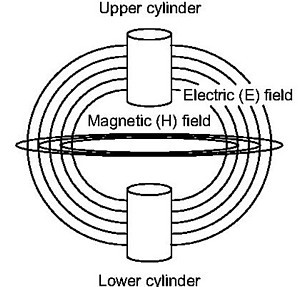
    try to include 3d electromagnetic theory when viewing the image


    as a comparison Felix Ehrenhaft: Magnetic Current


    Leave a comment:

Working...
X