Announcement

Collapse
No announcement yet.

Found treasure, could use some advice

Collapse
X
 
  • Filter
  • Time
  • Show
Clear All
new posts

  • #31
    Quick thought just flashed through my mind.
    Ignition coil, magneto, spinning wheel....
    Erm, if you made a flat surface to mount the gear on, then turned the wheel 90 degrees and put 3 more at the other corners, you have a car.
    Use the HV from a Slayer circuit wireless system to power the coils that then resonate with the transmission tower.
    Paint it all black and there ya go, pulse motor technology, Tesla wireless powered Model T

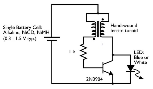
    For exciter tests - I recently re-posted the Mega-test PDF of common transistors in the Joule Thief exciter thread, so hopefully that helps. Anything I do comes from junker boards. Mainly though, for any transistor you put '2S' in front of the number, such as a C945 as seen written on it becomes 2SC945. Just type that in in Google and you'll get the datasheet. Look for high hFE (like 200+), low saturation voltages (like 0.3V) and a switching speed of above 150MHz. Power handling should be above 500mA for an all round winner and some kind of heatsink should be used for long period tests.
    PNP transistors are just as good to find as NPN's, but the Slayer circuit, as is, is for the more common NPN's.

    I've just broken a reed switch myself, one of the dark green glass ones. It just sits there stuck now. Thing is, it was running from about 1V off a solar panel, so i'm thinking its a combination of the neos being too strong and the switching speed being too quick.

    Comment


    • #32
      Ok, none of the switching methods I have tried have worked so far. the best coil I have to use is currently being fitted with a core, so I won't have it for a few days I think... (my father in law can get some iron stock that might fit the hole in the spool, so he took it with him to see what he could find)
      the other coils I have wound are small, and don't act like they are triggering the transistor I am messing with (2n3055), not really sure. nothing is happening anyway. I have some other transistors I can test, but I am going to try that later.
      all my reed switches are dead for sure, so that really limits my options. I pulled a 12VDC relay switch out of a computer monitor circuit board, and it would automatically switch on and off, but only very slow. maybe just under 1 second per pulse. great bright flashes out of the neon, but not enough current to make the plasma. what I need is a normally off switch that can be activated through a magnet, and not a coil. (I guess that would just be a reed switch )

      I am going to look into the slayer exciter circuits, and try the tesla coil driver that dR-Green posted.
      it might be a while before I have any useful updates, lots of reading to do.
      I have watched a ton of videos about exciter circuits, but I have no idea how they work, or even how to put one together. have to find a few diagrams, and it sounds like I need to wind up a tower.
      might try one of Sliders mini towers, but I really should look into what i need first.
      I have a distinct feeling that I am about to learn a whole other side of this quest for energy
      thanks for the ideas and suggestions! keep em coming. until I find a good triggering method that activates the primary coil, I am stalled.
      this is what I call adventure experimenting (just try stuff till something works, and figure out why later, and work really hard at not hurting myself in the process. sometimes inexperience can be a painful thing )

      N8

      Edit: Ok, I tried the tesla coil driver posted by dR-Green, and with the wall wart set @ 12V I got the same 3 second pulsing, and when I hooked it up to a 12V 7Ah battery, it melted the transistor I was using (TIP120, which was the closest thing I had to a TIP125, which was what I found to replace the transistor that the circuit called for... long story, but I used what I had handy) smoke coming out, and everything. I had even used a slightly bigger resistor into the transistor that the circuit called for, just for extra protection...

      that tells me something was shorted, and it's possible I killed the transistor with the wall wart, but that one pulses it's self, so it didn't get hot enough to melt anything.

      back to the drawing board. I think I am going transistor hunting in my circuit boards, see what I can find and identify that might work better.
      Last edited by Neight; 07-27-2011, 05:31 AM. Reason: added info
      The absence of proof is not proof of absence

      Comment


      • #33
        Alrighty, yes, a good idea can scare off unfamiliar folks..I completely agree. Every day we read posts and I know that there is a moment where the hand metaphorically zooms over the top of my head ! *click* next thread
        What needs to happen in some cases, is a clear overview, simple enough idea to spark the mind a bit.

        A Slayer type exciter works like this -
        The transistor is being used as a switch, to switch on and off the power to the Primary coil, the couple of wraps that normally sit outside the main tower.
        How does it know when to quit firing and switch to off ? by the main tower energising and passing a trigger of enough energy out of itself to the Base pin of the transistor.
        The field inside the big tower collapses down again and the transistor fires again. Round and round it goes, switching, turning off, switching , turning on, switching, turning off.
        That's all it is !
        On the Slayer, we normally put an LED between the ground connection and the Base of the transistor, fitted the wrong way around. That shows us when we have power, brighter as the primary is adjusted up and down the tower sides...basically as a power strength meter.
        So, as a summary, it's a circuit that uses the power generated in the big tower to switch on and off the transistor thousands of times a second. Nothing happens if there's no pulse like that.
        As you can see, that's pretty much like a pulse motor, of which you are familiar with

        I did think of a crude way of switching. You could mount the neos on 4 little metal trays (they would stick to the metal). The trays are all connected by a wire, which then runs to the spindle of the rotor. You'd wrap a large area of many strands around the spindle, such that it made contact but lightly. Now, you put a piece of wire where your reed switch was and each tray touches that wire as it passes. When the rotor spins a pulse is given with each time the spindle wire touches that wire. It'd run like an open cased reed switch really.
        You may drop lucky and find that the plasma flashes can come from the spindle to trays wire...which would mean you could mount that spindle wiring connection a little away from the spindle, for a frictionless connection
        Would look really neat too if it worked like that.

        The spindle transfer has been tried here some months back, when I used to spin little planes around a desktop mounted tower (made from a radio aerial).
        Here's a vid, demonstrating the power transfer like that, so you can perhaps better see what i'm on about:
        ‪Sub gram Storch IXb - USB desktop pole‬‏ - YouTube
        Last edited by Slider2732; 07-27-2011, 05:36 AM.

        Comment


        • #34
          Originally posted by Slider2732 View Post
          Alrighty, yes, a good idea can scare off unfamiliar folks..I completely agree. Every day we read posts and I know that there is a moment where the hand metaphorically zooms over the top of my head ! *click* next thread
          What needs to happen in some cases, is a clear overview, simple enough idea to spark the mind a bit.

          A Slayer type exciter works like this -
          The transistor is being used as a switch, to switch on and off the power to the Primary coil, the couple of wraps that normally sit outside the main tower.
          How does it know when to quit firing and switch to off ? by the main tower energising and passing a trigger of enough energy out of itself to the Base pin of the transistor.
          The field inside the big tower collapses down again and the transistor fires again. Round and round it goes, switching, turning off, switching , turning on, switching, turning off.
          That's all it is !
          On the Slayer, we normally put an LED between the ground connection and the Base of the transistor, fitted the wrong way around. That shows us when we have power, brighter as the primary is adjusted up and down the tower sides...basically as a power strength meter.
          So, as a summary, it's a circuit that uses the power generated in the big tower to switch on and off the transistor thousands of times a second. Nothing happens if there's no pulse like that.
          As you can see, that's pretty much like a pulse motor, of which you are familiar with

          I did think of a crude way of switching. You could mount the neos on 4 little metal trays (they would stick to the metal). The trays are all connected by a wire, which then runs to the spindle of the rotor. You'd wrap a large area of many strands around the spindle, such that it made contact but lightly. Now, you put a piece of wire where your reed switch was and each tray touches that wire as it passes. When the rotor spins a pulse is given with each time the spindle wire touches that wire. It'd run like an open cased reed switch really.
          You may drop lucky and find that the plasma flashes can come from the spindle to trays wire...which would mean you could mount that spindle wiring connection a little away from the spindle, for a frictionless connection
          Would look really neat too if it worked like that.

          The spindle transfer has been tried here some months back, when I used to spin little planes around a desktop mounted tower (made from a radio aerial).
          Here's a vid, demonstrating the power transfer like that, so you can perhaps better see what i'm on about:
          ‪Sub gram Storch IXb - USB desktop pole‬‏ - YouTube
          That loud whooshing noise you can hear is that metaphorical hand running over my head right now
          I can sort of picture what you are talking about, but honestly, I have no idea how it would work.
          your video of that little plane flying was pretty sweet though! I spent the weekend with a bunch of guys who play a flight simulation dogfighting game, and one guy brought a RC helicopter. reminded me of some of your posts about motors and RC planes
          what you describe sounds a bit like a DC brush motor, sort rudimentary style, or maybe a loose commutator, something like it anyway
          which should work great with enough RPM, though I don't know if my skills are up to the engineering task just yet

          would any kind of hall sensor/transistor work? I have two very small hall sensors from PC cooling fans. both of them are 4 pin halls, and all of the circuit diagrams I have seen on the forum use 3 pin, so I have no idea how to wire one up to try it....
          I do have a few n-channel mosfets, but again, lack of experience with them is keeping me from trying them out
          other than a hall, or just going to radio shack and cleaning out their reed switch drawer, I am at a loss for a good fast switching circuit. solid state would probably be best or at least the most stable, but I may not have the proper components to make one up.

          I do have one of those fuji disposable camera circuits that people use as joule thief circuits, but again, I am not sure how to use one, let alone make one pulse like what Lidmotor came up with.

          Like I said, I think I need to actually delve into some research on exciters and joule thief circuits, and finally just learn something besides pulse motors

          get out and explore a little, you know

          N8
          The absence of proof is not proof of absence

          Comment


          • #35
            sorry for constantly posting like this, but as I find new stuff, i am trying to get things posted, so I don't forget anything. you never know what small detail will trigger an idea in someone

            I have tried another 12V relay switch, and gotten some different results, sort of

            this thing sort of makes the circuit solid state, or at least no rotor or magnets involved.
            I have split my power supply up, part directly to the relay, and the other part wired in series with the primary coil. this relay will work @ 12V and 9V and nothing less.
            I did have it hooked up a little bit ago with a parallel cap across the relay, and it would sort of work down to 6V, but only on one leg, and I wasn't getting any plasma effects anymore. funny thing was, @ 6V it would work on one leg, and above that it would work on the other leg. once I got up to 12V it would start that auto pulsing again, but faster, 2-3 pps
            I wired a pot in series with the power supply to the relay and wound up getting the 12V setting to work consistently on both legs, but again no plasma.
            once I took out the cap however, it started working sort of like before, fast noisy switching, good light from both legs of the neon, and it will make plasma, but only barely. the contacts have to be very very close to each other to get anything this way.
            I am going to try and make a video showing both effects, mostly because it works, and it took me all day to get here, and someday I hope to watch the video I make and laugh at myself for being so simple
            either way, I am getting results again, and will take some measurements and report back

            N8
            The absence of proof is not proof of absence

            Comment


            • #36
              Keep at it Neight, It is confusing to learn, I know, I've been in the same situation you are in, still am I guess, I just know a little bit more than I did last year. Things will click for you sooner or later and stuff will start to behave how you tell it to behave most of the time.

              I was going to suggest the circuit that dr-Green postd but it seems you already burned that one up. No matter. I found when that happens to me if I study the ashes sometimes I can see what happened.

              I think the main thing is you need to use a trigger to turn on a transistor or something so that the main current through the coil is not sparking between mechanical contacts.

              I have never used a hall sensor so I can't comment on those. And it's near on impossible to drive an exciter with forced oscilations if it is a small coil the resonant frequency will be very high so a self oscillator like the JT circuit is necessary, I cannot get them to work very well though, it seems some people can do the self oscillators well like slider and some can't like me.

              I hope it turns out you are one who can. Because it is a lot of fun. In my experience IC oscillators are not easy to get working well above a couple of hundred Khz.

              Have you tried connecting an AC wall wart to the coil primary? My ignition coil sparks up if I connect AC to it. Some small wall warts can be AC but I think most are DC output.

              AC or pulsed DC will work, I think the condensers in those coils should be non polarised. I'm not sure if a modern ignition coil condenser is polarised or non-polarised but I removed mine and replaced it with a non polarised 1uF capacitor and holy billyo did that make a difference. The standard condenser was 0.22uF so four times the capacitance.

              Cheers
              Last edited by Farmhand; 07-27-2011, 07:36 AM.

              Comment


              • #37
                Originally posted by Farmhand View Post
                Keep at it Neight, It is confusing to learn, I know, I've been in the same situation you are in, still am I guess, I just know a little bit more than I did last year. Things will click for you sooner or later and stuff will start to behave how you tell it to behave most of the time.

                I was going to suggest the circuit that dr-Green postd but it seems you already burned that one up. No matter. I found when that happens to me if I study the ashes sometimes I can see what happened.

                I think the main thing is you need to use a trigger to turn on a transistor or something so that the main current through the coil is not sparking between mechanical contacts.

                I have never used a hall sensor so I can't comment on those. And it's near on impossible to drive an exciter with forced oscilations if it is a small coil the resonant frequency will be very high so a self oscillator like the JT circuit is necessary, I cannot get them to work very well though, it seems some people can do the self oscillators well like slider and some can't like me.

                I hope it turns out you are one who can. Because it is a lot of fun. In my experience IC oscillators are not easy to get working well above a couple of hundred Khz.

                Have you tried connecting an AC wall wart to the coil primary? My ignition coil sparks up if I connect AC to it. Some small wall warts can be AC but I think most are DC output.

                AC or pulsed DC will work, I think the condensers in those coils should be non polarised. I'm not sure if a modern ignition coil condenser is polarised or non-polarised but I removed mine and replaced it with a non polarised 1uF capacitor and holy billyo did that make a difference. The standard condenser was 0.22uF so four times the capacitance.

                Cheers
                Thanks Farmhand!
                I have not been discouraged yet, and the more I learn, the more excited I get!
                You are exactly right, what I need is a trigger capable of consistent and fast switching, without the mechanical contacts to get fused together (sans arc in this case )
                I am going to look into joule thief circuits and see what I can come up with. I have the small transformer from the fuji cameras, so that will help, I just need to find a JT switching circuit that I have the components to build
                I have not tried an AC wall wart, though the same thought had crossed my mind. I will have to look through my mass of abandoned power cords and see if any of them are AC.
                I actually do have a sweep generator and a wide range oscillator that look like they are from the 40's. I would love to try those but i honestly have no clue on how to use them. it's something my wife's grandpa gave me when I started all of this, and i just now got them both out because of this testing. I am going to look for manuals for them on the internet and see if either one or both of them can give me a good HF input to run this coil on, and maybe get some good consistent results this way. more reading to do for sure, but I am positive I will find a useful solution.

                I agree that the condenser in this coil box should be non-polarized. according to the drawing of this box from the article I posted, I don't see how it could be polarized, though I honestly don't know much about condensers either, besides they are early capacitors.

                I think the next day or two will be nearly all research and not much testing, if I can keep myself from playing (it's hard to do, this stuff is so much fun to test )

                I do have a video being processed by youtube right now. as soon as it's done, I will post the link of it. not much new in it though, besides the relay I have working now, and some scope shots of it working.
                biggest thing in the video is the amps being drawn using this relay as opposed to the reed switch.
                reed switch input amps were around 150mA while the relay switch is eating up 1.5A
                with the higher amp draw required to run the relay, this thing has lost it's efficiency. I also get much shorter plasma stream this way too.
                I would love a variable power supply to control input voltage and amps, but that is for another day (perhaps when I have found a sponsor for my work )

                anyway, I will post the link soon, and thanks for the ideas and encouragement! very much appreciated

                N8

                Edit: got that video up, here is the link

                thanks for watching, and enjoy!
                Last edited by Neight; 07-27-2011, 09:06 AM. Reason: added video link
                The absence of proof is not proof of absence

                Comment


                • #38
                  Cool video, the first few frame's had me laughing straight away. That neon sure is putting out some light and the slow pulsing at 12 volts is wild. Those old coils are neat that they still work too. Good stuff.

                  Cheers

                  Comment


                  • #39
                    Originally posted by Neight View Post
                    Edit: Ok, I tried the tesla coil driver posted by dR-Green, and with the wall wart set @ 12V I got the same 3 second pulsing, and when I hooked it up to a 12V 7Ah battery, it melted the transistor I was using
                    Oh, no no no It looks that like me you're going to have some trouble/transistor popping experience through using batteries. I'd stick with a (current limited) power supply. I've switched to a 500mA supply just to try and protect things. For even more protection I plan to use a high power resistor so I can't put more than about 350mA through the circuit because I've already destroyed a 2N2222 which is supposedly rated for 500mA [edit] Sorry, make that 600mA. So I think it makes sense to put protective bits and pieces in place relatively early.

                    I had my father take a look at the (simple SEC) schematic (he's an electronics engineer) and they are effectively short circuits. If the transistor doesn't start oscillating, then it has to deal with whatever current your power supply is capable of putting through it. If that's coming from a battery, then I think you can kiss it goodbye.

                    What does the scope show is happening when you get this 3 second pulsing?


                    Have you tried this circuit?


                    ‪Simple SEC‬‏ - YouTube

                    Connect the primary winding in series with the rest of the circuit, and connect the "negative" ends (the start of the winding) of the primary and secondary together, if they're not already connected. Attach an aluminium tray to the secondary "positive" HV output, and another aluminium tray to the transistor base. Put an LED between the emitter and base like Slider mentioned, with the anode connected to emitter. Start with lower voltages, NOT 7Ah batteries just yet and if nothing happens touch the trays with your hands, but don't let them touch each other directly.

                    If this fails to work completely, then maybe this circuit doesn't work with that particular coil. To find that out, or whether it's user error or something else etc, seeing as you have a disposable camera circuit you can test the small trigger transformer coil from it. I think the "mods" make it look more complicated than it actually is, not that I've really looked into the tutorials or whatever, but they seem to be based on modifying the existing circuit and leaving it all on the board. Personally I'd find it easier to take all the parts you need off and then build the circuit you want. For that, the simple SEC is easy and as I say I think you already have everything you need (the trigger transformer).

                    From where I stand I don't think it's necessary for you to start making a tower just yet. If the start of the windings of your ignition coils are fixed together then you're a bit more limited, but otherwise I should think that these coils can be used instead of the towers, certainly to start playing with in such circuits that use these 6kV trigger transformers, as long as your coils are suitable for the task*. After all, isn't the point of this thread these coils you found, not winding your own?

                    *I made a Tesla coil for another reason but tested it with the simple SEC not expecting anything, but it worked even better than the 6kV trigger transformer. I also have a 15kV transformer but that doesn't work. I don't know what determines whether it works or not, so I'd say just try it. Also it seems that pancake coils are something to look into, if you do want to make your own tower/coil
                    Last edited by dR-Green; 07-27-2011, 04:54 PM.
                    http://www.teslascientific.com/

                    "Knowledge is cosmic. It does not evolve or unfold in man. Man unfolds to an awareness of it. He gradually discovers it." - Walter Russell

                    "Once men died for Truth, but now Truth dies at the hands of men." - Manly P. Hall

                    Comment


                    • #40
                      Originally posted by Slider2732 View Post
                      I did think of a crude way of switching. You could mount the neos on 4 little metal trays (they would stick to the metal). The trays are all connected by a wire, which then runs to the spindle of the rotor. You'd wrap a large area of many strands around the spindle, such that it made contact but lightly. Now, you put a piece of wire where your reed switch was and each tray touches that wire as it passes. When the rotor spins a pulse is given with each time the spindle wire touches that wire. It'd run like an open cased reed switch really.
                      This makes me think of a simple rotary switch An SSG could be adapted to do this, and then have many contacts on the rotor to get a much higher switching speed. I suppose it's getting a bit complex then though. Cool video btw, I had to laugh at the "oops" moment

                      Anyway, I don't know what this will do for this purpose but it might be worth a try


                      @N8: You probably have all the components you need to make a basic JT - 1K pot, 2N3055, and a ferrite toroid which you can find in power supplies, CFLs, computer monitors and motherboards etc. In fact if you use a CFL then you can also use the transistors from it. The only two I've cracked open so far contained 2x MJE13002 and MJE13003 respectively. Not bad

                      http://www.teslascientific.com/

                      "Knowledge is cosmic. It does not evolve or unfold in man. Man unfolds to an awareness of it. He gradually discovers it." - Walter Russell

                      "Once men died for Truth, but now Truth dies at the hands of men." - Manly P. Hall

                      Comment


                      • #41
                        Things will click for you sooner or later and stuff will start to behave how you tell it to behave most of the time.
                        And then sometimes when it doesn't, you shout 'wahayyy eureka'

                        the more I learn, the more excited I get!
                        Yeah, you just have to find a way of switching that on and off in MHz

                        What an adventure we're sharing in

                        The Simple SEC of Jonny's is quite excellent (that was my first ever exciter circuit foray). He explains things excellently, as well as Lidmotor or Lasersaber and all of those blokes videos are well worth stepping through one by one, as you have time. Most of the time, the guys draw up the circuit diagrams and step through what each part does too.
                        Whereas, Nullpoints over at OU forum summarised my own videos well as something like "Holy cow look at this effect guys and sorry about the cat in the background"

                        The Resonant HHO circuit is highly similar to the Slayer exciter types.
                        If you look at that diagram, the L1 and L2 are your Ford box, with even the cap in there
                        Producing HHO with the Ford coils, for a car application would be cool.

                        Btw, feel free to throw up some transistor numbers that you find on circuit boards and i'll look at the datasheets from here, if it makes things easier. I could then point out perhaps what makes one better than the other from within own testings.

                        Comment


                        • #42
                          Ok, just a quick update. I am doing a lot of reading today, and very much appreciate the circuit diagrams from dR-Green and Slider! I have a few torroids I can wind joule thief style, and see what I can do with that!

                          I did run to radio shack today and cleaned out their reed switches. I also bought a few large rectifying diodes.
                          I am uploading a circuit diagram of what I tried today, just so you can see it for yourselves...
                          this thing has diodes everywhere I could think to fit them, and even has 2 diodes leaving the reed switch, just to try and protect it. none of it is working. all it seems to be doing is limiting the power getting to the neon. at lower voltages, only one leg is lighting. and at all voltages, I am still getting the reed switch to stick... it's not quite as bad, mostly intermittent, but it's still not working right.
                          I am going to take the rest of today and read up on more things, but I wanted to post this quick update.
                          I will hopefully have more a bit later when I have more time to post
                          Thanks again for the suggestions, and I will try everything at least once!

                          N8
                          Attached Files
                          The absence of proof is not proof of absence

                          Comment


                          • #43
                            THIS might help you out squire...I did a replication of Mariucivic's Magnet Kicker today.
                            Everything came off one old PC monitor. Nothing fancy, just 3 components and all easy enough to follow I hope.
                            Runs from 4.5V, and probably best at your 6V requirement (which is how I run it in the video).
                            It's been found to be chock full of weird features too. Like that the coils sing and buzz and that the rotor speed remains near enough constant, no matter what voltage is thrown at it. Current draw is unknown, but it's a solution, running from a similar wall adapter to the one you are using.
                            It works and it works very well.
                            After the video, the pickup coil was changed out to one of those tiny dozen or so wind chokes found on such circuit boards, the ones with the mini ferrite running through them....it works just as well
                            Save Radio Shack from inventory underload

                            ‪Magnet Kicker - replication‬‏ - YouTube

                            The pic below shows it running with the tiny ferrite choke as pickup coil and demonstrates that very little feedback of induced voltage is required to switch the MOSFET.

                            Last edited by Slider2732; 07-28-2011, 03:49 AM.

                            Comment


                            • #44
                              Would it be possible to use a standard 120 v float switch modified with a magnet attached? The type used on air conditioning air handlers.

                              Comment


                              • #45
                                Originally posted by Slider2732 View Post
                                THIS might help you out squire...I did a replication of Mariucivic's Magnet Kicker today.
                                Everything came off one old PC monitor. Nothing fancy, just 3 components and all easy enough to follow I hope.
                                Runs from 4.5V, and probably best at your 6V requirement (which is how I run it in the video).
                                It's been found to be chock full of weird features too. Like that the coils sing and buzz and that the rotor speed remains near enough constant, no matter what voltage is thrown at it. Current draw is unknown, but it's a solution, running from a similar wall adapter to the one you are using.
                                It works and it works very well.
                                After the video, the pickup coil was changed out to one of those tiny dozen or so wind chokes found on such circuit boards, the ones with the mini ferrite running through them....it works just as well
                                Save Radio Shack from inventory underload

                                ‪Magnet Kicker - replication‬‏ - YouTube

                                The pic below shows it running with the tiny ferrite choke as pickup coil and demonstrates that very little feedback of induced voltage is required to switch the MOSFET.

                                Hey slider!
                                nice video and replication of the magnet kicker!
                                I think I must not have been clear though
                                I can spin my rotor no problem, actually the rotor was only being used as a trigger for the reed switch to break the current to the primary of the ignition coil.
                                your video did give me an idea I would like to bounce off of you though.
                                do you think it would be possible to use something like the magnet kicker or the SG circuit, but instead use a trifiler coil? use two of the windings as a standard bifiler to run the motor, and use the third winding on the primary of the ignition coil as the trigger for turning it off and on?

                                I was also thinking of using an SSG circuit, and putting a big pot on it, like 5k or bigger, and turning the resistance up until the coil self oscillates. then instead of hooking it up to a battery on the output, wire it directly to the primary of the ignition coil.

                                I would prefer solid state switching to rotor driven, as I am having trouble finding a switching trigger that doesn't burn out

                                I might try the SSG set to self oscillate today, and see what that gives me.


                                @Iotayodi I don't know if that would work or not. I looked them up, and they are normally open, all that would be needed would be to find a way to get it to open and close @ HF to make this work! I will look into it further today, and thank you very much for the suggestion!
                                The absence of proof is not proof of absence

                                Comment

                                Working...
                                X