 Tweet
Tweet
Originally posted by Kokomoj0
View Post
is important to note, I am not inputting a sine wave to the transformer, I am
inputting a Square Wave. I wouldn't test for resonance using a sine wave input.
And because the primary is shorter but has .2 uf capacitance across it but
the secondary did not have added capacitance and I was pulsing the primary
at it's resonant frequency with it's added capacitance 530 khz, therefore the
secondary was free to oscillate with no added capacitance and it's resonant
frequency with no added capacitance is quite a bit higher than that, the
coupling is not tight and it's air cored. When I add 18 nF to the secondary the
secondary matches the primary frequency and the waveform gets bigger and pure sine wave.
Without the .2uF capacitance across the primary it's resonant frequency is
also in the Mhz. The primary coil inductance is 0.036 mH both combined and
the secondary coil inductance is 0.234 mH for the low voltage coils for
testing, and 61.6 mH for the high voltage coils I made.
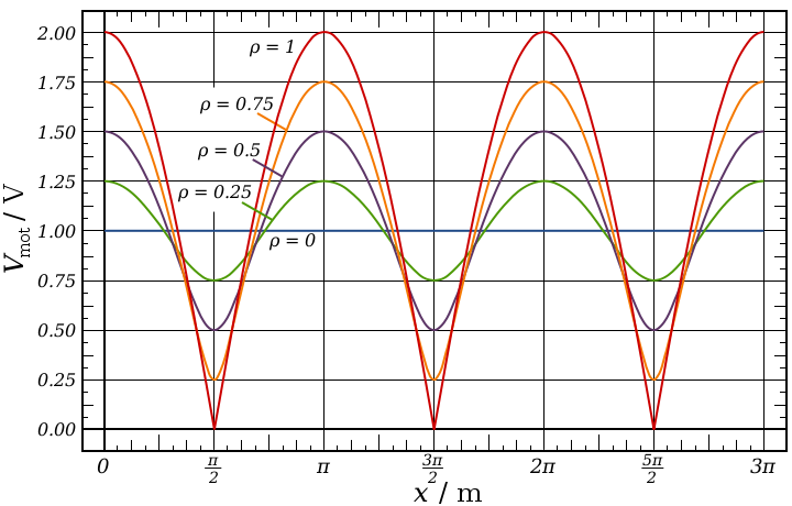
That can also happen the other way with the secondary in resonance and the
primary oscillating much faster, which is probably what is seen with most
Tesla coils, Not a nice clean sine wave, because the primary is not oscillating
at the same frequency as the secondary, for best results I think the primary
should be made to oscillate at the same frequency as the secondary to get a
wave form like this below.
Tesla states the waveform should be almost perfectly sinusoidal from a Magnifying Transmitter too I read.

Uploaded with ImageShack.us
I only showed it for curiosity sake it's nothing really useful. I just seen it on
the scope when I was messing about and took the snap to show it.
Cheers


 good fun.
 Nice work you can raise and lower the
") For some reason most/all bulbs I've tried produce plasma with one wire except the 15w ones
For some reason most/all bulbs I've tried produce plasma with one wire except the 15w ones 

 It's a bit small so I might have trouble in terms of capacitors and what not, but I'm getting some results so far. I have the TC output going into a tub of water, connected to a piece of metal, and an apple pie tin on the other side connecting to an AV plug going to where the battery used to be in the sub. So doing the tests on dry land before setting sail
 Are you using a neon across the fets at all? There's a lot of stuff to pay attention to with the HV, that's another reason why I think a simple NST setup would be better. Only the spark gap to adjust then. I broke a 2N3055 the other night when using two of them instead of the BUX81. I assume it was the spikes that did it because they looked pretty huge. With 2x 2N3055 (more gain than the BUX81) the neon wasn't just orange or pink, there were really bright white/purple flashes as if it was arcing inside, and I only saw that twice before the transistor was completely destroyed. So getting more power into the spark gap/TC is a real problem with this sort of setup I think.

 Click the image to be able to read it.


Comment