Announcement

Collapse
No announcement yet.

Tesla's Magnifying Transmitter "Replications"

Collapse
X
 
  • Filter
  • Time
  • Show
Clear All
new posts

  • Kokomoj0
    replied
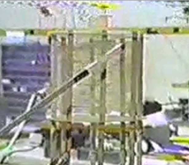
    from the vid, it looks like eric wound a distributed capacitance coil?


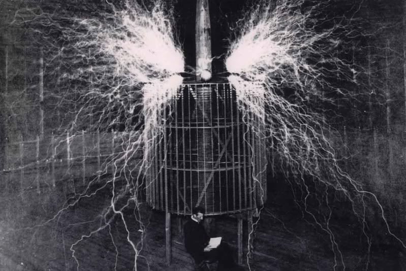
    here are a few of teslas design
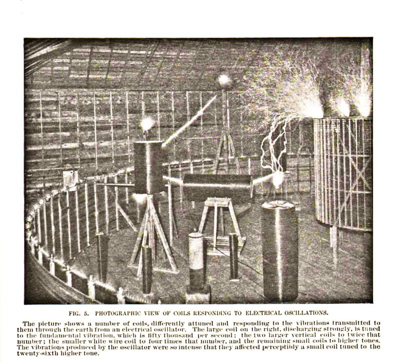


    it looks like its nearly log spacing toward the top?


    Here is more:

    I have gotten emails over the years and do not know where most of this stuff comes from, if there is a problem with posting it email me and I will be happy to remove whatever.....
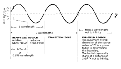
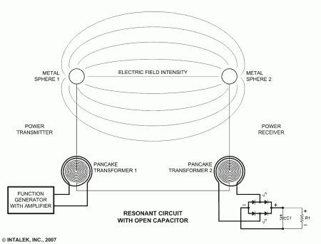
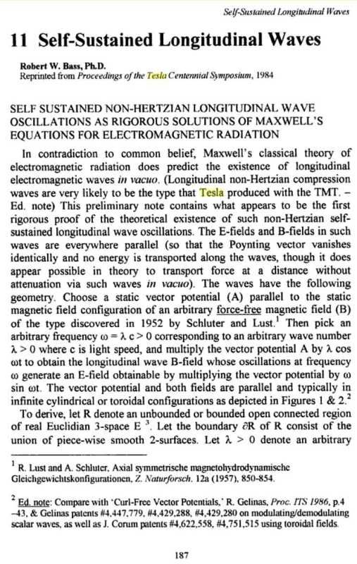
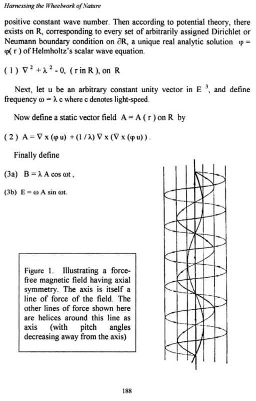
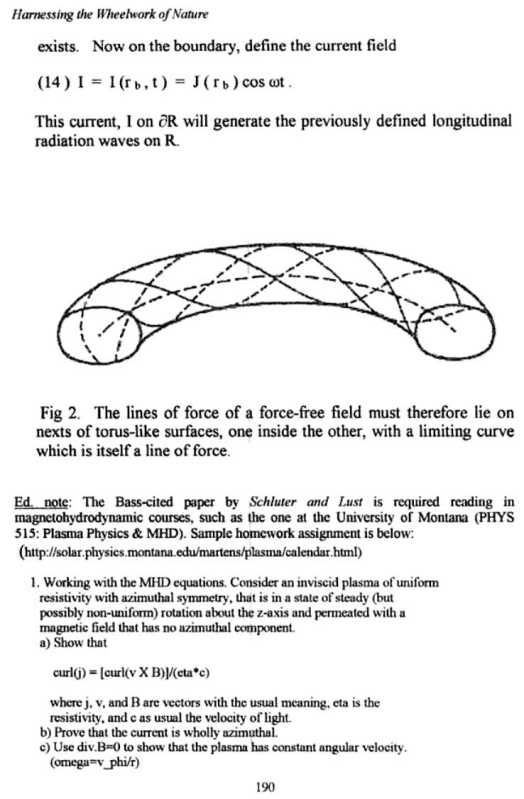


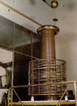
    another coil that looks like they used distributed capacitance which could be for insulation and or could also be required for proper design?
    Last edited by Kokomoj0; 11-13-2011, 05:27 PM.

    Leave a comment:


  • Kokomoj0
    replied
    Farm,

    You may find this interesting.

    Are you sure that your coils are operating at 1/4 wave?

    it seems to me that one of those articles you had from tesla said the transmitter as a system needed to be adjusted for 1/4 wave and of course if you want to get any kind of real power out of it, it wil also need to have a nice standing wave for both your transmitter and rec at the operating freq.

    Beyond matching them to be identical resonators mechanically then matching the impedance for a good transverse standing wave, then retune the freq like meyl to match the 1.2 - 1.57 speed I would think that is all the is necessary to get max output aside from raising the voltage and getting them up in the rarified air as tesla put it.


    I think you will find this interesting.


    Transverse & Longitudinal Electric Waves - Eric Dollard And Thomas Joseph Brown on Vimeo

    Tesla's Longitudinal Electricity - Eric Dollard, Peter Lindemann & Tom Brown on Vimeo

    Standing Waves Generated by String Vibration - YouTube

    Loop antenna resonance measurement with the MFJ-259B - YouTube

    Standing Wave Ratio explained - YouTube

    ECE3300 Lecture 12b-8 Smith Chart VSWR, lmin,lmax - YouTube

    ECE3300 Lecture 13b-1 Impedance Matching Intro - YouTube


    Homebrew antenna tuners - YouTube

    LL-Tuner by PA0LL.mpg - YouTube

    ECE3300 Lecture 6 4 Standing wave ratio - YouTube


    ECE3300 Lecture 30-1 Plane Wave Reflection and Transmission, Oblique Incidence - YouTube
    ECE3300 Lecture 30-3 Plane Wave Transmission and Reflection, Oblique Incidence - YouTube
    ECE 3300 Lecture 30-2 Plane Wave Reflection and Transmission, Oblique Incidence - YouTube


    Last edited by Kokomoj0; 11-13-2011, 07:40 AM.

    Leave a comment:


  • Farmhand
    replied
    No probs dR, simple miss understanding, but I think resonance is what it's all about with Tesla coils.

    Moving on. I mounted the one finished coil in the snake light board and
    scoped it, it looks good so far that's with 100 volts ATT on the scope no
    vertical gain and the probe is on 10X so it looks ok, I used only a very narrow
    pulse width so as to keep the voltage down and try to fit it on the screen.

    looks like 1000 volts peak to peak just pulsing the primary any old how, it'll be a
    lot more when I set it up properly and double with both. It's only 53 Khz for
    that shot.


    Uploaded with ImageShack.us

    Here is the test bed.


    Uploaded with ImageShack.us

    Cheers

    P.S. I can poke things in the center of the coil from the side, it's good fun.

    ,,
    Last edited by Farmhand; 11-13-2011, 06:05 AM.

    Leave a comment:


  • dR-Green
    replied
    Originally posted by Farmhand View Post
    Here's a video of the bodgey coil winding jig I didn't make. It just a
    video showing how I wound the secondaries with the wax paper and cordless drill.

    HV Coil winding 1.wmv - YouTube
    Looking good I'll go back and read the details after coming up with a spark gap magnet separator that doesn't involve a flammable piece of car tyre

    Leave a comment:


  • dR-Green
    replied
    Originally posted by Farmhand View Post
    So what parameters did you know you would have before you wound your coils ? Did you know the what the resonant frequency would be ?

    What exactly do you mean by "certain parameters" ?

    Cheers

    P.S. Have you checked to see if your primary is resonant at the same
    frequency as the secondary and that both transformers are the same ?
    None, it was an experiment, built totally blind. That's what I don't want to be doing, and that's why I want to know these things. By certain parameters I mainly mean lengths of secondary and primary (and the frequency), their weights, and by getting familiar with the differences between various combinations I hope to be able to figure out what combination might work best. To begin with I seem to be more concerned with the amount of copper (whether that be length, weight or both) rather than number of turns, in the secondary at least. For example first on the list will be like the example coil I said earlier, these aren't necessarily the exact figures, but 1 metre primary and 9 metre secondary. Then 1 metre primary, 7 metre secondary, and so on. The purpose of which is to ultimately be able to build a 1/4 wavelength coil of a certain naturally occurring event, or source or whatever.

    I haven't checked the resonance of these coils yet (after saying what I just said ), before I can do that now I'll be needing to glue up the receiver and assemble the function generator kit. The latest thing is that I'm fiddling with the 555 again and comparing things, which I think is good to know before thinking the coil is making any difference. And my spark gap actually burst into flames a few days ago when I was putting the power up and trying to get bigger discharges So I'm going to tweak that before I do any more I think...

    I'm just saying
    matching the weight will not necessarily automatically match the resonant
    frequencies of the primary and the secondary. Nor will making the primary
    1/4 the length of the secondary in my opinion.
    Well then, be it know for any future readers or newcomers that I don't think that will happen either and that's not what it's about

    Leave a comment:


  • Farmhand
    replied
    Originally posted by dR-Green View Post
    So you know in advance, or you're building it with certain parameters in mind, the same reason you measure the physical dimensions of the materials and know them before you begin. Practicality, though you don't really need to know any of these things to throw a coil together and get something out of it.

    But personally I want to know because I have plans that will be based on experimental data and certain values of things, so first I need to experiment and gather that data
    So what parameters did you know you would have before you wound your coils ? Did you know the what the resonant frequency would be ?

    What exactly do you mean by "certain parameters" ?

    Cheers

    P.S. Have you checked to see if your primary is resonant at the same
    frequency as the secondary and that both transformers are the same ?

    Leave a comment:


  • dR-Green
    replied
    Originally posted by Farmhand View Post
    Measure the wire for what though ?
    So you know in advance, or you're building it with certain parameters in mind, the same reason you measure the physical dimensions of the materials and know them before you begin. Practicality, though you don't really need to know any of these things to throw a coil together and get something out of it.

    But personally I want to know because I have plans that will be based on experimental data and certain values of things, so first I need to experiment and gather that data
    Last edited by dR-Green; 11-13-2011, 03:46 AM.

    Leave a comment:


  • Farmhand
    replied
    Here's a video of the bodgey coil winding jig I didn't make. It just a
    video showing how I wound the secondaries with the wax paper and cordless drill.

    HV Coil winding 1.wmv - YouTube

    I need to build an input voltage doubler circuit and a new PWM type board
    to handle the two primaries in parallel for this mirror transformer.
    I should be able to use it up to 400 or 500 Khz air or oil cored or somewhat
    less with a ferrite rod core ( I might be able to make that insertable )
    even with the oil in the housing because the center of the core can remain
    open right through. I'm going to stick with 12.5 layers at 1700 turns per side.
    I think for my purposes that will do the job, 44 turns primary and 1700 secondary
    should give me a conversion rate of 1 to 38.6 or much higher with resonance.

    With 30 volts input that should give me 2318 volts minimum between the two secondary
    HV terminals. I'll bolt all the wires to terminals outside the housing after
    bringing them out through grommets including the center tap so I can connect it to
    something if I want.

    I only need a good enough voltage to charge a primary tank capacitor run a spark gap
    at high frequency, like dR theorized in a previous post. Make the gap fire on the peaks.

    Back to winding the second secondary.

    Cheers

    Leave a comment:


  • Farmhand
    replied
    Originally posted by dR-Green View Post
    Yes maybe you're right about solid state. I don't see how it's not practical to match the weights though, personally I find that it makes it a bit easier, unless you're measuring the wire, in which case it would just be more work for more deliberate or focused results, or in other words maybe a lot more scientific because of the attention to details. If you're not measuring the wire then it's certainly a good alternative. Not doing any of these things and just winding whatever parts are at hand is just laziness
    Measure the wire for what though ? There is no need to measure the wire.
    Unless to measure the wire to determine the resonant frequency of the
    secondary in relation to the desired disturbance in the circuit (the frequency you want from it).

    It's not practical to have a primary 1/4 the length of the secondary either if a
    high turn ratio between primary and secondary is desired. ie if I want to use
    2000 volts and have a 1 to 1000 turn ratio so to get very high voltage then a
    single turn primary would be huge very thick and impractical if done by weight
    I could have I Kg of wire in the whole secondary (two coils).

    With spirals the weight might work out well because of the way the turns get
    progressively tighter. But still the weight alone will not determine the resonant
    frequency of the primary, that is determined by it's inductance and
    capacitance. Just because it weighs the same doesn't mean it will have the
    same resonant frequency or a multiple or fraction.

    I'm not saying it isn't a good idea if it works out as practical, I'm just saying
    matching the weight will not necessarily automatically match the resonant
    frequencies of the primary and the secondary. Nor will making the primary
    1/4 the length of the secondary in my opinion.

    Cheers

    Leave a comment:


  • dR-Green
    replied
    Originally posted by Farmhand View Post
    P.S. Eric talks of coils that are about 100 turns about equal in height to
    diameter and one primary turn, this may be OK for spark gap inputs, but it
    won't work so well for solid state. And that does not take into account the
    third coil.

    I'm only making comment on this because it was mentioned again here.

    It's not practical to make the primary the same weight as the secondary in
    most cases and not necessary and I am yet to see any real world evidence it
    is beneficial which would be very difficult to prove.


    ..
    Yes maybe you're right about solid state. I don't see how it's not practical to match the weights though, personally I find that it makes it a bit easier, unless you're measuring the wire, in which case it would just be more work for more deliberate or focused results, or in other words maybe a lot more scientific because of the attention to details. If you're not measuring the wire then it's certainly a good alternative. Not doing any of these things and just winding whatever parts are at hand is just laziness

    Leave a comment:


  • dR-Green
    replied
    Originally posted by MonsieurM View Post
    Have you thought that maybe the weight is related to the gauge of the wires...I would think the that the thicker the wire is , the heavier it is
    Yes, but I don't think that's an indication as to what gauge of wires to use, it just narrows the range depending on where you're starting from. There are a lot of different combinations you could use to get particular lengths and matched weights.

    Anyway I don't think it's necessary in order to get results, but I do think that it forms a deeper level of tuning.

    As for my spiral coils, being a complete experiment and having no idea how much wire I'd need or what gauge, it was the only indication - how much copper was in the primary. Make the secondary match it, and see how it turns out. I don't even know if they are tuned in any way whatsoever besides the weight, they just do what they do

    Leave a comment:


  • dR-Green
    replied
    Originally posted by Farmhand View Post
    Hi dR, The energy does travel up the resonator in a steep spiral and doesn't
    follow the helix of the coil, it see the resonator as a large diameter conductor
    not a helical coil. This is well known and I mentioned it in the Tesla Jackson
    thread long ago. And I am aware of the equal mass thing but that is not
    practical when we want a higher primary to secondary turn ratio and not really necessary.

    And on top of that the primary being equal weight to the secondary does not
    make it's resonant frequency the same or a fraction or multiple. The primary
    coil must be tuned with caps to do any of those unless you get very lucky.

    I realize you didn't say that dR but matching the weight doesn't give you
    automatically resonant coils. The tuning principals need to be still understood
    to get the best from the coils.

    So we see the primary being a quarter length of the secondary means very
    little. And matching the weight doesn't make them tuned resonant either.

    The transformer needs to be tuned, especially if pulsing not strictly at the
    resonant frequency with solid state methods.

    I can see all this on my scope. And test it with the function generator.

    Cheers
    I'm not saying that the weight has anything to do with making them resonant, at least not in the way we're talking about here. Then again if some physical object or material has a resonant frequency in itself, would that not remain constant regardless of its shape... You could make it into a box that resonates at a certain frequency, but the box still consists of the material. So two identical boxes of the same amount of material would be more closely tuned to each other in the physical realm than different amounts of material formed into the same shape cavity to resonate at the same frequency. They would in effect be tuned in an additional dimension than just shape, or length.

    If you want different turns ratios you can just use different thickness of wire to keep the weight constant.

    I just listened to the part of the video where Eric mentions the weight or volume matching before posting this, and with the skin effect he says it probably applies to equal effective surface area. "The simplest way to do it is by volume" IE plonk it on the scales and chop it when you have them matched With time and lot of wire it would be possible to figure out how much of what thickness you'd need for various lengths and weights etc.

    Leave a comment:


  • Farmhand
    replied
    Originally posted by MonsieurM View Post
    Have you thought that maybe the weight is related to the gauge of the wires...I would think the that the thicker the wire is , the heavier it is
    Yes of course thicker wire will be heavier for the same length.

    ..

    Leave a comment:


  • Farmhand
    replied
    Hi dR, The energy does travel up the resonator in a steep spiral and doesn't
    follow the helix of the coil, it see's the resonator as a large diameter conductor
    not a helical coil. This is well known and I mentioned it in the Tesla Jackson
    thread long ago. And I am aware of the equal mass thing but that is not
    practical when we want a higher primary to secondary turn ratio and not really necessary.

    And on top of that the primary being equal weight to the secondary does not
    make it's resonant frequency the same or a fraction or multiple. The primary
    coil must be tuned with caps to do any of those unless you get very lucky.

    I realize you didn't say that dR but matching the weight doesn't give you
    automatically resonant coils. The tuning principals need to be still understood
    to get the best from the coils.

    So we see the primary being a quarter length of the secondary means very
    little. And matching the weight doesn't make them tuned resonant either.

    The transformer needs to be tuned, especially if pulsing not strictly at the
    resonant frequency with solid state methods.

    I can see all this on my scope. And test it with the function generator.

    Cheers

    P.S. Eric talks of coils that are about 100 turns about equal in height to
    diameter and one primary turn, this may be OK for spark gap inputs, but it
    won't work so well for solid state. And that does not take into account the
    third coil.

    I'm only making comment on this because it was mentioned again here.

    It's not practical to make the primary the same weight as the secondary in
    most cases and not necessary and I am yet to see any real world evidence it
    is beneficial which would be very difficult to prove.


    ..
    Last edited by Farmhand; 11-13-2011, 01:22 AM.

    Leave a comment:


  • MonsieurM
    replied
    Have you thought that maybe the weight is related to the gauge of the wires...I would think the that the thicker the wire is , the heavier it is

    Leave a comment:

Working...
X