Announcement

Collapse
No announcement yet.

Tesla's Magnifying Transmitter "Replications"

Collapse
X
 
  • Filter
  • Time
  • Show
Clear All
new posts

  • dR-Green
    replied
    Hi Farmhand. I've been away nearly up in north Wales for a couple of days camping in the forest and watching the World Rally Championship, I ran out of time as usual before leaving so didn't get a chance to say. Now I'm back and still wiped out after 18 hours of sleep

    Originally posted by Farmhand View Post
    Ok I was wondering if someone could point me to a reference of Tesla weighing
    his coils ? Is the primary supposed to be the same weight or a quarter.

    Or if by length, if the secondary is 250 meters long and has a resonant
    frequency of 640 Khz then if I use a piece of wire 1/4 that length it would be
    62.5 meters long and if I wound that on the outside of the secondary it would
    give me about 400 turns for the primary and it's resonant frequency would be in
    the Mhz.
    I'm not aware of Tesla mentioning weight (or mass) matching anywhere except that Eric Dollard says it. If the skin effect of whatever energy applies over a piece of wire, then why would it follow the path of the wire in a helical coil? It can equally see the whole coil as one big mass of copper and go straight up it, as if the winding itself around a cylinder is just a very wide cable = big surface area.

    Maybe that's something else to take into consideration. But then where is the reference that the primary should be 1/4 wavelength of the secondary? What I've picked up regarding the 1/4 wavelength thing is in relation to a source of energy that you're tapping into, IE for the radiant energy patents. Like a basic radio works.

    So, my ideas of "1/4 wavelength tuning" goes something like 1/4 wavelength secondary of whatever natural frequency that you intend to work with, NOT in relation to any other piece of wire in any coil in the whole setup.

    For example like a basic radio, you'd make a full wave transmitter, and have a quarter wave receiver. Don't ask me how the primary would apply to all of this because I haven't thought that far ahead But if the receiver "secondary" is 1/4 wavelength then it will be smaller than having the size of a radio transmitter in your house, and the part with greatest potential will fit between both ends of the wire and allow you to receive nicely.

    So if you want to tap the energy of lightning, then use quarter wavelength secondary of the frequency of lightning is how I would go about it.

    It was the odd number multiple that caught my attention. So my example coil would be 1 metre primary, 9 metre secondary, and just because Eric Dollard says it and for reasons that make sense in my head, try to use wires that are are somewhat equal in weight/mass at these lengths.

    So then if you make the secondary 1/4 wave of a natural source, the primary an odd division in length of wire and set the whole thing into motion, then the natural harmonic would coincide with the top of the coil where the peak of the wave will be. Don't ask me what effect an odd division length of primary would have, maybe to try and get both wires more closely matched with all the circuitry and terminals etc?

    Though I don't know which patent the odd multiple came from still. If it's not the spiral coils patent, then it's the MT I believe.

    The only 1/4 wavelength thing that makes sense to me is that the secondary needs to be 1/4 wavelength to have maximum potential at the top, of whatever energy that's coming into it. IE the "free energy" stuff through allowing the oscillation to grow via being tuned to a natural source from the environment.

    I challenge anyone to cut two pieces of wire one being 1/4 the length or
    weight of the other then wind them into a Tesla air cored transformer and
    show me resonance of both the primary and secondary without adjustment
    I won't be doing that (yet at least) because I I haven't been on about 1/4 length, but I will make a few coils based around odd numbers, and in time also bringing weight into it

    Leave a comment:


  • Farmhand
    replied
    Ok I was wondering if someone could point me to a reference of Tesla weighing
    his coils ? Is the primary supposed to be the same weight or a quarter.

    Or if by length, if the secondary is 250 meters long and has a resonant
    frequency of 640 Khz then if I use a piece of wire 1/4 that length it would be
    62.5 meters long and if I wound that on the outside of the secondary it would
    give me about 400 turns for the primary and it's resonant frequency would be in
    the Mhz.

    Here's a diagram showing the voltage gradients on the coil for the different
    frequencies.


    Uploaded with ImageShack.us

    I don't get it, I tune my coils to be resonant so that the secondary shows a
    sine wave and the maximum potential is automatically at the terminal.

    Full wave resonance would show a minimum at the center and both ends and
    two maximums between them.

    Half wave resonance would show a minimum at both ends and one maximum
    between them.

    And quarter wave resonance would show a minimum at the bottom and the
    maximum at the top which is what we want.

    Granted, the oscillations of the primary are indeed setting the frequency for
    the quarter wave resonance. But there is no guarantee that a primary 1/4 the
    length of the secondary will oscillate at 4 times the frequency of the resonant
    frequency of the secondary. It must be made to be like that. Which can be
    done different ways.

    I challenge anyone to cut two pieces of wire one being 1/4 the length or
    weight of the other then wind them into a Tesla air cored transformer and
    show me resonance of both the primary and secondary without adjustment.

    If a given secondary is 1/4 wave resonant at say 640 Khz then the primary
    can be resonant the same at the same frequency and in fact is better like
    that.

    Are you guys saying the primary for the secondary resonant at 640 Khz should
    be resonant at 4 x 640 Khz = 2560 Khz itself ?

    If not what exactly is it you are saying ? What is the intended result of the
    weighing of the coils or as some have suggested making the primary 1/4 the
    length of the secondary ? In technical terms.

    Cheers

    Leave a comment:


  • Farmhand
    replied
    Here it is so far. The Secondary measures 61.6 mH and 22.8 ohms. And so far
    is 12.5 layers with 136 turns per layer, so about 1700 turns, with home made
    bees wax paper between each layer. The resonant frequency with 1 pF works
    out by the calculator to be just right at 640 Khz.

    The primary is about 0.1 ohms and 0.018 mH. It's 20 turns of 10 amp auto
    wire so far, the way it is built the primaries can be changed.

    I think I'll try it like this, I just need to wind the other secondary.

    Good question Kokomo, This way the primaries are near the lower voltage
    windings of the secondary, the higher voltage is towards the outer diameter
    of the coil and the HV is taken off at the ends in my design away from the
    primary leads. The two inner ends of the secondaries near the primary leads
    are 0 volts or about. This way it could be used with HV input too.

    This is how i'll mount it in the PVC pipe.


    Uploaded with ImageShack.us

    One secondary with 1700 turns


    Uploaded with ImageShack.us

    Next to the drawing for reference.


    Uploaded with ImageShack.us

    Cheers

    Leave a comment:


  • Kokomoj0
    replied
    Originally posted by Farmhand View Post
    Hi all, I've been thinking about HV transformers.

    I think I might construct a transformer like this. I'm not sure what wire exactly
    I'll use yet, I've got a few different kinds. I can mount all the formers on the
    smaller PVC pipe and use a ferrite core if I want or use the stick. I an use a
    spacer between the two sets of formers as well.


    Uploaded with ImageShack.us

    I'll be able to put the whole setup inside a larger PVC Tube with screw on
    ends and bring the wires out through sealed grommets. Then I can fill it with
    transformer oil. I've got 40 liters of it but it needs boiling out.


    Uploaded with ImageShack.us

    I figure i can get about 5600 turns of 0.5mm wire on the larger outer formers
    which will be the HV secondaries.

    And I think I'll use two strands of 1mm wire wound next to each other in
    parallel for two layers of 30 turns each on the inner formers. This way I can
    use both strands on each primary in parallel and both primaries in parallel.

    That should give me with 24 volts input about 2200 volts between each
    outside and center or 4400 volts between the two outsides, but if it's in oil
    I should be able to use more on it.

    EDIT: Correction I should be able to get 4600 turns of 0.5 mm wire in the
    secondaries so that's about 1850 volts per side with 24 volts input. I wonder
    what frequency I'll be able to use on them. Any hints.
    I'm hoping to able to pulse them at 115 Khz at least, hopefully 230 Khz or more.

    If I can get 3600 volts at 230 Kz I'll be very happy.

    I should be able to get it all into a tube 90mm diameter and 250mm long.

    This is what I want to build for charging the primary capacitors on my HV air cored resonant transformers .


    why wouldnt you put the secondary in the center and primar on the outside?

    Leave a comment:


  • MonsieurM
    replied
    No Offense Taken Farmhand, you contributed much to my knowledge, just thought it might help in your experimentation...cheers

    and looking forward to learn from your input

    good luck

    Leave a comment:


  • Kokomoj0
    replied
    Originally posted by Farmhand View Post
    Looks like he is using about 300 watts input from the wall. Not sure of the
    output it could be as low as 30 watts or even less. It's not really clear what
    he's doing there, there is no way of telling if the desk lamp is also powered by
    the Tesla coil output or if it is powered by the supply transformer. Looks like
    the coils are very close and one is laying down for some reason. I can't tell how the setup is configured.

    The big question is how long can it be left running, he seems quick to turn it off.
    Probably because of heating mosfets. To be any use a setup needs to be able
    to run 24/7 not just in short bursts. Any pair of Tesla coils can do wireless
    transmission, it's just a matter of building them to be able to run continuously
    and with a usable output.

    Not much use if it's running lights and it can only be turned on for 10 minutes.

    I prefer if people when making a technical video explained a bit of what they
    are doing, he has some info in the video but not enough to satisfy my
    curiosity.

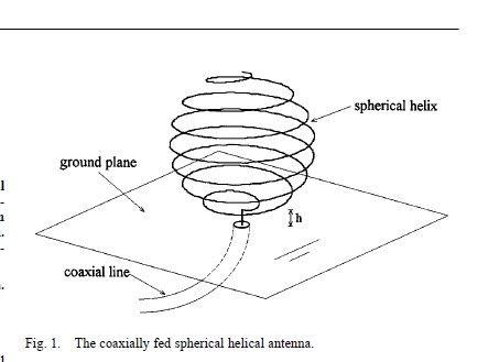
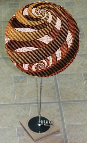
    Oh yeah I haven't got around to experimenting with the spherical antenna yet.

    Cheers

    most of those tests are simply near field rf or magnetic induction. tesla said in the court case his device was neither. In order to get proper test results it seems to me that a person has to get a minimum of 1.25 wavelengths away from the transmitter and ideally transmit through the ground which is where they should get the 292fps speed.

    Leave a comment:


  • Farmhand
    replied
    Hi MonsieurM, Please don't take this the wrong way, but I'm too busy.

    If it's plugged into the wall I'm not really interested, sorry. I am busy
    experimenting with my own direction so I won't be browsing any channels.

    I refuse take any notice of what people say who profess to have some fantastic
    device but do not show it.

    If I want to light 240 bulbs at less than unity from two feet I just use an
    inverter and a battery. I'm not chasing free energy, I'm experimenting and
    researching.

    I don't see what I'm supposed to get from the video. He had the plate only
    inches from the Tesla coil. If he was transmitting over 50 meters through a
    single wire or the ground and powering the setup from a battery I would be
    interested. As far as I can tell he is using power from the wall I power my
    experiments from the sun. I power my lights from the sun too mainly.

    Cheers

    Leave a comment:


  • MonsieurM
    replied
    one last vid from the same experimenter:

    Tesla Coil Negative "Pseudo" Electrostatic Output - YouTube

    Demonstration of how a tuned Tesla Coil emits rapidly varying impulses akin to electrostatic generators. While electrostatic generators simply build up a constant static charge, a Tesla Coil at it's 1/4 Wave peak output builds up an average one sign charge even if it is rapidly varying, respect to the ambient ground.
    This simple yet misunderstood concept distinguishes the Tesla Coil air core high tension transformer from any other standard "lumped" transformer theory.
    The thin aluminum leaf placed on the top load is charged with the same sign charge as the top, hence it is repelled as soon as, or near, resonance.
    The term "pseudo electrostatic" means that the output of the coil is not a mere "static" (constant) output, but rather oscillates at the resonant frequency of the coil and is characterized by a biased potential respect to ground.
    The reason for this effect is connected to the coil's self capacitance and self inductance which must be considered individually between every adjacent turn of the coil and globally, considering the high frequency operation. We can say that every turn of the coil behaves as an individual small LC circuit connected in series with the next, but also coupled due to proximity

    Leave a comment:


  • MonsieurM
    replied
    I found the vid while browsing a channel that was recommended by Z

    Originally posted by zilano
    folks!


    kdkinen's Channel - YouTube

    watch all videos and learn hv hf and resonance

    courtesy: mr clean!

    rgdz
    zzzz

    in the comment it was written:

    Experiment 4
    Inserted a metallic plate between two Tesla Coils - the receiving Tesla coil is still powering a 220V 60W lamp much over voltaged. Plate is connected to a 220V 40W lamp. Other side of lamp is connected to a 5 meter long wire just laying on the floor unconnected.
    The length of the wire determines the brightness as the wire has capacitance and inductance and it acts as a "choke" for the rapidly varying field potential in order to create a high enough current in the filament to light it. Connecting it to ground reveals the potential present by the arcing and brightens the lamp though diminishes the brightness of the lamp connected to the second coil as the field effect is reduced
    here is the channel of the experimenter:

    IceCoolDaIceMan's Channel - YouTube

    if you browse his uploaded vids, you'll find the ones with the Tesla experiment


    from his channel, interesting vid:

    Kapanadze - Tesla - Linde - YouTube
    Last edited by MonsieurM; 11-12-2011, 10:53 AM.

    Leave a comment:


  • Farmhand
    replied
    Originally posted by MonsieurM View Post
    Farmhand, i don't know if you have seen this vid before, but i think it might interest you

    Tesla Wireless Power Transmission - Experiment 4 - YouTube
    Looks like he is using about 300 watts input from the wall. Not sure of the
    output it could be as low as 30 watts or even less. It's not really clear what
    he's doing there, there is no way of telling if the desk lamp is also powered by
    the Tesla coil output or if it is powered by the supply transformer. Looks like
    the coils are very close and one is laying down for some reason. I can't tell how the setup is configured.

    The big question is how long can it be left running, he seems quick to turn it off.
    Probably because of heating mosfets. To be any use a setup needs to be able
    to run 24/7 not just in short bursts. Any pair of Tesla coils can do wireless
    transmission, it's just a matter of building them to be able to run continuously
    and with a usable output.

    Not much use if it's running lights and it can only be turned on for 10 minutes.

    I prefer if people when making a technical video explained a bit of what they
    are doing, he has some info in the video but not enough to satisfy my
    curiosity.

    Oh yeah I haven't got around to experimenting with the spherical antenna yet.

    Cheers

    Leave a comment:


  • MonsieurM
    replied
    Farmhand, i don't know if you have seen this vid before, but i think it might interest you

    Tesla Wireless Power Transmission - Experiment 4 - YouTube

    Leave a comment:


  • Farmhand
    replied
    Well well, if I space the primary and make it only two layers it ends up looking like a double barbers pole. Looks familiar.

    The primary will be much closer to the secondary in reality, I just drew it with a big gap.


    Uploaded with ImageShack.us

    Two of these joined should work well.

    Leave a comment:


  • Farmhand
    replied
    Hi all, I've been thinking about HV transformers.

    I think I might construct a transformer like this. I'm not sure what wire exactly
    I'll use yet, I've got a few different kinds. I can mount all the formers on the
    smaller PVC pipe and use a ferrite core if I want or use the stick. I an use a
    spacer between the two sets of formers as well.


    Uploaded with ImageShack.us

    I'll be able to put the whole setup inside a larger PVC Tube with screw on
    ends and bring the wires out through sealed grommets. Then I can fill it with
    transformer oil. I've got 40 liters of it but it needs boiling out.


    Uploaded with ImageShack.us

    I figure i can get about 5600 turns of 0.5mm wire on the larger outer formers
    which will be the HV secondaries.

    And I think I'll use two strands of 1mm wire wound next to each other in
    parallel for two layers of 30 turns each on the inner formers. This way I can
    use both strands on each primary in parallel and both primaries in parallel.

    That should give me with 24 volts input about 2200 volts between each
    outside and center or 4400 volts between the two outsides, but if it's in oil
    I should be able to use more on it.

    EDIT: Correction I should be able to get 4600 turns of 0.5 mm wire in the
    secondaries so that's about 1850 volts per side with 24 volts input. I wonder
    what frequency I'll be able to use on them. Any hints.
    I'm hoping to able to pulse them at 115 Khz at least, hopefully 230 Khz or more.

    If I can get 3600 volts at 230 Kz I'll be very happy.

    I should be able to get it all into a tube 90mm diameter and 250mm long.

    This is what I want to build for charging the primary capacitors on my HV air cored resonant transformers .

    Last edited by Farmhand; 11-11-2011, 01:37 PM.

    Leave a comment:


  • MonsieurM
    replied
    Farmhand, i was wondering if had the opportunity to experiment with


    Leave a comment:


  • Farmhand
    replied
    Here's some video from where I ran a small motor from the rectified output of
    the receiver, I only pulsed the transmitter at half the resonant frequency for this
    experiment, I did it like that just to see the available power plus I don't want to
    burn out the little motor.

    Small motor experiment - YouTube

    Cheers

    Leave a comment:

Working...
X