
@penno64 Interesting video.. I understand the diagram... and I think I understand what is happening... what is the amp draw? Thanks
@xee2vids, ok will do. I figure I will take a toroid, wind 100 turns, figure out the Al, then rewind for correct uH, if I can't find one that fits the bill. Been vusy building this.
Cheers
-
Leave a comment:
-
is this oneOriginally posted by penno64 View Post
for now work only with this bulb ,with 5watt bulb no successLeave a comment:
-
Hi Kyle,
Why don't you spend 5 minutes watching this one -
Joule Thief- Joule Ringer
Take special note of the two identical bulbs. One is in series from the supply.
Penno
p.s. circuit is posted at OU in joule thief thread, I think.Leave a comment:
-
Royer Resonant Drivers
@Xee2vids
I tried your mod, but couldn't get it to fire up.
My next trial circuit will be this one:
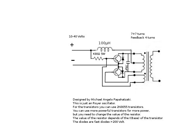
I'll probably drive it with mosfets instead, though.
Another really interesting setup, more high tech, and low voltage is outlined here:
Leave a comment:
-
SkyWatcher's split positive.
I spent a few days sketching up circuit schematics to switch the 3 batteries around automaticly in SkyWatcher's split positive Joule Thief system, when I hit on a pretty simple solution: 36 wires; Six SPST on off electronic switches, and a timer chip. Six wires from each of the battery poles to a long breadboard. Each set of wires arranged and connected in the next battery permutation order. The timer simply turns the switch on to each set of the 6 differently ordered wires sequentialy at 8 hour intervals, and Viola! A tiny photo voltaic cell should recieve enough power from the Super Joule Thief bulbs to recharge the 9 volt switch battery.Last edited by Allen Burgess; 03-20-2012, 05:11 PM.Leave a comment:
-
@xee2vids
Thanks. I tend to believe you on the short to ground, because when things DO go wrong, with my circuit, for example you decide to change capacitance and overdo it, or try a new FET... and if things go wrong, the ammeter hammers into the multiple amps, FET fries, 555 cooks. It's all or nothing LOL I have a little IC/FET burial ground from this experiment. Thanks I'll try what you have there, interestingly simple, like most of your stuff, it's been a lot of fun.Leave a comment:
-
@xee2vids
Thanks. I'm assuming you have over simplified the 555 setup, and meant the diagram to be a mod to what I already have set up as an oscillator?Leave a comment:
-
@ kcarring
Try this.
EDIT: If I understand what you are doing, when the capacitor is discharged the mosfet is shorting the power supply to ground and this energy is not doing anything (just wasted). With this circuit the energy goes through transformer and builds up magnetic field. I think this will give more brightness for the same current. However, I do think your circuit will give AC whereas this one does not (but it sort of does).
 Last edited by xee2; 03-19-2012, 07:57 PM.
Leave a comment:
-
Tony Van Roon 555 Oscillator Inverter Variant
@Xee2vids
Remember that 555 circuit we played around with? I got into it again tonight, this time using a 6V transformer, trying to reduce it to a single transistor, which never really worked, but I was able to get a FET driving it, and when I did, I got a wicked shock, and said.. hey! That's pretty good volts, damn.. so I hooked up a small CFL and seems like this circuit is rather "spikey" indeed. If not ultra-efficient, at least useful.. the light is ample for RV, evening, it's AC of course so should run out on wire nice, and it's dead quiet, no heat. Also, it's draw(1 watt or thereabouts) is identical to the output of these style solar panels that I get on sale for $9.99. Best of all, it's made from garbage you find, typically. No CT transformer needed, like the original circuit. I'm sure someone has done this, somewhere... so I won't take credit, but nonetheless it's a good little runner. I kind of like CFL driven at low levels, it's very easy on the eyes in a small space, like a camper / cabin.. LEDs tend to knock your brain sideways.
Cheers
12 Volt 1 or 2 Watt CFL Driver - 555 Oscillator / Inverter - Sentex Kyle Mod II - YouTube
*note: If you're not happy with the light, take a second 103 cap, and place it in series with the one on pin 2, to ground, this will increase the lamp to a 130 mA draw, still quiet and about doubles the output. (Still uploading)
This circuit is a modification of Tony Van Roon's 555 Oscillator Inverter. Tony has passed away unfortunately. It would be a good time to collect some of Tony's great work, who knows how long the site will remain online. R.I.P. Tony van Roon.
DC to AC Inverter With the 555Leave a comment:
-
That's correct with small joule ringer but not with super jouleringer..Originally posted by Allen Burgess View Post
Anyway, there are many methods how take energy out, but first the resonant circuit should start act as pump for external neutral charges... That's the main idea.Leave a comment:
-
Current transformer.
T-1000,
The output from a current transformer would be so small as to be almost entirely negligable; Merely enough to move the indicator needle on an amp meter at most, way down in the nano-amp range.Last edited by Allen Burgess; 03-16-2012, 04:16 PM.Leave a comment:


Leave a comment: