This forum is preserved as a permanent archive. The community continues at eMedia Press.

Announcement

Collapse
No announcement yet.

Stingo Solid State Battery Charger

Collapse
X
 
  • Filter
  • Time
  • Show
Clear All
new posts

  • #61
    Hi guys,

    I have spent the last couple of nights trying to get this simple circuit to osciliate.

    I have tried countless coils, transformers from PC psu, pinball machine coils all to no avail

    For my transistor pair, I am using TIP 31 and 32.

    10k pot and 100 ohm.

    I have also tried 7mix 100k to ground circuit.

    Any tips, greatly appreciated.

    Kind Regards, Penno

    Comment


    • #62
      I have found car ignition coils to be the easiest to oscillate. The bigger the coil, the lower the resonant frequency. Since most transformers are iron core this lowers the frequency even more.

      Also, as I mentioned once in passing, sometimes disconnecting and reconnecting the circuit with the pot set in the right position will kick it into gear. The initial transient probably gives it the kick it needs to open the first transistor and start the oscillation. Try adjusting the pot a little and then opening and closing the circuit, and repeat.

      Try different size batteries... try 6 volt and 12 volt.

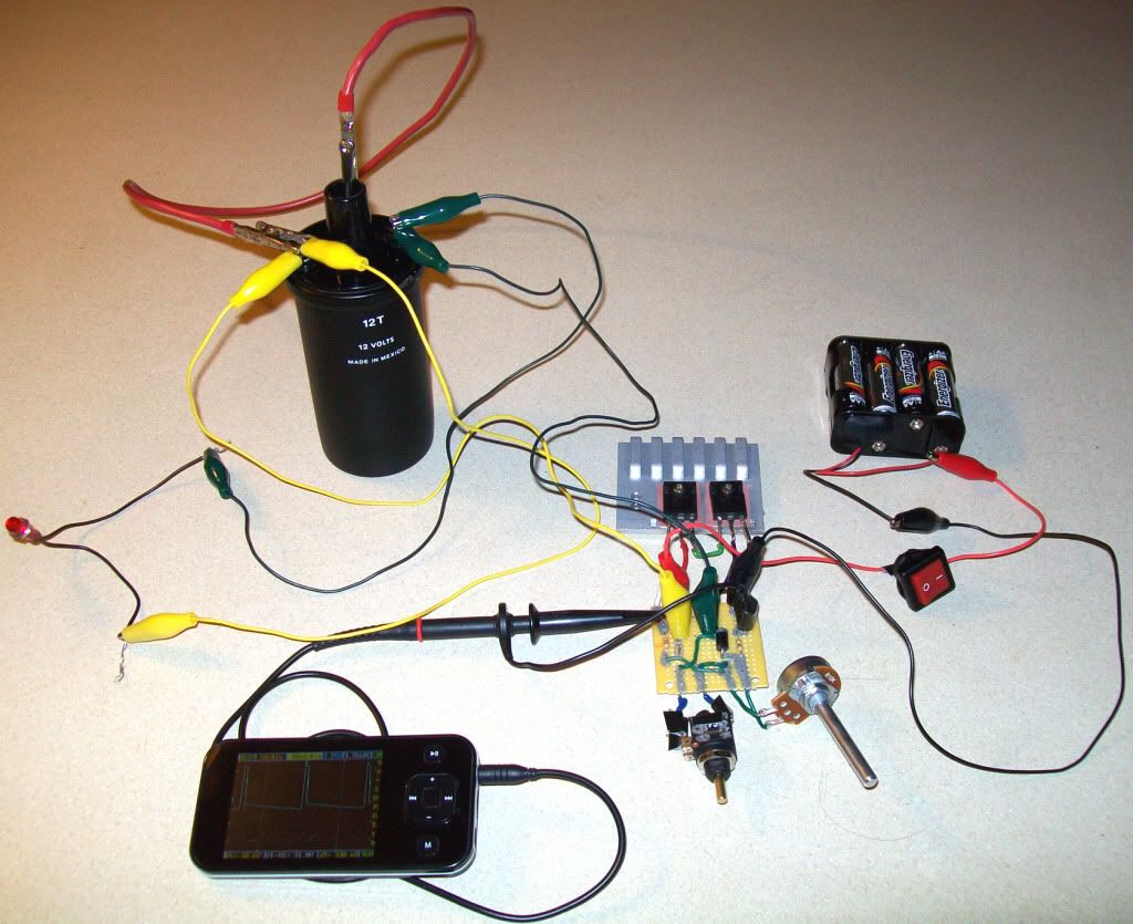
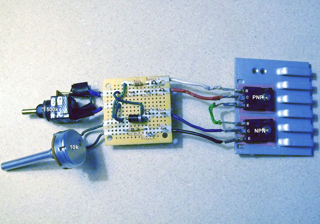
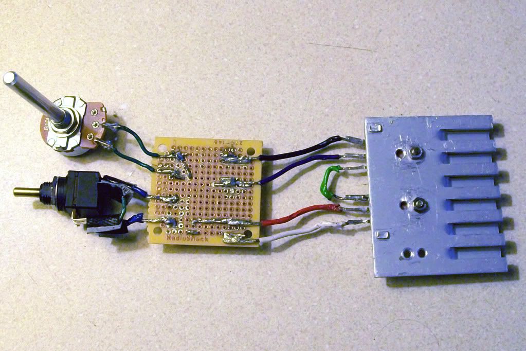
      Also, perhaps your circuit has a short or is connected improperly... Can you take pictures of your build and upload them so we can check for accuracy?

      Thanks for trying stingo, it's fun :-)

      Comment


      • #63
        Originally posted by penno64 View Post
        For my transistor pair, I am using TIP 31 and 32.
        Thanks for the interest . You do this?

        Comment


        • #64
          Thanks guys for the replies.

          I persisted and tried the HDD motor.

          What a buzz.

          Runs as low as 3.0v and screams at 12v.

          I will load up a you tube shortly.

          I configured this as the charger as well , and though I am seeing the spikes
          on the CRO, I could not get battery to charge any ?

          Once again, thanks sucahyo and 7mix.

          Regards, Penno

          Sorry guys, it is charging. I was biting off more than I could chew. I was trying to charge a 12v.
          On a 1.2 Ni-Mh, charges and rather quickly too.

          Thanks
          Last edited by penno64; 10-22-2010, 11:47 AM. Reason: New observation.

          Comment


          • #65
            irrelevant post coming.....


            Why did you choose to call your circuit's "stingo"?

            Comment


            • #66
              @Armagdn03:

              Originally posted by sucahyo View Post
              That is the origin of the name stingo . I sting my hand and found this weird circuit....

              Comment


              • #67
                Originally posted by penno64 View Post
                Thanks guys for the replies.

                I persisted and tried the HDD motor.

                What a buzz.

                Runs as low as 3.0v and screams at 12v.
                That is awesome. Looking forward to your videos.

                I haven't been able to drive a hdd stepper motor yet, but I did get it to oscillate once at a very high frequency. I need to solder some better leads onto my hdd motor so that testing is easier.

                Comment


                • #68
                  Originally posted by 7imix View Post
                  @Armagdn03:


                  ha ha ha, very nice!

                  Comment


                  • #69


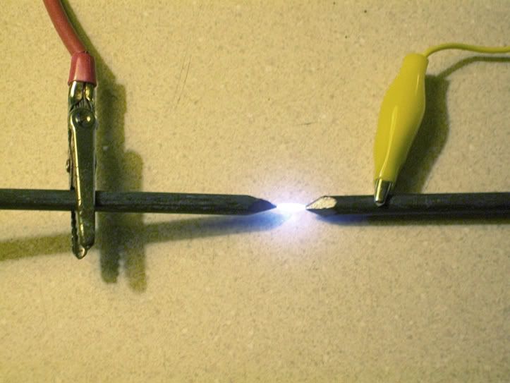
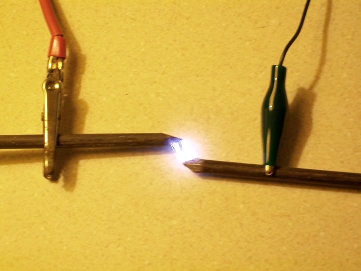
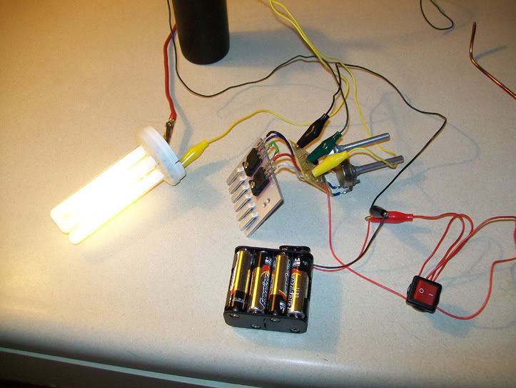
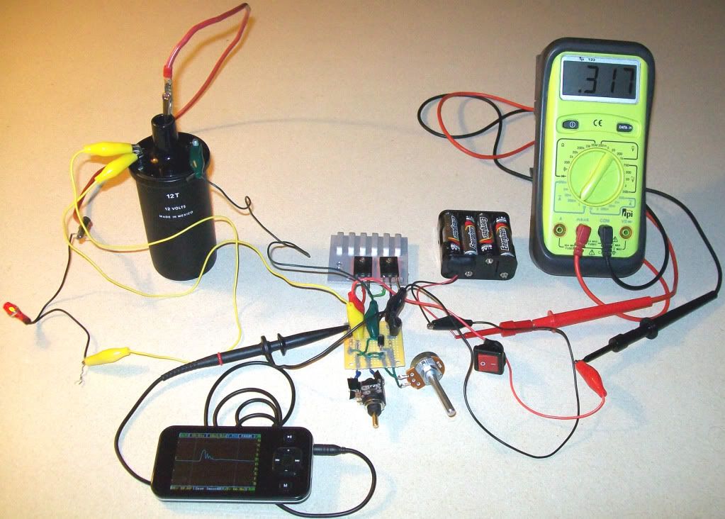
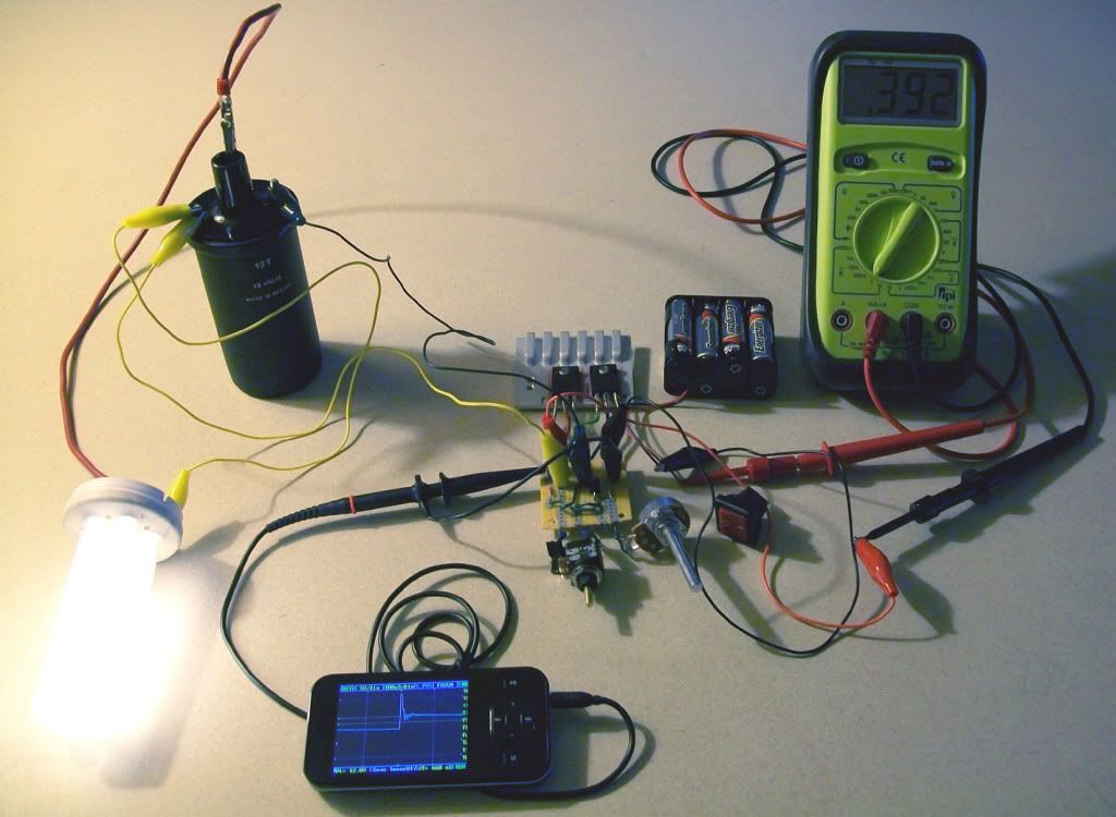
                    The sparks were fun, but this lights a fluorescent light bulb rather dimly:

                    Last edited by Godfrey; 10-24-2010, 05:36 AM. Reason: corrections

                    Comment


                    • #70
                      Originally posted by penno64 View Post
                      Runs as low as 3.0v and screams at 12v.
                      Great .

                      Originally posted by penno64 View Post
                      Sorry guys, it is charging. I was biting off more than I could chew. I was trying to charge a 12v.
                      On a 1.2 Ni-Mh, charges and rather quickly too.
                      That is what make me wonder if it really radiant. Normal stingo can charge 12V battery with 3V source.

                      Originally posted by Godfrey View Post
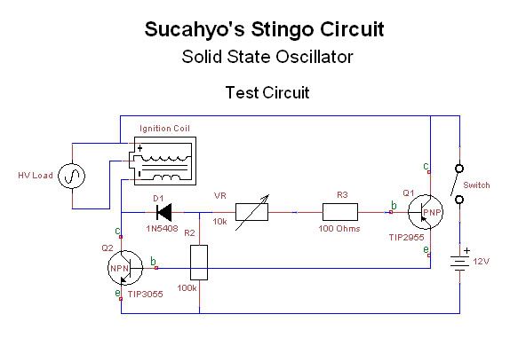
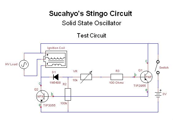
                      The primary coil is connected in series directly with the secondary, so the positive terminal appears to be the base/tap in the middle. I reworked my ingnition coil symbol to reflect, schematically, what's going on, like so in this latest test circuit:

                      Healhty .


                      Originally posted by Godfrey View Post
                      Here's a nice spark from the + terminal to HV:
                      You use 3V for spark and neon bulb?

                      Comment


                      • #71
                        Godfrey,

                        I tried the last circuit you posted.

                        Though I left the HDD motor connected, I was still able to connect the car coil
                        and get sparks.

                        Thanks so much, this small ciruit is definately fun.

                        I wonder how this would go driving my slayer coil ?

                        One way to find out.

                        I am learing how to reduce the size of video so I can post to you tube.

                        Kindest Regards, Penno

                        Comment


                        • #72
                          Originally posted by Sucahyo
                          I get brighter neon with my transformer than my car coil.
                          Keep meaning to ask what transformer you get the most power out of. Can it light a fluorescent bulb brightly?

                          Originally posted by Sucahyo
                          If your coil is not oil filled, maybe you can fill it with oil.
                          Yes it is filled w/oil.

                          Originally posted by Sucahyo
                          But add at least 100 ohm between the PNP and potentiometer to prevent you from burning up the PNP.
                          Originally posted by 7imix
                          I've built a few of these, sometimes I use a 1000 ohm resistor and sometimes I use a 100 ohm.
                          Originally posted by 7imix
                          Here's the post I built my first sparker from.
                          Thanks for the info, 7imix!

                          Originally posted by Sucahyo
                          No. To be sure I retry it again with complete circuit today. With car coil the neon bulb is brighter when the secondary is shorted. and I recall that with analog volt meter my air core transformer give the opposite result, less output voltage with shorted secondary. I think the core type can change result.
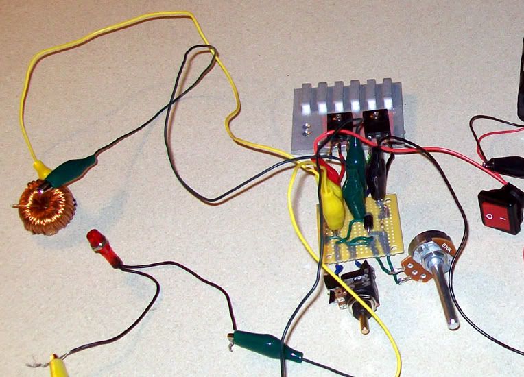
                          I can get my little transformer and this toroid coil to work on either of my Stingo circuits at around 6V. Neither works the very instant I short the secondary. The instant I open up the secondary, the oscillations start again. I can run a load on the secondary like a neon and everything works fine:


                          Originally posted by Sucahyo
                          YouTube - Stingo shorted secondary experiment


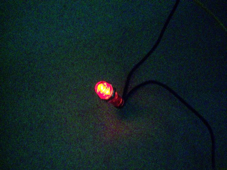
                          The output barely lights a neon bulb:


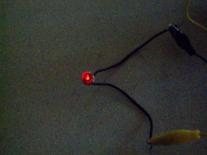
                          Lights a neon brightly:


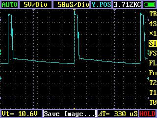
                          It oscillates at about 3.6 kHz and the wave looks like so:


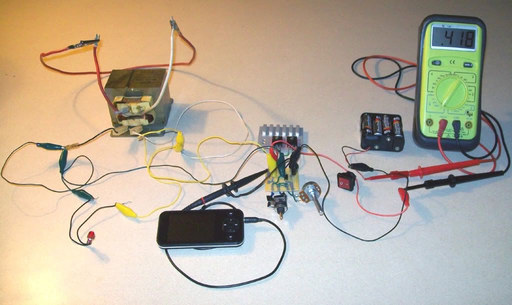
                          I made a first go at a MOT, which I was able to get oscillating with the secondary shorted:


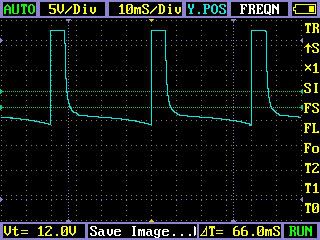
                          The output barely lit a neon. The MOT can oscillate very slowly and gets this kind of wave form:


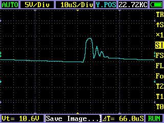
                          With the secondary open, it optimizes at 22.7kHz with a completely different shape:


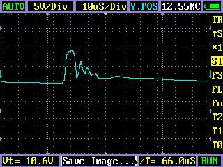
                          Shorted secondary, no dial change and we have almost the same waveform, but about half the frequency:

                          Originally posted by penno64
                          I tried the last circuit you posted.
                          Originally posted by penno64
                          Thanks so much, this small ciruit is definately fun.


                          Originally posted by penno64
                          I wonder how this would go driving my slayer coil ?

                          One way to find out.
                          That would be cool to see. Go for it, dude!

                          Originally posted by penno64
                          I am learing how to reduce the size of video so I can post to you tube.
                          Looking forward to your video posts!

                          - Godfrey

                          Comment


                          • #73
                            Originally posted by penno64 View Post
                            I wonder how this would go driving my slayer coil ?
                            I just built a slayer coil last night. First I am going to build the normal slayer circuit, then I am going to try it with stingo.

                            Yes it just adds minimum resistance. That's interesting that the transistor is still hot even with the resistance turned up...


                            Originally posted by Godfrey View Post


                            It oscillates at about 3.6 kHz and the wave looks like so:

                            Nice looking spikes.

                            Originally posted by Godfrey View Post
                            I made a first go at a MOT, which I was able to get oscillating with the secondary shorted:

                            Nice idea trying a mot. I'll go look for a microwave today to try this.

                            The iron core is preventing the transformer from oscillating quickly. I'm betting air core coils like the slayer coil are going to be best for our purposes.

                            The key to getting real power with any impulse circuit: rise as steep as possible, pulse as short as possible, fall as steep as possible, and frequency as high as possible, preferably the resonant frequency of the system. Just go look at any electronics textbook where they graph voltage and current over time during charging and discharging a capacitor and inductor.

                            Someday soon I am going to do a big blog post with some graphs and actual numbers.

                            watts = volts * amps, so with ac current the amps are often canceling out the volts and vice versa. With impulse currents the volts and amps are both maximized at the same instant. One has to average in the time that the circuit is off as well, so increasing the frequency (assuming the pulse duration remains the same) increases the overall duty cycle.

                            Don smith suggests the following equation:

                            E = (Volts * Amperes) * Frequency^2

                            Moving to air core coils and increasing the frequency is likely to help boost the useful output quite a bit.

                            Great idea dude. I see you are isn't a lot of the same radio shack parts I have used in the past

                            Thanks to everyone putting energy into this thread

                            Thanks to everyone who has a dream of clean energy systems

                            Comment


                            • #74
                              Battery Desulphating

                              Originally posted by 7imix View Post
                              I just built a slayer coil last night. First I am going to build the normal slayer circuit, then I am going to try it with stingo.


                              Yes it just adds minimum resistance. That's interesting that the transistor is still hot even with the resistance turned up...


                              Nice looking spikes.


                              Nice idea trying a mot. I'll go look for a microwave today to try this.

                              The iron core is preventing the transformer from oscillating quickly. I'm betting air core coils like the slayer coil are going to be best for our purposes.


                              The key to getting real power with any impulse circuit: rise as steep as possible, pulse as short as possible, fall as steep as possible, and frequency as high as possible, preferably the resonant frequency of the system. Just go look at any electronics textbook where they graph voltage and current over time during charging and discharging a capacitor and inductor.

                              Someday soon I am going to do a big blog post with some graphs and actual numbers.

                              watts = volts * amps, so with ac current the amps are often canceling out the volts and vice versa. With impulse currents the volts and amps are both maximized at the same instant. One has to average in the time that the circuit is off as well, so increasing the frequency (assuming the pulse duration remains the same) increases the overall duty cycle.

                              Don smith suggests the following equation:

                              E = (Volts * Amperes) * Frequency^2

                              Moving to air core coils and increasing the frequency is likely to help boost the useful output quite a bit.


                              Great idea dude. I see you are isn't a lot of the same radio shack parts I have used in the past

                              Thanks to everyone putting energy into this thread

                              Thanks to everyone who has a dream of clean energy systems
                              Originally posted by sucahyo View Post
                              The goal is to maximize output current first, and then minimize the input current. But that is optional, you can also choose higher output instead of highest efficiency.


                              For charger I use computer power supply toroid. As for the coil spec, I don't know, sorry:


                              FWBR in series with cap is what I get after some experiment. You will get 40%. You can add another 20% with a trick but I am still not sure if it will be good for the battery.

                              Try with water surface too or increase the input voltage to 24V or something.

                              Thanks for the video . I really love the spike reading . Show sign of h wave too .

                              Can you show scope reading with shorted secondary and your hand toucing the PNP base?

                              I see delta T as 300uS, for small or big grid? that means the spike width is around 50uS or something?
                              Sucahyo, -thanks for the great circuit.

                              Godfrey, Penno64 , 7imix .-- Great inputs with this circuit.

                              Can I ask all of you if the Stingo charger will actually charge/desulphate a run down battery of sorts.
                              I have built a couple of different charging/desulphating circuits which have various pros and cons to them which are much to be desired.
                              This circuit just might be the ticket though. Any comments will be appreciated.

                              I'm going to go ahead and get the parts tomorrow and build one anyway but was just curious in the mean time. I'll let you know how I make out with mine.
                              Thanks again for all your inputs -great info here.--PAR

                              Comment


                              • #75
                                Originally posted by Armagdn03 View Post
                                Why did you choose to call your circuit's "stingo"?
                                I get stinged when I put my hand in the circuit. It is now the location of 500K resistor. This circuit can put out 1000V which can hurt a lot ......

                                Originally posted by penno64 View Post
                                I wonder how this would go driving my slayer coil ?
                                I will look forward for that . From 7imix result too .

                                I suggest that secondary and primary common terminal connected to battery positive. Just in case of headache.

                                Originally posted by Godfrey View Post
                                Keep meaning to ask what transformer you get the most power out of. Can it light a fluorescent bulb brightly?
                                My best is 3 watt but I have problem replicating it. using 9V/230V 1.9A transformer of an old motorola modem adapter. This is full brightness.
                                YouTube - 3 watt CFL ligther with sting oscillator

                                Correct voltage multiplication is critical it seems.


                                Originally posted by Godfrey View Post
                                My TIP/31/32, small transformer circuit runs very cool at 3V – 4.5V, but the transistors heat up fast at 6V – 9V. Adding the 100 ohm resistor in series with the 10k potentiometer helped cool down the PNP a bit, but the NPN still ran very hot, quickly. I didn’t try a 1k yet, but really: doesn’t it just add more minimum resistance? When I turn up the 10k pot, the transistor heating problem does not go away.
                                I get hot NPN too. I use heatsink and sometimes with a fan. Robert Adams motor is a case where the transistor heat is exceeding input. So I think hot transistor is not really a bad sign.

                                Originally posted by Godfrey View Post
                                Thanks for the video, but I can’t make out how you’re shorting your car coil? Can you show me a photo of your car coil configuration?


                                We lit the neon using coil collapse current of the primary. Same thing with charged battery or other load.

                                BTW, I found out that I get brighter with shorted secondary only with minimum base resistance (100 ohm).


                                Originally posted by Parav View Post
                                Can I ask all of you if the Stingo charger will actually charge/desulphate a run down battery of sorts.
                                I have built a couple of different charging/desulphating circuits which have various pros and cons to them which are much to be desired.
                                My charger now consist of two stingo and one imhotep relay charger. Charge a depleted 2500mAh nimh in an hour.

                                As for desulphating, at least mine broken during over use, not during charging. Keep in mind that we can't restore a badly corroded battery. I have some success with nicad and nimh.

                                I now modified the FWBR part a little:

                                Comment

                                Working...
                                X