This forum is preserved as a permanent archive. The community continues at eMedia Press.

Announcement

Collapse
No announcement yet.

Stingo Solid State Battery Charger

Collapse
X
 
  • Filter
  • Time
  • Show
Clear All
new posts

  • #16
    I did some measurements on the spike duration. On my first coil with the secondary shorted and no load, the spike duration was 12usec. The highest voltage on the low voltage side was 29 volts as calculated by my meter, but it must be performing rms calculation on it because the scope is way off the charts on the spikes. The scope goes to 100 volts. The voltage fell off as i adjusted frequency to either side, so I figure that must be the resonant frequency of the coil. The frequency is 7.5khz.

    On my other coil, I couldn't get it to oscillate with the secondary shorted. With the secondary open, the spike had a much gentler downslope and the spike duration was therefore 70us. The peak voltage was 45 volts and the resonant frequency was 1khz.

    Comment


    • #17
      Originally posted by 7imix View Post
      I did some measurements on the spike duration. On my first coil with the secondary shorted and no load, the spike duration was 12usec. The highest voltage on the low voltage side was 29 volts as calculated by my meter, but it must be performing rms calculation on it because the scope is way off the charts on the spikes. The scope goes to 100 volts. The voltage fell off as i adjusted frequency to either side, so I figure that must be the resonant frequency of the coil. The frequency is 7.5khz.

      On my other coil, I couldn't get it to oscillate with the secondary shorted. With the secondary open, the spike had a much gentler downslope and the spike duration was therefore 70us. The peak voltage was 45 volts and the resonant frequency was 1khz.
      Can you tell us how you were able to adjust
      the frequency in order to find "resonance?"


      The "Stingo" circuit is a very good example of how,
      with a little creativity, a fairly simple and fun device
      can be put together with commonly available parts.

      If an automotive ignition coil isn't available then
      virtually any transformer with a low voltage secondary
      winding could be used in its place.

      Not only is the "inductive kick-back" of the driven
      winding useful; the high voltage produced in the
      "secondary" may also be "tapped into."

      Sucahyo has come up with a "stepping stone" to some
      very interesting possibilities for the experimenter.

      Comment


      • #18
        Originally posted by 7imix View Post
        I did some measurements on the spike duration. On my first coil with the secondary shorted and no load, the spike duration was 12usec. The highest voltage on the low voltage side was 29 volts as calculated by my meter, but it must be performing rms calculation on it because the scope is way off the charts on the spikes. The scope goes to 100 volts. The voltage fell off as i adjusted frequency to either side, so I figure that must be the resonant frequency of the coil. The frequency is 7.5khz.
        Thanks. I am not sure if it is resonance frequency of the coil, It maybe just the resonance of all component. Try it with load too.

        Originally posted by 7imix View Post
        On my other coil, I couldn't get it to oscillate with the secondary shorted. With the secondary open, the spike had a much gentler downslope and the spike duration was therefore 70us. The peak voltage was 45 volts and the resonant frequency was 1khz.
        Thanks. You may need to try to replace the 100K resistor with potentiometer.

        I found that different coil or load need different combination of all three resistance.

        Comment


        • #19
          Originally posted by SeaMonkey View Post
          Can you tell us how you were able to adjust
          the frequency in order to find "resonance?"
          When the potentiometers in the stingo circuits are changed, the frequency of impulses going into the coil changes. In The borderlands video "transverse and longitudinal waves" Eric Dollard demonstrates how sending the output of an audio waveform generator through a power amp through a coil at certain frequencies causes it to reflect at a certain phase. When the phase of the reflection from the coil matches the phase of the audio output, the system is in resonance and the voltage is at it's maximum. When the frequency increases or decreases from this point the voltage drops.

          Check out the Eric dollard videos if you haven't seen them, they are amazing.

          Comment


          • #20
            Originally posted by sucahyo View Post
            Thanks. I am not sure if it is resonance frequency of the coil, It maybe just the resonance of all component. Try it with load too.

            Thanks. You may need to try to replace the 100K resistor with potentiometer.

            I found that different coil or load need different combination of all three resistance.
            Yes, its the resonance of all components. With load the frequency range available is different and the resonant frequency is different.

            I'll try a pot.

            Thanks!

            Comment


            • #21
              Last edited by Godfrey; 10-03-2010, 04:42 AM.

              Comment


              • #22
                Originally posted by 7imix View Post
                Yes, its the resonance of all components. With load the frequency range available is different and the resonant frequency is different.
                I forgotto add. Try to change the 1K resistor with 100 ohm. hotter transistor but will force oscillation more.

                Originally posted by Godfrey View Post
                Is it possible, Sucahyo, to remove the coil and isolate the oscillator part of the circuit for testing with 1x probes to see the square waves? Or is the coil necessary for oscillation to work?
                Yes, the coil is necessary. Can't you test it on PNP output?

                Comment


                • #23
                  You're welcome. Glad you like the DSO Nano. I like it a lot. We should get sucahyo one

                  I'm not actually using HV probes with the scope. I hook it up to the low voltage side. The spikes go way over it's range, but as long as the spike is nice and short I believe it won't hurt it. Mine is still working fine after using it a lot in this way.

                  i have a fluke HV probe. They have a 4000V one (100V divider) and a 40000V one (1000V divider). I have the 40000V one. It's just a voltage divider with a really big resistor in it. It wouldn't be too hard to make one assuming you can find a really huge resistor. Can probably find one in a microwave or buy one online. The voltage divider resistor goes to ground.

                  Originally posted by Godfrey View Post
                  I was able to see square wave output and measure frequency from a 555 timer circuit right away. I tried capturing wave output to Micro SD card to work but was not able to get it to work. Have you had any luck with data storage? The documentation seems pretty sparse. Is there a good website for more information on it?
                  You have to create files of the appropriate name on the SD card before you can save to those files. It's able to save to files, but not create them. Lame. Read the docs, it's in there.

                  The coil is what makes the whole thing oscillate... Try finding a brushed DC motor and making the motor stingo variant, the coil is a lot smaller and therefore so are the spikes.

                  But, don't worry, I've measured a lot of HV spikes with it and haven't had problems. As long as it's not DC or sine wave AC high voltage I'm guessing it will be fine.

                  Take some pictures and some video of your setup

                  Comment


                  • #24
                    Originally posted by sucahyo View Post
                    I forgotto add. Try to change the 1K resistor with 100 ohm. hotter transistor but will force oscillation more.
                    Cool, thanks. Weren't you suggesting I replace the fixed resistor with a potentiometer though?

                    Comment


                    • #25
                      Originally posted by 7imix View Post
                      Cool, thanks. Weren't you suggesting I replace the fixed resistor with a potentiometer though?
                      Two suggestion. Replacing 100K with potentiometer, and replacing 1K with 100 ohm.

                      Comment


                      • #26
                        Originally posted by sucahyo View Post
                        Two suggestion. Replacing 100K with potentiometer, and replacing 1K with 100 ohm.
                        Great, thanks for the clarification.

                        Comment


                        • #27
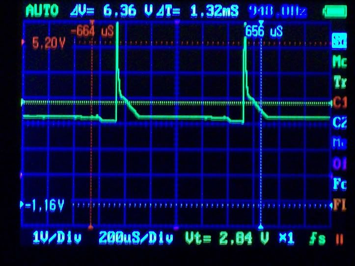
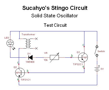
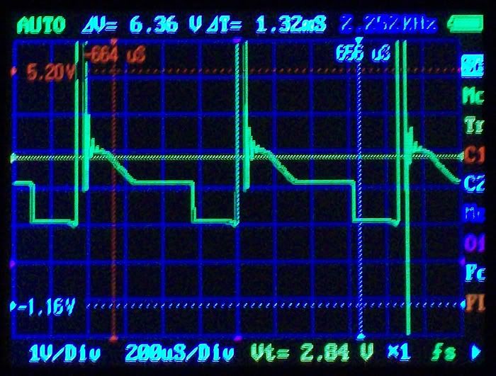
                          3V test circuit wave forms

                          Originally posted by 7imix
                          You have to create files of the appropriate name on the SD card before you can save to those files. It's able to save to files, but not create them. Lame. Read the docs, it's in there.
                          Originally posted by 7imix
                          Read the docs, it's in there.
                          Originally posted by 7imix
                          Take some pictures and some video of your setup
                          Originally posted by 7imix
                          The coil is what makes the whole thing oscillate... Try finding a brushed DC motor and making the motor stingo variant, the coil is a lot smaller and therefore so are the spikes.


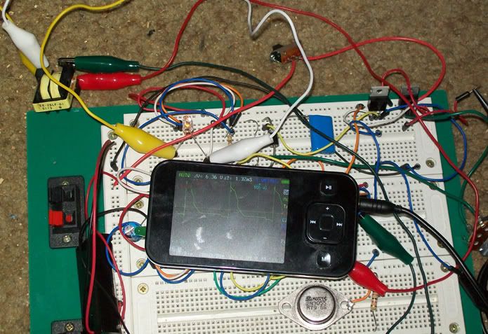
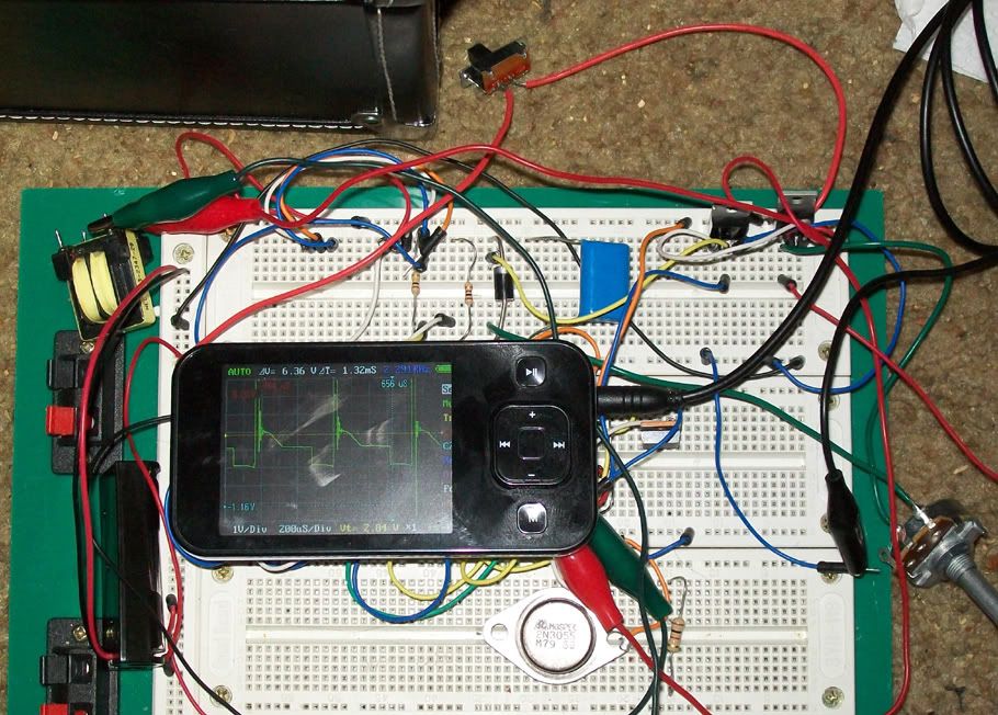
                          My setup:


                          Knob right - highest resistance /lower frequency:


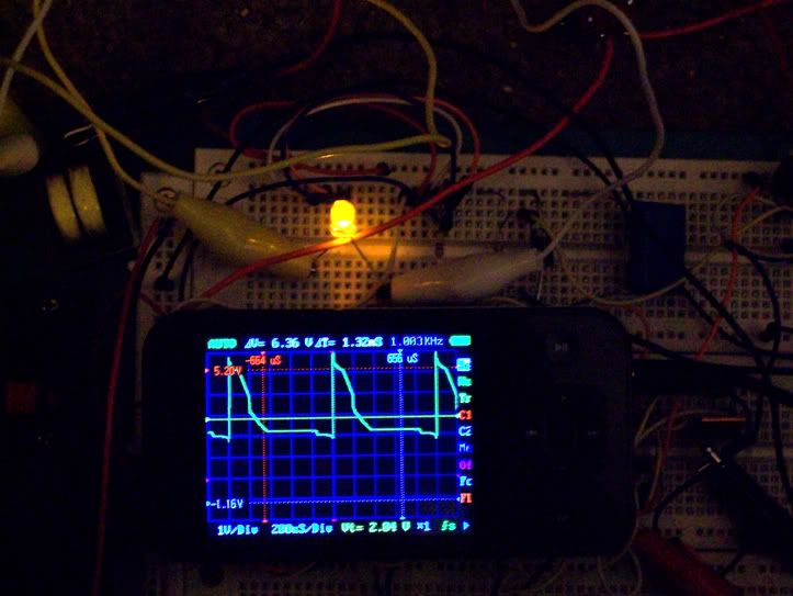
                          It oscillates with an LED across the secondary. The LED lights dimly:


                          Greatest brightness fine-tuned 2/3 up the knob, oscillating at 1kHz:


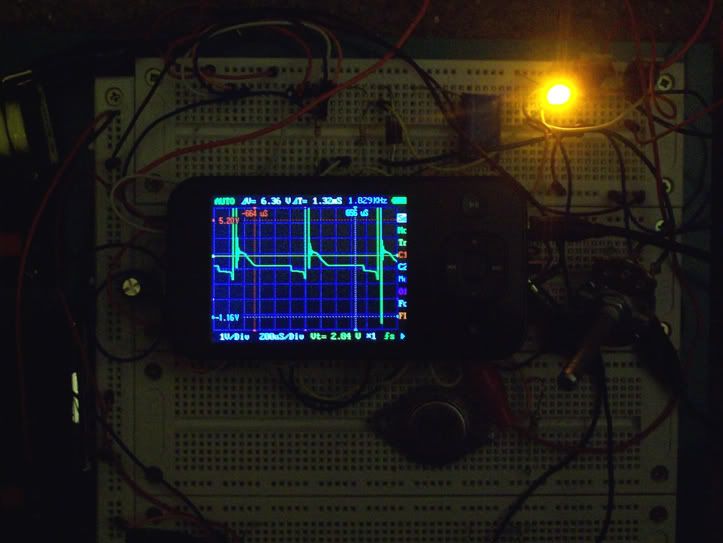
                          When the LED is the regular load, it burns so brightly that it hurts to look at directly:


                          Greatest brightness fine-tuned within first 1/3 of knob, oscillating at 1.78kHz:

                          Last edited by Godfrey; 10-03-2010, 04:22 AM.

                          Comment


                          • #28
                            Multi Stingo Circuit?

                            Originally posted by Sucahyo
                            BTW, as charger, I prefer multiple stingo combined with my FWBR combiner than single stingo
                            Keep meaning to ask you how that circuit would look. Are you just talking about two Stingos joined at the output to an FWBR? Or something more complicated?

                            If more complicated, do you have a schematic to show?

                            - Godfrey

                            Comment


                            • #29
                              Thanks for the scope shot .

                              Originally posted by Godfrey View Post
                              For now, I was able to get a smaller transformer from a computer power supply working with 3V (2 AAA batteries). Here is a schematic showing an LED as the load:

                              Are you sure you don't put the LED backward? I think you should get brighter LED or even kill it if you reverse it. Mine reach 50V.


                              Originally posted by Godfrey View Post
                              Keep meaning to ask you how that circuit would look. Are you just talking about two Stingos joined at the output to an FWBR? Or something more complicated?
                              Complicated. Here is an example of combining two:


                              Three:


                              Ignore the circuit, just put attention to the wire after the coil going to charged battery.

                              Comment


                              • #30
                                I have firmware version 2.02. I haven't tried actually saving any waveforms yet, I'll try it and let you know if it worked.

                                What clone do you have?

                                Awesome, great shots, thanks.

                                Yeah you need to use brushed motors. Computer fans have a little board that actually generates ac to drive the motor. Try a cheap toy, like maybe some rc slot cars or something.

                                Thanks for the idea about using a smaller transformer. I played around with this a bit and enjoyed it a lot. I will do some more detailed measurements and report about them tomorrow.

                                I finished my fourth stingo build yesterday. I'll take some pictures and post them soon. It came out very nice and compact. I'm going to wind an air coil for it and see how high the frequency can go. I can't decide how to wind the coil yet... Bifilar pancake coil I think.

                                Comment

                                Working...
                                X