
 Tweet
Tweet
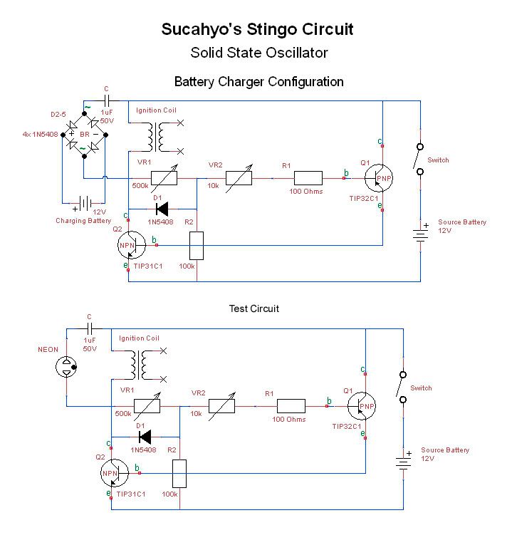
-
 Last edited by Godfrey; 09-27-2010, 04:01 AM.
 -
It suppose to lit but you don't need capacitor. You have to put atleast a diode if you intend to charge battery.Originally posted by Godfrey View Post
My capacitor is rated for 250V too.
Yes. I wound my coil without secondary. For safe operation, short the secondary.Originally posted by Godfrey View Post
From 3V to 24V, what ever you have and what ever output you need.Originally posted by Godfrey View Post
Above audible range down to 50Hz depend on load, coil and resistor value.Originally posted by Godfrey View Post
Sorry, I can't explain it either. I found it by accident. That is more efficient than using the PNP in a normal way. Harvey suggest an SCR to replace it but for me, TIP32C is more obtainable and cheaper.Originally posted by Godfrey View Post
To increase efficiency, to prevent too much normal electricity flowing to the load.Originally posted by Godfrey View Post
In my opinion, the spike is bouncing, so by using FWBR I get the weaker reverse bounce too and I use capacitor to prevent the load from getting powered by the source battery.
I am using same circuit to charge any kind of battery between 1.5V to 12V. I don't think you can make 1.5V nicad overheat if you only use one stingoOriginally posted by Godfrey View PostLast edited by sucahyo; 09-27-2010, 06:17 AM. -
The PNP Transistor is connected to operate in whatOriginally posted by sucahyo View Post
is known as "inverse mode." The Collector is functioning
as the Emitter and the Emitter is functioning as the
Collector.
By working in "inverse mode" it effectively reduces the
base drive to the NPN Switching Transistor thereby
preventing it from being overdriven.
The Current Gain (Beta) of a transistor in inverse mode
is approximately 10% of normal gain.
To attain the same effect with the PNP Transistor
in normal mode a variable resistor could be connected
in series with the NPN Base lead in order to "tune"
base drive for maximum efficiency.
There is nothing wrong with "inverse mode" operation.
It is seldom used but a good "trick" to remember when
it can be taken advantage of.Comment
-
Godfrey, thanks for starting this thread, and sucahyo, thanks for discovering the stingo. :-)
The stingo is absolutely my favorite thing to experiment on, and I anticipate it will continue to be. I have had so much fun building a couple and experimenting with them. The stingo sparker is my favorite. I have tried replicating the modification with a brushed dc motor but I don't have exactly the right parts and it is not working as it should.
I have been performing some measurements with my little scope and my nice new high voltage probe. With the spark gap running I have measured up to about a megahertz. With no load I was able to get way up high above audible range, something like 25mhz. I will measure again and take more accurate notes.
I measured about 2000 volts off the high voltage side, which seems a bit low to me. I will go back and double check my measurements. Also, I measured about 800 volts with the probe just in the air, a few feet away from the apparatus! It diminishes as I move the probe radially outwards. I will take a movie of this. It's quite interesting.
I also did some experiments hooking up some capacitors and bars, hairpin style. I was able to get it to light a couple of neon bulbs. Will definitely do more experiments with this! Awesome.
I need to get my camera charged and take some video. I have lots of observations to share.
Thanks again sucahyo! Your circuit is great!Comment
-
Hi All,
Thanks for your posts Sucahyo. I forgot to ask you about the knobs. What do the two potentiometers control. I assume one is for frequency, but not sure which.
Originally posted by SucahyoOriginally posted by SucahyoI agree. Coil ringing may be a factor too.Originally posted by Sucahyo
Good idea to use FWBR!Originally posted by Sucahyo
So the cap is a DC filter? What load are you talking about? The charging battery?Originally posted by Sucahyo
Thanks so much for that very helpful information, SeaMonkey!
Originally posted by 7imixComment
-
All potentiometer change frequency. But each have different most efficient position that change with the load. If you have two amp meter, you can know the position on spesific load.Originally posted by Godfrey View Post
I wound it my self to make it small. Any coil can be used. My best is air core but what I use to charge battery is the small toroid one.Originally posted by Godfrey View Post
I don't know. I suggest to short the HV output for safety. The output should reduce a bit but see if you get it too.Originally posted by Godfrey View Post
Notice that you can only get radiant output with shorted secondary with stingo. On any other radiant circuit you must let the HV output open to get radiant output.
Yes and yes.Originally posted by Godfrey View Post
Yes. Sometime I can not hear it's whine. Usually when charging an empty battery.Originally posted by Godfrey View Post
BTW, as charger, I prefer multiple stingo combined with my FWBR combiner than single stingo. Efficiency of combined circuit: 1 + 1 > 2.Last edited by sucahyo; 09-28-2010, 06:54 AM.Comment
-
Where do the meters go? When the meters are in place, is the goal to maximize current?Originally posted by sucahyo View Post
What is the diameter, how many turns, and what gauge wire for your best coil? I will make one. I wanted a smaller coil to make it easier to put in a project box.Originally posted by sucahyo View Post

Comment
-
@sucahyo
Have you tried to connect the negative of the battery to the positive of the source? Disconnect the negative on the FWBR and connect it to the positive of the power source. See if you get an increase, decrease or same current for both draw/input.
EcomanLast edited by Ecoman11; 09-28-2010, 05:29 PM.Comment
-
If you are not watching this other thread yet, it's another stingo variant, and I made some progress reproducing it today, so check it out. There's a movie of some cool results.
I also took some video of the stingo sparker and the stingo running with the high voltage side of the car coil shorted. It's uploading right now, I'll post a message when it's done processing.Comment
-
Ok, here is the first of a series of videos showing measurements of one of my stingos.
YouTube - Stingo Spark Gap Measurements
The frequency range I was able to measure is about 800hz to 5.5khz.
With the gap the spike is a lot dirtier, with a lot of bounce after the initial spike. I may not be getting a DC spark. Perhaps my magnetic quencher is in the wrong orientation, or the magnets are not close enough. I will experiment some more.
In the next video I perform measurements with the high voltage side shorted instead of a gap, and the spikes are much cleaner.Comment
-
The goal is to maximize output current first, and then minimize the input current. But that is optional, you can also choose higher output instead of highest efficiency.Originally posted by 7imix View Post

For charger I use computer power supply toroid. As for the coil spec, I don't know, sorry:Originally posted by 7imix View Post

FWBR in series with cap is what I get after some experiment. You will get 40%. You can add another 20% with a trick but I am still not sure if it will be good for the battery.Originally posted by Ecoman11 View Post
Try with water surface too or increase the input voltage to 24V or something.Originally posted by 7imix View Post
Thanks for the video . I really love the spike reading
  . Show sign of h wave too .
Can you show scope reading with shorted secondary and your hand toucing the PNP base?
I see delta T as 300uS, for small or big grid? that means the spike width is around 50uS or something?Comment
-
thanks, I am looking forward to trying this.Originally posted by sucahyo View Post
Ok, I will just wind a few coils and try them out. ThanksOriginally posted by sucahyo View Post
You are welcome. What is an h wave?Originally posted by sucahyo View Post
Here is the second video I made today, of the secondary shorted. I will film touching the base tomorrow.
YouTube - Stingo with shorted secondary
At the top it says 50usec/div. Those are the grey squares on the screen. Delta t is the measurement between the two white dotted lines, which I can move to measure things. I will measure the spikes that way tomorrow.Comment
-
h wave is a Bedini suggested wave form for charging a battery. A spike and some current after that.Originally posted by 7imix View Post
Thanks. It do look noise free. I guess the secondary coil have some influence on the primary. I wonder if secondary noise is actually gain?Originally posted by 7imix View Post
ThanksOriginally posted by 7imix View Post.
Comment


Comment