-
-
You can think whatever you like buddy!
I f@cking do and I'm not going to stop shouting about it!
Very soon I won't be the only one shouting about it either.
Then you can think like we do! 

Comment
-
If I'm not mistaken, Bruces circuit does use an earth ground as well as an antenna to create a charge separation and ultimately a potential difference within the system - at least the ones I've seen and studied to date.Comment
-
I greatly respect your work Lenz. I'm sorry I haven't had time to finish illustrating your work yet. Please bear with me.
Please remember you have 1st Edition of the manual and you were one of the first in the world to receive it, so I take my hat off to you for being there at the birth.
The 2nd Edition, your free upgrade hadn't been finished at the time you received it.
You are in line to be in a very unique position but things have not aligned enough yet for you to realise it.
Some of you have experienced NSTs burning out and some of you talented guys are now making your own.
Check out this beast:
Ion Pump
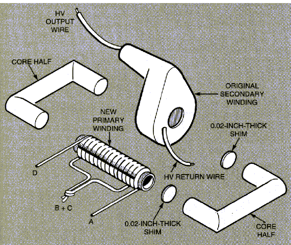
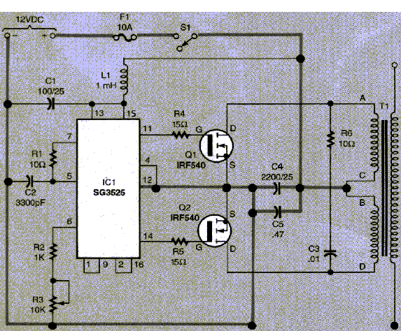
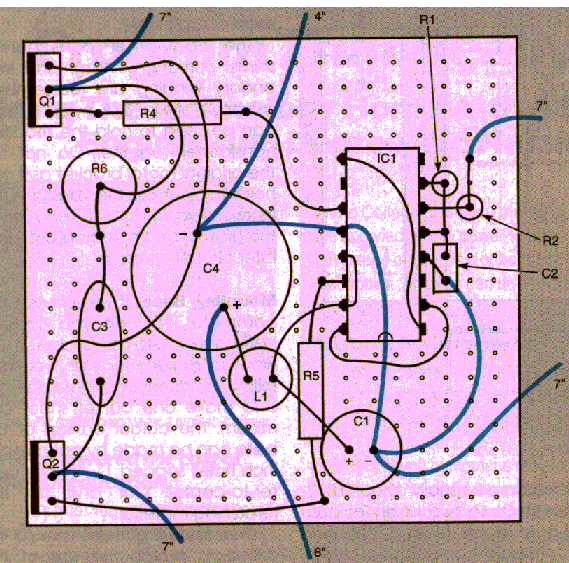
Not enough...... why not try a 500kv Tesla coil instead of your NST!
How much power do you want?Comment
-
Tuning
How would you tune this device?Originally posted by qwekw View Post
Does it apply to zilanos version?
Just curious
Ged.Comment
-
[QUOTE=soundiceuk;188587]I greatly respect your work Lenz. I'm sorry I haven't had time to finish illustrating your work yet. Please bear with me.
Please remember you have 1st Edition of the manual and you were one of the first in the world to receive it, so I take my hat off to you for being there at the birth.
The 2nd Edition, your free upgrade hadn't been finished at the time you received it.
Hi soundiceuk,
Thanks for the info.
Actually I'm new about this forum and realized that this forum have a very talented and generous persons to share their knowledge and skills with us.
BTW..where we can buy or obtain those manual..?!
Thanks
saharsComment
-
I would post direct link but I'm on my phone.
SonoMagnetics™ - Home Page
"Direct Electrical Power from The Utilization of Earth IONS".
Send your invoice to admin of Log in for further instructions.
Thank you!Comment
-
Already purchase that book. Thanks for the info.Originally posted by soundiceuk View Post
Regards
SaharsComment
-
queries about Don Smith device
Hello everyone,
I am experimenting trying to replicate the most famous Don Smith design (the one commented by Zilano before). I want to explain some possible theories about its operation so maybe you can give me your thoughts:
The circuit works when L1 enters into resonance with L2, and their respective capacitors. The result is that the admittance produced between the capacitor and L1 is close to 0 mho, that is an open circuit, so the voltage in the coil is maximum, which makes the inductive impedance value of the coil to be low, which give us a very high reactive power in the coil. I have been able to measure these effects so far with the original 5 turn L1, not with the recently published 80 turn L1.
Now, one theory I manage is that when L2 enters into resonance with its capacitor, the reactive power in L1 is induced to L2 and is converted back into active power (a very high one), giving us a lot of useful power.
The other theory is that the very high power we will obtain in L2 is still reactive, but even if reactive power is not capable of lighting a bulb, it will charge batteries or capacitors (John Bedini said this in a blog I read some time ago)
In none of these theories I have a clue where the additional electrons come from and in what part of the process (do they come from the earth grounding in the secondary part of the circuit?)
What do you think?
Anyway, disregarding if any of the theories above is correct, I have some construction issues that somebody may be able to help me with:
1. The losses of the first part of the circuit are too high. When I use a 12volt battery connected to a neon tube driver PVM12 or PVM500 of Information Unlimited - Science Projects, Electronics Kits, Lasers, Tesla Coils, High Voltage Engineering, Plans, Books, Parts, KitsComment
-
Originally posted by zilanoComment
-
Alien device
Hi Zilano about capacitor can I use an MO cap? What is the inverting circuit just an inverter?Originally posted by zilano
Thanks for sharingComment
-
All notions regarding cap is - it needs to be high capacity fitting to the power drawn. It's like a capacitor at an AC motor.
@ALL: Apart that I built this night my first HV pulse capExperts spend hours a day in order to question their doing while others stopped thinking feeling they were professionals.Comment
-
Replication of woopy karcher with incandescent light bulb
Laurent, I replicated your icandescent bulb experiment, see the attached photos and circuit.Originally posted by woopy View Post
My results:
Little incandescent bulb at 3 Volt and 0.25 A --> 0.75 Watt very bright (control test with power supply).
Input to kacher 10V 0.1 A --> 1 Watt, little incandescent bulb not so bright as in control test with 0.75 Watt. (Accurate measurements not yet done.)
My set up needs refinements. The primary has to be tested with different numbers of turns. Also the location of the primary (higher up or lower down on the secondary) has to be varied to find an optimum.
The iron wire loop (wire from an iron coat hanger) has to be placed almost at the top of the secondary.
The whole setup is very sensitive to the location of the primary, the location of the iron wire loop and the resistor between collector and base. When the resistor is too low (less than 2 K), the transistor becomes hot. When the resistor is just right, in my case somewhere between 4K and 10K (depending on the location of primary and iron wire loop), the transistor stays just warm.
I still have to measure the frequency and will do more tests and modifications when time permits.
There is a Avramenko Plug with three LEDs in series in the centre of the coil (see the photo with the glowing incandescent light bulb). The coil is made from cardboard and has a diameter of 255 mm. The secondary has 200 turns of 0,325 mm enamelled wire, the primary has two turns of 1.5 mm2 insulated copper wire; two turns seem to be not optimal.
Greetings, ConradLast edited by conradelektro; 11-05-2012, 01:20 AM.Comment
-
great replication
Great work Sir, I am pleased to see how fast you did this set up.Originally posted by conradelektro View Post
I suppose if you have variable caps you can re-tune whenever you move the loop.Have you considered multiple loops?
Best regards,
GaryComment
-
Hmmm?
Sir,Originally posted by soundiceuk View Post
In case I may have missed your promo, does the author have a working device?
GedComment

 Tweet
Tweet


Comment