
 Tweet
Tweet
Originally posted by kajunkreations
View Post
-
Yes, the natural resonance works much better and this is why N. Tesla calculated resonant frequencies by wire length. -
Ok, so do i use the L1 or L2 to set the desired frequency by wire length? and what frequency should the L1 with?Originally posted by T-1000 View PostComment
-
This one: Regarding recent Don circuits. Please note that the transistors in the inverter are drawn reverse. This is not meant as instructable.Originally posted by soundiceuk View Post
See first schematic in post: #3616.
The npn transistors are connected to + ?!?!??! Apart form not functioning this wil shoot the BE junction because there are 5 to 10V specified only.
~o0o~
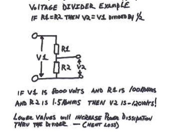
Regarding voltage deviders. Thanks for the hints. This will help some replicators for initial calculations.
For calculation in terms of common science it is OK. But do not expect to get there lots of amps out - like Don (40 KW). Your resistors will be in megawatt range. Calculate in LT spice! Resistors there are not power restricted.
So there seems to be something special with it. I add some notions I've red:
1. This strange cold energy prefers higher resistances unlike normal "hot" current. Nevertheless incandescent bulbs are lit. The neg energy will travel there to becaue it is easyer to pass. Think of 100mA current source being short circuited.
2. The primary winding of the inverter does not carry current. The neg. energy enrgizes it and the current occures at secondary only - where we intend to use it. Many replicators blew their inverter because they did't notice that before.
Please do not take that for true because I can not witness it. But this are some notion gatherd (sorry no link available) being able to possibly throw some light on the voltage deviders.This are some notions to ponder on.Last edited by JohnStone; 03-15-2012, 07:39 PM.Experts spend hours a day in order to question their doing while others stopped thinking feeling they were professionals.Comment
-
I quess if you guys are on the right track your going to reach the same conclusions ....Originally posted by dragon View Post Whatever you can do,or dream you can,begin it.Boldness has genius,power and magic in it.Begin it now.
Comment
-
Cap Wiring
Hi Folks,
as we have now some corrected Don circuits some of you will concentrate on these. I want to give you a hint regarding the correct wiring fo capacitors.
Please understand that every piece of wire is a resistance and an inductance as well. In normal life and tinkering this is mostly of no importance. Not so if we build Don's circuits. Independent if we wire the primary cap befor SG or the output cap - you have to obey some rules. Otherwise the cap will not work correctly.
left most diagram shows a very usual und extremely minor wiring. In order to understand the minority you should get the notion that as we deal with steep HV pulses and we intend to get very instantly enormous amounts of amperage.
Imagine: You sprinkle with a garden hose above a bucket and some droplets enter the bucket.
Basics:
Please understand that experets measured at a simple spark plug peak amps of 100 amps. No, not the coil delivers this amps but the charge is being accumulated in the ignition wires and the spark plug itself. At ignition event - bang - you have it - 100 amps for some nanoseconds. But this is essential in order to maintain a good spark later on . Did you get it? The charge is being accumulated! Not so in the most left diagram. One Ohm of tiny baby wires with alligator clips (all of you have it - is it?) corresponds to 100V at 100 amps. Some lazy charge will get there to in the capacitor but not as expected. And if you want to get it back you will get some lazy charge but not as expected.
2. The middle diagram shows a much mor better wiring. The current will be forced to visit the (hopely short) leads of the capacitor and will poor into it as it is easy now. Same as you get it out. You suffer only of one resistance while you have two in series in the 1st diagram.
Imagine: You sprinkle with a garden hose partly in a bucket and some serious amount will remain in the bucket.
3. The right most diagramm shows a very special wiring with a feed through capacitor. The current is forced to enter the capacitor and every electron energized will get the chance first to be stored there.
Imagine: You hold the nozzle of your garden hose directly into the bucket and will get back all water.
Explanation:
Please take in account that we inted to kick serious pulses even if the total amount of energy contained is small. Imagine a half pound hammer and you drive a nail into timber. This "tiny" hammer kicks with a forth of 8 tons - for short time. The nail prefers to displace himself. This is an example for a good build circuit.
Now get a hammer with a rubber protection above the metal. These are used in order to protect cobblestones when setting a pavement. You never will get 8 tons of forth - no shock. And any nail will laugh excessively if you try to hammer it with this tool into timber. This is an example of minor wiring.
So decide yourself what you intend to get! BTW: braided leads are the best. See one of Don's setup without coils. He used braided leads like the GND leads at your starter battery. He definitely knew why!
In summary: Designs for huge pulses need to be setup like high current setups. It does not matter if you require these pulses 1nS 1mS or constantly. Imagine what will happen if you connect your automotive starter motor with these tiny baby alligator clips. You will never get huge amps not for a nS nor for a pS. At these short time slices they never will burn nor get hot and you say: All connected - why does it not work? The problem might sit in front of the setup
PLEASE note and don't forget: At Don's circuits we have high current / high voltage designs!!!!!
Be careful if you buy havy HV capacitors. Most parts available are build for mains frequency only. For this application it is not essential if you have connected the complete roll of metal foil or only a part of it.
If you pulse these kind of capacitors only a small part of it will get the stress reqired in order to emit OU.
I have an idea how to build pulse capacitors with readily available material. Stand by. I will give information as soon I have proved it functioning.Last edited by JohnStone; 01-11-2013, 10:04 PM.Experts spend hours a day in order to question their doing while others stopped thinking feeling they were professionals.Comment
-
Absolutely marvellous John!
We should all watch at least the first 5 minutes of this:
Manly Hall - Magnetic Fields of the Human Body and Their Functions - YouTube
Any pain sufferers amongst us?
Pulsating Electromagnetic Field Therapy on Dr. OZ - YouTube
Here are some very rare texts. Cheers Google
The dark red and italic writing are different people but not Don.
When using electromagnetic resonate flux energy systems, the electro side, when used, dies the classic heat death. Not so with magnetic flux systems, which provide the classic amplification demonstrated - found in radio type devices. As the frequency increases the commutative result is a Fibnache multiplication of the energy present. The speed of gravity exceeded, it becomes radioactive, at the higher frequencies the Van Allen magnetic Belt is penetrated and the resonate magnetic flux travels onward through space. Off and on as found in high voltage - high frequency devices provides the required electron spin as the magnetic flux system source. Magnetic Flux Systems are not controlled - contained in the normal sense. Ungrounded transformers when exposed to resonate magnetic flux, change it to the classic useful electrical energy. We see this everyday when the electric power company uses their high voltage - high frequency system in transmitting energy into their distribution system. Typically they use from the source, 100,000 to 500,000 cycles per second, which the down line transformer system changes to the useful energy we recognize. Very high energy loss results from using lower frequencies when transmitting energy. This magnetic flux when transferred up stream by the transformer contains the amplified - greater output than input energy system which is written out of classic physics. J.P. Morgan and Thomas Edison doctored the physics books so that any effort in that direction would be said to violate the natural laws. If this is the case, the classic radio devices ever present could - would not exist. Earth grounding below 20,000 cycles per seconds provides current flow - amperage being volts times amperes, classic Watts.
Regards, Don Smith
The inverter can be done away with by using a capacitive transformer and a variable earth connection!!http://en.wikipedia.org/wiki/Telluric_current
I presume telluric potential is the same as resonating the ionosphere at the Schumann resonances to tap the same. This is pretty simple to do with a 555 IC and some pots for the R positions.
The interesting note about the transformers has peaked my interest as they are not physically attached... Presuming the transformers are capable of coupling with the radiant flux this seems it should work... this would work much better though if we used pancake coils to do away with needing to frequency match the output.
This is exactly what Don Smith has been telling people in so many words.
It is my understanding that "telluric currents" is generated when lightning strikes somewhere on the planet. They range from e.l.f. to rf. There are several frequencies that end on or around 6Khz.
Don,
In your experience, have you been able to obtain energy without the use of a spark-gap?
There are two kinds of energy [electro and magnetic] when used electric when earth grounded dies the classic heat death , how ever resonate magnetic flux is everywhere present throughout the universe , for example it's the source which spins the Earth at 1,000 miles per hour.
Since the weight of the Earth is known, the energy required to do this is known. This Energy is the Ambient Background everywhere present. Next step, transformers change magnetic flux into electrical flux which is useful energy. I have gone FAR, FAR beyond this stage and am already where you will be in about 20 years if you truly understand what you are doing.
Regards,
Don Smith
Don,
Please bring us up to speed with you. What you have learned will not do anyone any good if you take it to your grave with you. All of your work will have been done in vain and will be gone forever and will be as if never were. This is why I am open with my own work. I don't want my work to be all for nothing. Credit for my work will allow me to be immortal, in a sense of reality, at least for those who survive me.
Dear All, the Colleges, Universities and such with their Books are written with Special Interest controlling every word. Free Energy in Chemistry is that excess energy remaining after a reaction.
Examples are explosions of any sort including atomic, and many other reactions not here mentioned. The most obvious being our Sun and its Radiated Magnetic Flux - Solar Wind, which spins - rotates the Earth. There is no Free Lunch, only the form changes allowing
radiated energy to become available. A transformer changes radiated magnetic flux into usable electrical energy. Understanding these functions will be a start on Your Trip.
Ed Leedskalnin called this "other" energy magnetricity.
Coral Castle of Ed Leedskalnin

Comment
-
Kindly sent by Romero
"This is how this diagram should look like."

Comment
-
hehe i'd be lying if i said i really knew, but what im doing is:Originally posted by kajunkreations View Post
using 14 gauge 80 turn L2 half (62.8 ft is 15.66 Mhz)
so i type that into a conversion site and it tells me that the 1/4 wavelength is ...
...15.70 ft ... which happens to be the exact physical 1/4 wire length
Then i use a .005 uf cap for L1 which is now... 15.70 ft of 8 gauge
And after playing around, i found that L1 was significantly heavier than L2...
So i cut off 6'' at a time and re-weighed the coil, also stripping off the insulation and weighing that as well...
...to know the weight involved in the insulation to an accuracy of the 6'' increment,
then subtracted that from the total 15.70 ft
**you now have followed basic Tesla coil rules**
NOW, take an equal L2 and add that to the other side, (tapping it)
Now you have basically 2 back-to-back Tesla coils, and you only work in the midpoint of the one L2 half, the center-tap is neutralizing
now both halves of L2 are singing together well
Kind of like using 2 tesla coils tuned to eachother and duplicating the original
Like mentioned above, that will match nicely with NO tank caps on L2...
Its own self capacitance is enough
And adding ferrite will make you smile
Unless you really wanted to match the driver, BUT as Joe and others have found, REGARDLESS of the driver freq.... the values will be constant, only the spark needs adjustingLast edited by mr.clean; 03-16-2012, 02:25 AM.In the beginner's mind, there are many possibilities.
In the expert's mind there are few.
-Shunryu SuzukiComment
-
In the beginner's mind, there are many possibilities.
In the expert's mind there are few.
-Shunryu SuzukiComment
-
Hello soundiceuk This is really close too the circuit I'm currently using, Except I strongly suggest using a Variac (for AC) or PWM (dc) before the HV transformer, Flyback or HV source.Being able to controll the imput voltage on the transformer was a must for tuning mine...Originally posted by soundiceuk View Post
Randy
Comment
-
Comment
-
Try it yourself. Get an old professional foto flash device. Open the lead between the flash capacitor and the flash tube. Insert a coil. . Alternatively mount your coil on a cooking spoon made out of wood and attach longer leads.Originally posted by soundiceuk View Post
Shoot your pain area.Experts spend hours a day in order to question their doing while others stopped thinking feeling they were professionals.Comment
-
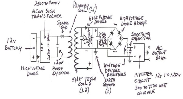
The free end of the bridge rectifier confuses me. Either we can omit both diodes completely or it is the input for an antenna. Any suggestions available?Originally posted by soundiceuk View PostExperts spend hours a day in order to question their doing while others stopped thinking feeling they were professionals.Comment
-
I had the same thoughts earlier... http://www.energeticforum.com/renewa...tml#post184404
If the NST ( 3) has a center taped secondary connected to earth ground then there is a return path and it functions like a buck converter. As drawn it cannot provide an output to the charging cap unless the diodes are "leaky" and providing a pulsed feedback. If there were an antenna at the DC- then it would entice the ambient to enter because of the spark gap. Maybe a large parasitic plate connected there would work as well.
I plan to do some experiments with that circuit when time allows, I have several HV DC modules that should provide a reasonable test bed.Comment
-
Pwm
What PWM are you using to the flyback? Do you have a schematic?Originally posted by Mr.Whip View Post
That circuit very interesting.
Regarding the voltage divider it should be to 12v not 120v for the inverter.
Ok thanks guysComment
Comment