This forum is preserved as a permanent archive. The community continues at eMedia Press.

Announcement

Collapse
No announcement yet.

Hubbard Coil

Collapse
X
 
  • Filter
  • Time
  • Show
Clear All
new posts

  • morpher44
    replied
    ccw

    Originally posted by dragon View Post
    morpher44... did you wind them all the same direction or is everyother one CW then CCW. I plan to cut some tube this afternoon but I wasn't clear on that point and wanted to make sure before I started winding...
    Looking from the top of the coil down I used CCW for all.
    I'm guessing that as long as all coils are same direction, that
    mutual induction will work most effectively.
    However, it may not make a noticeable difference.

    Leave a comment:


  • dragon
    replied
    morpher44... did you wind them all the same direction or is everyother one CW then CCW. I plan to cut some tube this afternoon but I wasn't clear on that point and wanted to make sure before I started winding...
    ________
    Last edited by dragon; 01-19-2012, 03:28 AM.

    Leave a comment:


  • morpher44
    replied
    ambient

    Originally posted by dragon View Post
    When time allows I will put together something similar to what you have to attempt some other tests and ideas. Like you said, if nothing else it may make a unique multi stage transformer....
    @dragon .. great. I look forward to seeing this....

    I think receiving "ambient" energy would certainly be
    the goal. I'm thinking there are enough lightning strikes
    around the planet .. and I read today on an astronomy
    website how certain frequencies are windows for energy
    since signals from the cosmos are NOT damped by the
    magnetic field and atmosphere in certain windows.
    One school of thought has high-energy in the high-frequency
    part of the spectrum.
    Yet we see devices like the Hubbard coil which clearly use
    ferromagnetic material and seem to be shooting for
    low frequencies and high Q.

    With large inductance, small capacitance, you can oscillate
    quite easily (Q is high)... and sustain for much longer. You just
    need a periodic PING of energy ... arriving in a high energy
    burst ... to re-sustain the oscillations.

    The waveforms I'm seeing seem to indicate that the ringing
    is damped as the signal's polarity is shifting from positive to negative.
    It is regenerative in the other direction from negative to positive.
    This low-frequency flux change appears to open and close
    windows of oscillation.

    The way I imagine this might work is the following.
    As the flux field enters the vicinity of the coil, the inductance
    in the coil is altered up and down its B-H curve.
    The dampening we see varies depending upon where we are
    on this curve for that inductor.
    There are certain parts of this curve were "gain" can
    be experienced ... ... or "amplification occurs".

    Before transistors ... there were magnetic amplifiers using
    coils to provide amplification. These were desirable over tubes
    for power & control applications -- hardened ... long lasting ... strong.
    Tubes were too fragile.

    Even today ... transistors are cheap yes, but they are very
    low impedance devices ... easily fried ... not long lasting ...
    also fragile.

    Hubbard's unique geometry has a coil surrounding several coils ...
    surrounding a core coil... A tri-layer transformer with interesting
    mutual-induction, phase, self resonance properties to work out.
    If the 8 coils he had are all hooked in series in a circle, as each
    is receiving the wave from the central core, each will re-act
    with the EMF, and back EMF. If resistance is kept very low,
    the wave will travel through each of them close to 180 degrees
    phase shifted. Two of them will provide a 360 shift.
    With each 360 shift, we have regenerative oscillations.
    This can be tuned to ring at any frequency you want by the help
    of one capacitor in series with the set ... but care must be
    taken with respect to "phase".
    The inner core may not "feel" a back EMF ...the ring of
    coils around it may produce a feedback that is dominantly
    regenerative. As such, the central
    core will not need to be supplied as much
    juice as was initially provided to start -- input current may drop.

    Next there would be a 3rd coil wrapped around the entire thing
    ... providing the last stage of the tri-transformer.

    I'm thinking what might be interesting is to try to get
    a Joule-thief-like circuit to run "un-powered" using a Hubbard coil.
    The challenge here is one of knowing these phase relationships.
    The transistor in the Joule-thief is inverting as it amplifies ... so
    it is doing a shift too.

    It may be possible to create a Joule-thief-like circuit w/o
    a transistor ... and utilizing "old school" magnetic amplifier
    technology ... with input energy from an antenna.
    Now that would be cool.
    We would need some help from some sharp physicists
    or those with degrees in electronics. These mutual induction &
    phase calculations are a bit tricky here.
    To me though ... it seems doable ... and if Hubbard
    achieved the results he did ... then certainly
    with our modern tools and modern physics, we can light
    an LED or NEON using only coils and capacitors
    (batteries NOT included).
    Last edited by morpher44; 11-12-2009, 05:25 AM.

    Leave a comment:


  • dragon
    replied
    Originally posted by morpher44 View Post
    @ dragon

    re: ambient energy
    In this video, a Joule Thief run from a 1.5 V D-cell is
    driving down to a auto ignition coil. The ignition coil is producing
    a magnetic flux easily received by the Hubbard-like coil.
    I wouldn't call this ambient ... since there is a 1.5 D-cell involved.
    Hubbard, when he demonstrated his coil driving a 35 HP motor boat
    likely was "tuned" to a signal sent from another coil he had
    on the shoreline -- connected to 4 1200 foot antenna.
    So you could call that ambient energy, but I suspect it was
    VLF RF energy.

    re: outer-coil, core-coil
    I had 6 outer-coils wired in series ... around the circle.
    I had no capacitor .. but if I add one, I can tune that part via
    the capacitor. There is implicit capacitance for this coil in terms
    of its self resonance. The scope's CH1 was wired to the inner
    core. I have not yet wound a 3rd outer-outer coil around the entire
    thing.
    I realize that the 6-coils each will make the signal they receive simultaneously shift just under 180 degrees before passing it
    along to the next one. 180 is nice since it supports regenerative
    oscillations. So it makes sense to wire them up in a circle -- in
    series.
    I would like to hear more about your experiment if you wouldn't
    mind explaining it in more detail.
    It is very interesting to hear the gauss increases.

    NOTE: Hubbard used 8 coils around his central core ... not 6 ... but
    6 allows them to be all the same diameter and is a bit less time consuming to make.
    I'm still new at alot of the electronics aspects and terminology so you'll have to be a little forgiving when I say ambient but please continue to correct me as I'm still learning.

    When I looked at the hubbard coil my first thought was that it was creating high amps inside the shorted coil to help increase the flux change in the internal coil to enhance the output... My simple test showed this does happen. It's possible he's using the dampening effect for oscillation purposes as well... I'm just speculating.

    I had played with a shorted coil in some other experiments by looping it through toroid coils, by driving one of the coils all became excited as long as the coil is shorted. ( One joule thief would run several joule thieves by powering the toroids through the shorted ring). Sort of doing the same thing, creating high amps circulating in the ring. Almost the same as a tansformer using silicon steel but in a different way.

    There was nothing elaborate in my test, a piece of 1 1/4" PVC with 65 turns of 20 wire, a bare heavy 10 awg wire coiled to about 10 turns to fit in the center and a smaller coil with 40 turns of 20 around a small 1/2" PVC tube. I used a driver coil in close proximity to the larger coil with a circuit I had made up a bit ago, not unlike the joule thief but it runs at around 2mhz.

    I tried it again using the function generator to see how it would react at or near resonance by winding a 5 turn coil around the outer coil connected to the FG. This is when I saw similar patterns to yours.

    When time allows I will put together something similar to what you have to attempt some other tests and ideas. Like you said, if nothing else it may make a unique multi stage transformer....
    ________
    Last edited by dragon; 01-19-2012, 03:27 AM.

    Leave a comment:


  • morpher44
    replied
    response to dragon

    Originally posted by dragon View Post
    Nice video... quite interesting. Are these all just picking up ambient energy that is showing on the scope? There are no shorting coils?

    I did a short experiment with 3 coils, one outer coil as a reciever a center coil shorted and an inner coil as an output. There was a dampening effect with the shorted coil and a somewhat reduced voltage of the central coil.

    One thing I did find interesting in the test... I measured the gauss produced by the coil without the central coil shorted, it reached 105 gauss. With the central coil shorted the gauss went up over 600. Also the input for the driver circuit was reduced considerably using the shorted coil in the center.

    Oddly enough my scope produced a very similar wave to yours. I was driving it at a higher frequency but it still had very similar effects.
    @ dragon

    re: ambient energy
    In this video, a Joule Thief run from a 1.5 V D-cell is
    driving down to a auto ignition coil. The ignition coil is producing
    a magnetic flux easily received by the Hubbard-like coil.
    I wouldn't call this ambient ... since there is a 1.5 D-cell involved.
    Hubbard, when he demonstrated his coil driving a 35 HP motor boat
    likely was "tuned" to a signal sent from another coil he had
    on the shoreline -- connected to 4 1200 foot antenna.
    So you could call that ambient energy, but I suspect it was
    VLF RF energy.

    re: outer-coil, core-coil
    I had 6 outer-coils wired in series ... around the circle.
    I had no capacitor .. but if I add one, I can tune that part via
    the capacitor. There is implicit capacitance for this coil in terms
    of its self resonance. The scope's CH1 was wired to the inner
    core. I have not yet wound a 3rd outer-outer coil around the entire
    thing.
    I realize that the 6-coils each will make the signal they receive simultaneously shift just under 180 degrees before passing it
    along to the next one. 180 is nice since it supports regenerative
    oscillations. So it makes sense to wire them up in a circle -- in
    series.
    I would like to hear more about your experiment if you wouldn't
    mind explaining it in more detail.
    It is very interesting to hear the gauss increases.

    NOTE: Hubbard used 8 coils around his central core ... not 6 ... but
    6 allows them to be all the same diameter and is a bit less time consuming to make.

    Leave a comment:


  • dragon
    replied
    interesting video...

    Nice video... quite interesting. Are these all just picking up ambient energy that is showing on the scope? There are no shorting coils?

    I did a short experiment with 3 coils, one outer coil as a reciever a center coil shorted and an inner coil as an output. There was a dampening effect with the shorted coil and a somewhat reduced voltage of the central coil.

    One thing I did find interesting in the test... I measured the gauss produced by the coil without the central coil shorted, it reached 105 gauss. With the central coil shorted the gauss went up over 600. Also the input for the driver circuit was reduced considerably using the shorted coil in the center.

    Oddly enough my scope produced a very similar wave to yours. I was driving it at a higher frequency but it still had very similar effects.
    ________
    Last edited by dragon; 01-19-2012, 03:27 AM.

    Leave a comment:


  • morpher44
    replied
    Hubbard-like coil experiment...

    I've made a Hubbard-like coil with 7 wooden dowels and 20 AWG wire. The dowels measure 7 inches in height and about .75 inch diameter. I used 91 turns for each of the 7 and arranged them in the Hubbard style. Placing it nearby an ignition coil driven by a Joule Thief circuit, I see an unusual mutually inductive pickup that is regenerative and then damped.

    YouTube - Hubbard In the Sky With Diamonds

    Leave a comment:


  • morpher44
    replied
    why PHI?

    I just realized one reason PHI appears in Hubbard's coil
    diameter relationships.

    Its because he selected to put 8 cylinder coils around his central coil.
    Starting from the center of each of these 8, if you draw a line
    to the center of the coil, you have a distance that can be derived
    by dividing the circle up into 8 equal angles - 45 degrees.
    Then using algebra, you can find the inner core diameter
    relative to those outer coil diameters.
    The ratio works out to be 1.613 ... which is very close to PHI.

    Had Hubbard selected to put only 6 coils around his central
    cylinder, I think that central cylinder would need to have
    the SAME diameter as the outer cylinders.

    PHI may be significant here for another reason, but it make
    sense for it to appear here due to the simple fact that he
    selected to use 8 coils around his core.

    Leave a comment:


  • morpher44
    replied
    1200 feet

    "Hubbard ran wires North, South East and West, 1200 feet in each direction from his coil generator in the center. These wires passed over 18 of the Earth's square poles in each direction and ended connected to a steel tube with some mercury in it, in the center of the 19th pole in each direction."

    1200 feet is approx 365.8 meters. If we think of
    each of these as a quarter wave, that antenna
    would be for 200Khz or so.

    But I had another thought regarding this 1200 foot length.
    In reading about the Schumann frequency

    Schumann resonances - Wikipedia, the free encyclopedia

    I see that the Schumann resonance electric field is approx.
    ~300 microVolts/m.
    With 365.8 meter, that works out to a voltage of about
    110 volts (which is an interesting number).

    Lightning strikes around the planet produce very large spikes
    at resonance, but there is not much signal above 100Khz.

    I think if you did construct an antenna with 4 1200 foot
    long wires, each going N, S, E & W, that you could
    derive quite a hefty voltage.

    Hubbard then used a mercury filled device to create the
    make-break pulse he needed to enter his coil.

    btw, 1200 feet is 3.333 american football fields.
    or 3.48 soccer fields.
    Last edited by morpher44; 11-06-2009, 11:14 PM.

    Leave a comment:


  • morpher44
    replied
    sketch

    Leave a comment:


  • morpher44
    replied
    the boat ride

    Leave a comment:


  • morpher44
    replied
    power-of-two

    Hubbard was assuming power-of-two harmonics.
    This I glean from material on the web about Hubbard's coil.
    This dump below is just the frequencies that range from 2^7 to
    2^26. Those in the am band are marked so.
    Hubbard didn't assume 60hz I don't think.

    2.8Ghz (if NMR is assumed) implies his coil would produce a magnetic
    field of about .1 Tesla. That is a believable number ... but I'm not
    sure how Hubbard came to that. Perhaps he measured it when
    making a prototype ... and then refined his coil.
    It also assumes a certain current.... which would vary with load ...
    so this may be a worse-case field.

    Power-of-two makes sense in terms of multiple "paired" cycles
    into the same time period.

    Enter frequency (Ghz) > 2.8
    2^7 = 21875000.000000 hz
    2^8 = 10937500.000000 hz
    2^9 = 5468750.000000 hz
    2^10 = 2734375.000000 hz
    2^11 = 1367187.500000 hz am band
    2^12 = 683593.750000 hz am band
    2^13 = 341796.875000 hz
    2^14 = 170898.437500 hz
    2^15 = 85449.218750 hz
    2^16 = 42724.609375 hz
    2^17 = 21362.304688 hz
    2^18 = 10681.152344 hz
    2^19 = 5340.576172 hz
    2^20 = 2670.288086 hz
    2^21 = 1335.144043 hz
    2^22 = 667.572021 hz
    2^23 = 333.786011 hz
    2^24 = 166.893005 hz
    2^25 = 83.446503 hz
    2^26 = 41.723251 hz

    Leave a comment:


  • Michael John Nunnerley
    replied
    Originally posted by morpher44 View Post
    I hadn't found this one before.
    This looks similar to the Hubbard coil.

    The self sustaining electric generator
    If you look at this carefully it is the same as the Searl effect, but he uses magnets to make the magnetic field.

    Mike

    Leave a comment:


  • Joit
    replied
    I think you want at last Control the Magentic Field, what is build up from the Coil.
    Not sure, what Field it will build, But the first Picture you do show is like,
    our electrical Waves actually looks like in 3D, not only up and down in 2d, like at a scope.

    Leave a comment:


  • morpher44
    replied
    cosmic golden section

    As Rodin has been saying, "everything is a coil".
    That is a pretty profound statement.

    Hubbard seemed to be tuned into this "golden section" notion
    and utilized it in his coil design.

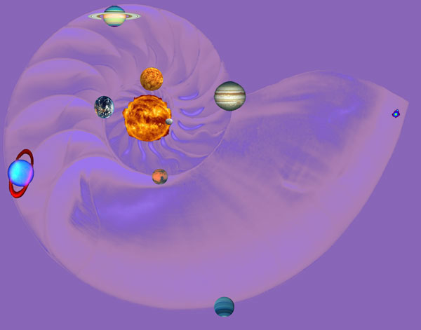
    It occurs to me that a coil designed like a
    Nautilus shell (or other shell with golden section ratios),
    might be interesting.
    The "physic intuitive" discussed how the red people,
    which had reached a very high level of technology in the
    ancient past succeeded with their technologies by
    copying nature.
    They would build machines that operated in ways
    similar to the ways they observed plants, animals and the elements
    behaving.

    Tribolumineseense, for example, was discovered
    and utilized to make free energy lighting devices
    by the Ute Indians.

    Triboluminescence - Wikipedia, the free encyclopedia

    The cosmos is a coil, within a coil, within a coil.

    Why not build a gradually increasing radius coil that
    spirals around itself, creating a coil within a coil?


    Last edited by morpher44; 08-15-2009, 05:55 AM.

    Leave a comment:

Working...
X