Announcement

Collapse
No announcement yet.

The Mechanical Engine

Collapse
X
 
  • Filter
  • Time
  • Show
Clear All
new posts

  • Vortex
    replied
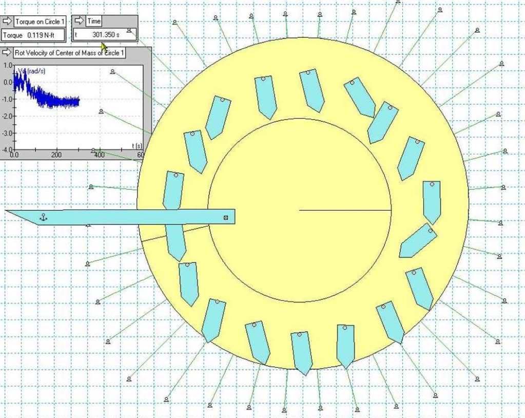
    Well, it's not a fluke, I've created 4 running devices ..
    but that depends upon your definition of running?
    I think the software I'm using is broken.
    It generally stops processing if I try to monitor things.

    All of my devices are unbalanced but not by design.
    They are Chaos devices by design.

    I'm using rubber and steel to get some extra kick out of the movements.
    Steel on steel is too much kick.

    I didn't know what I was doing when I started, so all these except the last one are very large devices..
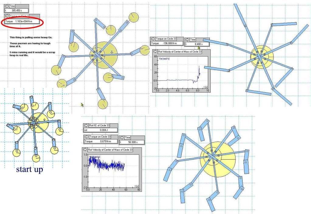
    1st device, WildOne, has 8 - 2 meter length pendulums on 5.5 meter across arms, takes 192 frames before it takes off into hyper space. The software is screwed up?
    This device runs not in one direction but both., back and forth.

    The 2nd devise, Wiggler, is a 8 double-pendulums on 5.5 meter across arms. Both parts of the double-pendulum is just over a meter each. This one just wiggles back and forth mostly and at 900 seconds it's still wiggling like at the start.

    The 3rd device, PacMan, has 8 double-pendulums on 5.5 meter across arms.
    First section of pendulum is one meter and second is 0.39 meter circle.
    This one works like the Wiggler but blasts off into space.

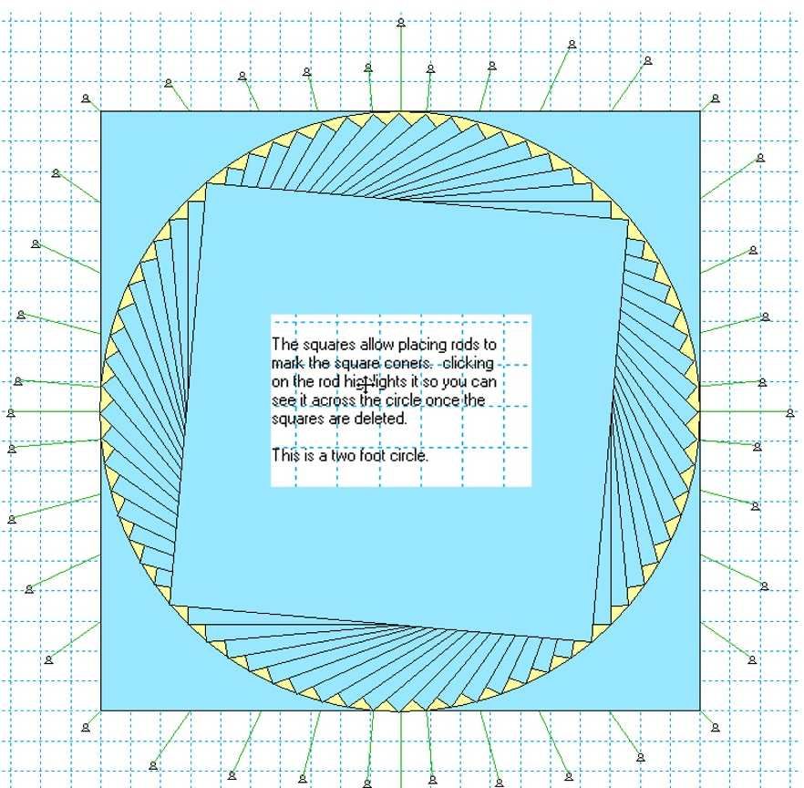
    The 4th one is a copy of Inquorate's mounted on a two foot rotor.
    Hey, a small device
    I couldn't get the device to rotate with a slow down bar installed.
    Very slow rotation.
    This is the only device that rotates only in one direction, once it gets going.
    Since it is so hard to create these devices with this software I used
    no collision on the pendulums so I could get the number of pendulums
    on the devices without having to rebuild the deive.

    The WildOne and PacMan in the virtual world hang together, but in the real world they would fall apart from the forces. that must be why the software keeps stopping.

    Would been nice to try these designs on some other software and see what comes of that.


    Data files for these devices are in a zip file at this link:
    RapidShare: Easy Filehosting
    Working Model 2D required, if you don't have to software don't download the file.
    There are will only be 10 downloads of this zip file allowed by rapidshare.


    Randy

    Leave a comment:


  • Mark
    replied
    Michael, at the bottom of the first page after you go to renewable energy there will be a "NEW THREAD" button just like the reply button you hit to post.

    Leave a comment:


  • Michael John Nunnerley
    replied
    Peter, how do you start a new thread

    Mike

    Leave a comment:


  • Inquorate
    replied
    Sketch

    Gravity+mill+sketch.jpg (image)

    I'll use a wheelbarrow wheel axle and bearings for the centre, planks for the arms, skateboard bearings for the pendulum axles with 1/4 inch bolts thru them.

    Excersize weights for 'flywheel' etc. Wheels on the ends of the pendulums?

    Eccentric wheel will be adjustable on the main axle.

    Damping bar has to be more adjustable, another bar it can be moved left and right on?

    And a bicycle pedal cog for chain to small generator.

    And about half the size indicated, so I can work on it in my loungeroom. Oh and 8 arms, not 4 - was keeping sketch simple.

    Love and light.

    Edit; my wm2d file is 17mb if anyone wants it; also I have Woopy's many pendulum large eccentric wheel version's file, about 2 megs. I guess springs take up lots of memory in a save file..
    Last edited by Inquorate; 03-25-2009, 11:57 AM.

    Leave a comment:


  • Inquorate
    replied
    Sucahyo

    Been on worker's compensation last three weeks, so seriously limited funds and haven't built one yet. I'll upload a sketch of my design and what it'll be made of and how..

    Leave a comment:


  • sucahyo
    replied
    @Inquorate, nice work . What thing you used for damper in real prototype? cloth or sponge?

    Did you use nut & bolt for pendulum weight?

    Leave a comment:


  • CloudSeeder
    replied
    @ inquorate: well, no they wouldn't because on the Up side the smaller weight would be going up first. However, I do not think that to be a terribly crippling problem because exact mirror image on each side is not the relevance you think. What is relevant is that at any given moment the total right HALF be close to same as the total left HALF. It could just turn out that not being exact mirror image could work IN YOUR FAVOR.

    Remember too that when the device is in motion a certain amount of slight indifference doesn't mean the same thing it means sitting still... much like Dr. Lindemann has previously pointed out about needing to run faster when not under load so it can bear the load of a generator when added.

    Until that time it's impossible to know whether the indifference works against or for the device. In my opinion it is somewhat likely to work against the motion at slower speeds but reach a pinnacle, a breakover like an ocean wave breaking, a sweet spot where it switches to working for the device. That will be the speed it runs at under load. The generator size would have to be adjusted to the correct for that point, or even possibly a small "window" of points.

    You do good work.
    Last edited by CloudSeeder; 03-25-2009, 06:22 AM.

    Leave a comment:


  • Dingus
    replied
    I've just about given up on my attempt at testing the mechanical engine by making laser-cut parts.

    Sadly enough, this isn't due to mechanical failure, but my inability to make a decent template.

    In other news, I got my hands on a rather large (free) sawblade that might make for a nice ratchet for a woopy-style gravity mill.

    Leave a comment:


  • Inquorate
    replied
    @ cloudseeder - that idea may have merit, so long as each weight's opposing weight is the same..

    Leave a comment:


  • CloudSeeder
    replied
    Perhaps the swinging pendulums would benefit not all being identical weight. Make them in sets of 3 => lighter, medium, heaviest. Perhaps the 1 then the 2nd and then the 3rd would add into an increasingly-powerful harmonic pump. The 3rd one being the heaviest would pull the next set of 3 forward with a bit more OOMPH.

    Leave a comment:


  • Peter Lindemann
    replied
    No Offense Intended

    Originally posted by Inquorate View Post
    We also call a petrol engine a petrol engine, not an internal combustion engine as it should be called.

    @ peter, I just realised from your wording in your above post '' issue may not be cleared up until someone actually builds your design and tests it on the bench''

    That you are implying that the difference between my software simulation and yours is that mine is yet to be tested on the bench...
    Inquorate,

    I am intrigued by your design. I am excited that the simulators have indicated the design works. I look forward to you and Woopy continuing to post in this thread on these developments. From all of this, there seems to be every reason to move the project forward to "working models". I look forward to the possible success of these physical prototypes.

    In contrast to this, my design is speculative based on DOZENS of test models and 5 years of thought. It has not been simulated (that I know of) or reduced to practice (that I know of). Along with the discovery of the piano movement in the same time frame as Bessler's discovery, it seemed worth publishing.

    But you and I are not in a competition. The purpose of this thread is to promote the idea of a truly "mechanical engine" based on the action of swinging pendulums.

    My article was written more than two years ago and was gathering dust in my computer, so I published it. "Your solution" is remarkable and simple, but it is based on the ideas in my published article. But that was the point of publishing.

    I am not criticizing YOU. I am "concerned" about the issues I have raised with regard to your design and its "function" in the simulator. There are a number of things that seem "counter-intuitive" about the simulator results. That does not mean they are wrong, just deserving of careful observation.

    Please do not take offense at anything I have said in this thread. I have made no personal comments about you, and I never will.

    I HOPE your design works and that an insanely simply energy machine can be made from it to turn a small generator in my garage! Nothing would make me happier!

    Peter

    Leave a comment:


  • Inquorate
    replied
    2 more cents

    We also call a petrol engine a petrol engine, not an internal combustion engine as it should be called.

    @ peter, I just realised from your wording in your above post '' issue may not be cleared up until someone actually builds your design and tests it on the bench''

    That you are implying that the difference between my software simulation and yours is that mine is yet to be tested on the bench...

    Leave a comment:


  • Inquorate
    replied
    a rose by any other name

    I'm calling it a gravity mill because while one side causes downward force due to centrifugal force from swinging pendulum, gravity is tricked into giving us that swing.

    without gravity it would not work. I do get your point though; we don't call a windmill an air pressure differential engine.

    Woopy, you're going to need much more pendulums. Try using the program to make the wheel on your bench, ratio / weight etc..

    I think also it won't move.

    @peter

    'Chaos engine' maybe? :-D

    I'm drawing up plans for a 2m (1m beam) version, see if she'll dance.

    Leave a comment:


  • woopy
    replied
    the reality is speaking

    Hello all

    today is not so good

    I spend some hours in the workshop to do real Besslerratchet proto

    and until now i got no succes

    i enclose here under some pictures of the real set up

    the main wheel is very loose i desassembled all bearing and clean them perfectly then i remount them and add fine oil and got a very loose system .
    I tested different weight of pendulums
    the ratchet tested with a saw disk with very fine teeth spacing and as you can see the center hole is wide enough that i can trim the eccentricity of the ratchet at will than as Peter Lindemann suggested i tried a partial ratchet and let the pendulum "cliff-falling" but i noticed no pendulum acceleration downway

    than i tried to initiate and increase the Milkovic-to- ratchet efficiency with springs but until now no succes

    but the good thing for today is that i have a bench and a wheel and ratchet and pendulum that i can move with my fingers and get the real feeling and i hope that i will find the key to make this accelerate

    all the best

    waiting comments

    good night

    Laurent
    Attached Files
    Last edited by woopy; 08-13-2010, 10:04 PM.

    Leave a comment:


  • Peter Lindemann
    replied
    Questions and Concerns

    Inquorate,

    This design is, indeed, interesting, but I am concerned about a number of its features. The primary thing that bothers me is its RANDOM functions. Success seems dependent on a certain amount of CHAOS in the movements. Every time these parameters are tightened up in the simulation, the machine stops working.

    In science, there are no operating engines that depend on chaos. Without exception, every motion is tightly defined and regulated to produce the end result of energy production.

    This ISSUE may not be cleared up until someone actually builds your design and tests it on the bench. This will teach us something about both the design and the viability of the simulation.

    I am also curious why you are calling it a "gravity mill" when clearly, gravity is not driving the system. The design only "works" in the simulator if the weights "swing" more on the right than on the left. This strongly indicates that the driving force is the centrifugal force generated by the pendulums in the vertical plane. Would you be willing to discuss your reasoning on this issue?

    Peter

    Leave a comment:

Working...
X