Photos to go with last post
Dear Researchers,
Here are some photos to go with yesterdays commentary.
The photos names pretty well describe what they are.
Mark McKay
-
Evaluating the Stored Energy in Gray Circuits
Dear Hard Working Explores of the Unknown,
The attached schematic is a proposed method to see just how much energy, classical and non-classical, is stored in the capacitors of the Cole/Hackenberger Free Energy topologies.
Since the original technology is documented to have achieved a COP of 275, then we should be able to see at least COP's greater than 2.0 with this approach. If COP's less than this are observed then we probably have not found the anomalous mode of operation.
The theory of operation is simple. Place two coils on top of each other and allow the energy from our storage element(s) under test to rush through them. The total real energy absorbed by the moving coil will be its height x weight x a conversion factor (which is about 0.76 - but I have to look it up again). Accuracy is a real issue here. What finally gets converted into momentum is less than what is actually stored in the capacitor(s). They are:
DC resistance loss in the coils and connecting wires - about 2K Ohms here
Friction losses as the coil moves up the guide rod
Air friction losses
Eddy current losses
Coil parasitic capacitance losses
Switching losses
And probably about 10 more that I haven't mentioned (or even know of)
Therefore we have to have more energy in the capacitor to cover the many losses in this approach in order to see any movement at all.
For classical Mass Drivers the conversion efficiency is about 6%, so we are going to have to take any data derived from this approach with a huge dose of salt. The main advantage is that the method is inexpensive to implement. The next step would be a $20K Tektronix Power Analyzer.
There is a good chance that the particles I'm looking for can't even be observed with voltage measurements. We know that Gray and company harvested their anomalous energy with opposing coils - so we may as well follow suit.
This proposed circuit is just the beginning of a series of experiments. The next phase is to see how much energy is stored in both capacitors. Next is to introduce a switching gap between the stationary and popping coil - so that as they separated the circuit would be broken (stretched Arc concept). After that is the employment of a shunt diode - like what is shown in the CSET patent. Indeed there are several variations to examine, along with all the changes in the FFF that can be done.
I shall have photos later. This setup is almost all built using coils salvaged from a couple of clock motors. I just hope there is enough energy to make my coils move. At least I have 3 Joules to work with right now - but will that move the coils with all the losses discussed?
Stay tuned...
Mark McKayLeave a comment:
-
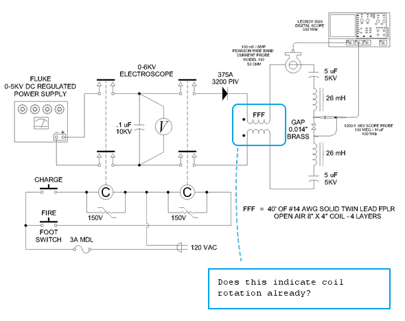
 Guest repliedDoes the electromagnetic orientation of the bifilar coil depend on whether
one winding is made at the same time as the other instead of being
separated in layers with the second wound around the first?
When they are both oriented in the same clockwise rotation, does it
generate a different electrical effect than having the first clockwise and
the one around it in reverse clockwise?
Leave a comment:
-
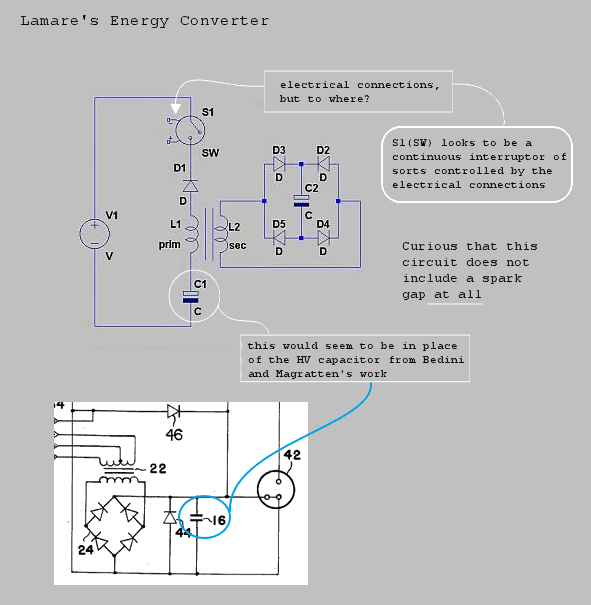
Guest repliedenergy conversion
The following diagram is shown with markup pertaining to the
concepts of its operation, for which hopefully someone would
be so kind as to explain... Also helpful would be a working
video showing the values of energy conversion through the system.
The source of voltage appears to be a standard battery.
Thank you lamare for sharing this earlier -
Leave a comment:
-
Forum strangers :: Topic: Literature (1/4)Originally posted by Spokane1 View Post
I placed it there for you!
Look at my last note on the site
Forum strangers :: Topic: Theory (5/37)Last edited by lvleon; 07-27-2013, 02:59 AM.Leave a comment:
-
Scope Traces
Dear Nat,Originally posted by nat1971a View Post
Scope traces are like looking at Chinese writing - if you don't know the language one is hopelessly lost. In this case if you don't know all the instrumentation connections, settings, circuit details, etc. the information is almost meaningless. Too bad there wasn't a better way of communicating complex data like this quickly (especially if we are looking at noise garbage) - but this is what we have to work with. Fortunately, this observation is not important (at the moment) and was just something novel to wonder about (as if we don't have enough of that already). If I come across something really important I shall take serious measures to attempt to communicate it in detail fullness.
Attached is a modified schematic from the Gray Pulse Engine Patent that shows the speculative thoughts behind this exploration into Tesla Equi-Drive circuits.
Mark McKayLeave a comment:
-
From single pulses to continuous operation
Fellow Researchers,
I have been exploring the impact of single pulses on a simple Tesla Equi-Drive spark gap, however I have run into a limit as to how far this approach can be taken.
The idea was to charge a capacitor then discharge it through the series circuit of components to observe what it does. The next step was to reduce the size of the capacitor, and therefore the total energy per pulse down to a level that would resemble the multiple pulses that would take place in a continuous system. I started with 5 uF, then 1 uF, then .5 uF, then .5 uF and finally .1 uF. This is far as I could go even though I had several other HV capacitors lined up that went all the way down to 50 pF.
At .1 uF there is not enough energy left to reliably strike the arc, even though the gap voltage measures out to be plenty strong enough. The charge just sits there for a good 400 microseconds before a breakdown occurs.
I guess (which is about all we can do with an unknown technology) that there is a lot of energy overhead needed just to charge up this circuit before it will fire regularly. There is parasitic capacitance in the field coils, the hookup wires, and the diode. All of these must be topped off before the energy will spill over into the gap. This makes observations with single low energy pulses a marginal exercise.
How large were the pulses that were employed in the Gray technology? We can get a ball park figure from a few observations from the EMA4-E1 Free Energy Engine. It is strongly believed that this machine employed 18 each mechanical automotive vibrators/choppers (instead of transistors) to excite the voltage step-up transformers (or induction coils). Now these devices are rated at about 30 Watts and run at 100 Hz. Using napkin calculations this would be 30 Joules per second or 300 mJ per pulse. This would be the upper limit. I suppose about half that figure would be more like it.... say 150 mJ.
Now my .1 uF capacitor charged to 3060 volts would contain (in an ideal world) about 468 mJ. So, for a single pulse it takes about three times the energy to shake out all of the slack in the system in order for an individual spark to strike.
So, I have moved up to a continuous system. I have acquired, from my favorite surplus store in Portland, OR, an old 12DC to 5000VAC inverter. I have no idea what this was used for but it is built around what looks to be a Neon Sign Transformer. It has a simple two transistor chopper that employs Germanium, PNP transistors. I'm sure it is current limited like most NST's. The rated output current is 19 mA. The primary fuse is 8 Amps MDL.
This is a heck of a lot closer to what Richard Hackenberger was using, however he had dual outputs for some unknown reason.
Preliminary Smoke Tests. (Less the FFF) using a 25 Ahr wet cell storage battery
- The open circuit voltage output is 5.5 KV (The electroscope measures AC and DC on the same analog scale)
- As the circuit is loaded with the Tesla Equi-Drive components the output voltage drops- due to the current limiting design
- The output (whatever it is) will jump a 0.075" gap (five times longer than what I could get a single pulse to do)
- The Tesla Equi-Drive capacitors (5 uF) quickly charge up to a steady voltage and stay there. In this preliminary observation this value was 1100 VDC. What is odd it that this build-up does not inhibit the continuous arc like it does in single arc experiments. In all of my computer simulations as long as the arc is working (current flowing) the charge on both capacitors should continue to increase until it reaches the magnitude of the supply voltage. Something is very odd here that I need to understand.
I haven't connected my scope voltage probe to the setup yet until I'm sure I will not blow out my front end. An isolated pulse is one thing, 5500 VAC continuous is another.
I may not even use the oscilloscope. My current probes seems to give me garbage readings when working with these kinds of currents and I'm afraid to use the high voltage probe since there is a high probability that any ground connection will destroy the phenomena I'm looking for. The solution is to go for the gusto and cut to the chase by measuring the effective repulsion energy directly by means of some small "popping coils". The height/weight of a moving coil gives a direct reading of harvested energy. All changes and modifications will be evaluated in terms of effective energy yield.
More detailed voltage and current wave forms will have to wait until I bone up on how to take HV measurements on isolated/floating circuits with an Oscilloscope.
Next step, finish off the popping coil device.
If anyone is interested in this line of exploration I would be glad to post photos of the preliminary setup and of the internals of the antique DC inverter. I have also developed a proposed schematic of the inverter but I haven't drafted it yet.
Mark McKayLeave a comment:
-
Improved Arc Link
Dear viruskiller,Originally posted by viruskiller View Post
Thank you for providing this link on potential useful ancillary technology. However it is completly blocked by the company computer. It will take me a little time to check it out.
Mark McKayLeave a comment:
-
What do you think of this idea.
What do you think of this idea
See the link below.
Improved Spark Gap and Possibly Free Energy(Eclateur Ameliore Avec Possibilite d'Extraction d'Energie Du Vide) Doc in English and FrenchLeave a comment:
-
Mark,
That is a very impressive setup. Looks like you have spent a lot of time putting this all together. Hopefully soon we will have the break through that the world needs.
Thanks for posting yours photos.
Not sure what to make of your scope traces. I have been wondering whether Gray/Cole accidently discovered something when the FFF was wound on the outside of the motor casing. Wireless transmission perhaps. Seems an odd thing to do to me. Mind you i do recall Tesla having something similar in 1896/1897
Cheers
NatLeave a comment:
-
Additional Photos
Dear Nat,Originally posted by nat1971a View Post
Here are some detail phoots of the components and equipment used.
- 100 Amp Contactor: This is shown with the cover off. I like to see what is going on with the arcs. This is the larger of two contactors used. Both have 120VAC operator coils and are operated with a foot switch. The coils are supressed with 150V Varistors. The Scotch Tape is for size reference.
- 375 amp diode - This is a module composed of two diodes in series. Individually they are rated at 1600 PIV at 375 Amps. This unit cost $10 at my favorate surplus store in Portland, OR. I supose its shut off time is slow, but I haven't measured it.
- Twin Lead FFF - this is just a WAG as to how the real FFF's were constructed. It appears that Mr. Cole used Coax. In this case I wanted a delay line long enough so that I could see something happen. I plan to go back to coax in the future.
- Spark Gap - The addition of the inductors is a WAG of the week. If you analyze the Pulse Engine Patent mechanical drawings you will notice that there are two modes of operation. I suspect that one mode was used for energy generation and the other was for the utlization of the non-classical particles. In the power generation mode (which is a guess on my part) the two Major electromagnets are directly opposed to each other. This is not a position that generates torque - so it might be part of the non-classical generation process. In this setup the arc is part of the cores of the coils as I have observed in the Gray "popping Coil" demonstrations. The coils are connected so that they attract. This is intended to provide a uniform magnetic field for the arc to develop in. The brass screw heads being used for the arc electrodes is rather lame - but the threads were already in the cores. The cores are 3/4" in diameter and 1" long. They are solid soft iron cylinders the cunduct the current. These coils came from an old copy machine and seems to be sort of what I needed for this intitial experiment. The actual space between the brass screw heads is 0.014"
- Setup less FFF - This is what the setup looks like with the FF removed. The smaller contactor can be seen at the left. For this shot I had the gap shorted to see if the residual "Hash" would go away - it didn't, which points to the remaining hash as possiably coming form the contactor. A good reason to upgrade to SCR switching.
Mark McKayLeave a comment:
-
Promised Photos
Dear Nat,Originally posted by nat1971a View Post
OK here are the photos of the present round of experiments. First off is a series of Scope Traces to show the opserved impact of the FFF in this Tesla Equi-Drive layout. All of these presented traces are taken from the Perason Model 110 Wide Band Current Transformer, so they are suppose to be current measurements. The peak current is 2.35 Amps, that 46 mH of series inductance sure cuts down the current flow. All of these traces are done with single pulses ("shots").
D005 - This is what I have observed in my setup using the larger contactors. One is used to charge the storage capacitor the other is used to "Fire" the capacitor. This allows for complete isolation of the discharging capacitor. In this experiment I'm using a .25 uF capacitor. Notice all the "Hash" as the current rises. Now these numerous pulses riding on my current wave form can't be classical current. Something else is going on. The current can't change that fast with that much series inductance. The probe is picking up something else - and I dont know what it is or how it gets there. But they are repeatable and consistant from shot to shot. What is interesting is that they only take place while the current across the spark gap is rising.
D006 - By decreasing the time scale t0 5 us/div we can see that this "Hash" is composed of individual bursts that last about 3-4 uS.
D007 - Decreasing the time scale to 1 us/div we can see the peak magnitude of the initial components of the burst. It is about 1.6 Amps if it were really a current measurement.
D008 - Decreasing the time scale to 20 nano-seconds we can see the structure of the burst packet. It is composed of 4 frequencies that each turn on an off in their own order. This is not a linear response so part of the source of this observation must come form some interaction with the spark - unless I'm looking at some kind of instrument artifact.
D009 - This is the clincher. This trace is with the FFF removed. Notice that the "Hash" is gone. All the other components are the same and still in the circuit. This implies that the the FFF is the source to the "Hash". Actually I think it is its interaction with the arc and all the other components in this proposed setup. Again I still could be looking at some kind of instrument artifact or other distracting interferance.
The photo is the present setup with the older and smaller contactor. I shall post another message with additional detail photos.
Mark McKayLeave a comment:
-
Old Coax FFF Setup
Dear nat,Originally posted by nat1971a View Post
Here are some photos of an old (2008) attempt at generating "radiant energy" using a coax FFF (RG59) with a conductive coil form and a chopper power supply suggested by the Gray Pulse Engine patent.
I'm using a ignition coil for the step-up transformer with transistor choppers. The aim of this experiment was to charge the 40 uF capacitor bank to 3KV and see how high the popping green coils on the right would go (they jumped about 45"). Then charge the capacitor bank directly from the 5KV Fluke power supply in the back. Then compare the differance.
In this attempt there was no differance in the height obtained from the Gray power supply or the Classical Power Supply. Obvisouly I hadn't hit upon the "Trick" in this round.
Best of luck in working with FFF's with conductive coil forms. I certainly didn't do an exhaustive exploration of this approach.
Mark McKayLeave a comment:
-
wow!!! thats some professional setup you have there...can't wait to see the photos...well doneLeave a comment:
Leave a comment: