
would love that video translated.
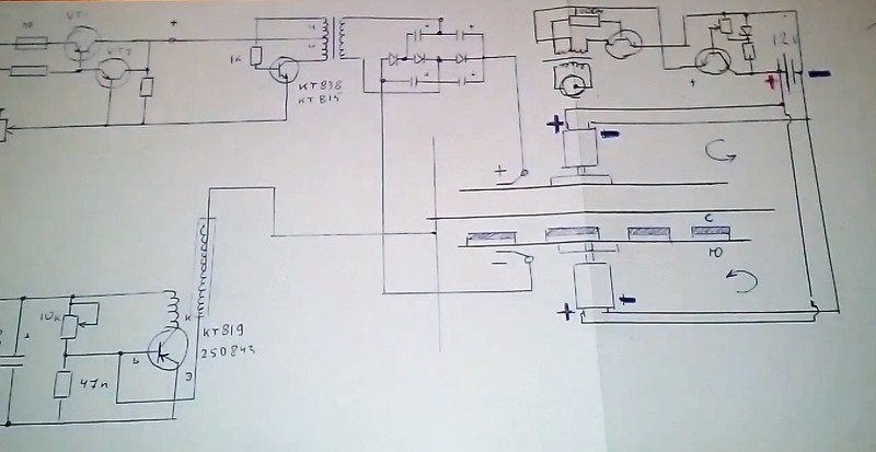
anyone know what the upper right part of the schematic is doing ?
the item connected to the transformer is what ?
-----------------------------
I am pretty sure the low RPM is so the magnets don't fly off or cause to much vibration.
----------------------------
"As for the Tesla COIL...do you think a 12V ignition coil would do?"
it would seem that he set it all up to balance perfect,
if you had it set up with variable output it should work
-
Hi Sputins,Originally posted by Sputins View Post
Well I believe you all know where am starting right?
Yeah, building the small UFO first...
I will let all the electronic engineers do the components research and finds...of the more suitable parts available.
I believe the distance between all 3 discs is so open to avoid discharge sparks between them.
In another video with the "Katcher" or Tesla Coil he shows the length of the arcing spark, guess that gives him an approximated gap distance to set all 3 discs...but like you've said, with adjusting threaded rods we could set them right.
Good detail you've catched with isolating motors shaft from spinning discs...yeah we don't want HV DC to enter motors.
I also see all discs made of aluminum...I have a few cuts laying around from another project about similar size.
Why Six magnets?...well guess he likes that number...it is within the famous 3,6,9...
I guess -seriously now- that is the best choice because of symmetry and minimal weight...while keeping a pretty closed arrangement...2, 3, 4, 5 are too spaced apart then less stable for low speed RPM'S.
Did you notice magnets have a hole in center to screw to disc....neodymiums...all oriented same polarity up-down (notice shaded half on diagram above)
As for the Tesla COIL...do you think a 12V ignition coil would do?
My weakest point in understanding of whole thing is what you are explaining above...the DC HV -/+ to the two spinning discs...circuit...he does say about a "voltage multiplier"
Yeah...a sequence...I see he first turn on motors on all tests...but then which HV second and which third on sequence?
But like you said...let's make all parameters adjustable first...is the way finding the sweet spots (all).
Regards
UfopoliticsLeave a comment:
-
Yes - thats true!Originally posted by Ufopolitics View Post
I'm sure there are a few readers scrambling to collect the parts right away...
Most of this is device is within the scope of ability for most people on the forum I recon.
More notes, observations & questions:
It looks like the HV DC is made from a centre tapped transformer in reverse, used as a step up transformer, because he's running it from a 12v battery, chopped by push-pull Mosfets. So it probably steps it up to at least 240V AC and then rectifies it. Somewhere it says he uses a voltage multiplier on it too. So at least 340V DC, probably more like 1kV to 30kV?
The motor shafts are electrically isolated from the discs. - Seen pictures to indicate they have plastic hubs which attach to the shafts.
Notice there is no HV spark arcing or discharge on the brushes... So the HV DC plus and minus charge contacts the discs, but there is no directly completed circuit as such. - It is a field interaction or charge factor...
Rotation of the discs seems pretty slow... There are smaller & way faster RPM motors available and are quite cheap. - But perhaps a slow-ish rotation is better for some reason? A variable speed control here is likely best?
The large centre plate, with no holes in it, seems to feature in each design, so it must play an important role. It looks like its aluminum? So perhaps a "non magnetic" conducting metal is necessary?
What is the frequency of the Tesla coil? Is it important?
There is likely a sweet spot for the distance or proximity of the rotor discs. Much like a Bedini motor, it is probably critical to get it spot on? He uses threaded shaft supports which means they are used to move them to the correct positions before they're locked.
Why six magnets? Why not eight or twenty four magnets? Does it even matter?
It is mentioned that there is a certain sequence to follow as well.
Lots of variables... Time to sleep on it.
Leave a comment:
-
Hi Sputins,
Just love your brief analysis above...and of course I agree and believe is the closest approach to understanding what's going on here without any sophisticated wordings plus invented lexics.
I believe so...I believe all components at work -on device- contribute to the generation of some kind of "gravitational bubble" surrounding the Apparatus. So once this ANTIGRAVITY force (ANTIGRAVITY or counter gravity vectors of force) reaches a point, which is just a bit greater than the weight gravitational pull of the whole thing...then, of course it will ascend.
As he also mentions...The HV is the final ingredient for lift up.
I believe the spinning discs plus the central disc HV generate the basic bubble which the spinning configures in a counter VORTEX pattern.
IMHO and in other words, this is basically a Huge Plate HV Capacitor with the DYNAMICS to stir the outer plates electric fields... and a "ring" of magnetic field which creates a hollow spinning magnetic field...leading the electric field into a VORTEX as well.
But then again...this are just Theories...which means nothing until proven right...
Only reality is to build it and prove it works even if lifting up only one inch above ground level...as I believe the lighter it would be the lesser HV would be required just to demonstrate it works.
Regards
UfopoliticsLast edited by Ufopolitics; 09-13-2018, 02:48 PM.Leave a comment:
-
You have no idea...how long I have been working on this same project.
Hello,
This has been my dream for many, many years back...actually the ASYMMETRICAL motors came up from a patent granted 18 years ago...
In that patent I have a completely different motor structure known so far...to the point patent was issued.
On the simplest form, in order to put it briefly, just one stator could spin at least two rotors...counter or both same direction...just a matter on changing terminals or inverting up/down positioning on one rotor...
But MAIN aspect is that NONE of these assemblies have a center shaft.

Imagine a motor without a shaft?...well...what is it good for Sir?...where do we add/show/insert... the "take off force" from?
We could spin these two rotors COUNTER DIRECTIONS at super high RPM'S...and still center Stator will remain very calm and stable...
Its main purpose was to cancel gravitational forces...with great stability, plus a model that could be expanded to any desired size...and still having a hollow center...meaning, scaling it up will not increase weight of the whole assy.
But I completely abandoned this project and spent the time searching for free energy up to now...
I have been working on this devices ever since...but now I see the whole full 3D color movie...
Regards
UfopoliticsLast edited by Ufopolitics; 09-13-2018, 01:52 PM.Leave a comment:
-
We could start adding Theories as long as paper takes it...
Hello All,
@Sputins: I agree with your reasoning 100%...it seems so, this device even built so basically, it gives the primitive foundation for a Tech that could be improved/developed for better performance, and this ONLY will take place by lots of experimenting.
And I mean we could start theorizing for as much as A piece of paper will take...or this screen would accept...but DEFINITIVELY, NO THEORY would help us to achieve higher stages of development in reality.
@Skywatcher: I also agree with your views...
If you all noticed...on his first prototype both spinning discs have magnets...
On the second one, the one which levitates inside his house PLUS Outdoors...ONLY have magnets on lower spinning disc.
Concluding that He keeps testing and removing unnecessary components and still achieve success...This will lead to more optimized prototypes.
I believe the high delay to take off is just due to the same issue...or a need to develop further and further...maybe Higher HV...maybe Higher RPM'S...maybe less...I don't know...do you?
We will ONLY get our answers RIGHT on BUILDING AND TESTING.
I believe this is real...I have observed each detail when lifting...all the inertial turns due to motors spin...the weight lift...the hovering instability which is not perfect yet, short up and downs but still keeping up at same height...the no presence of wind in outdoor takes...the construction, the details about the diagrams...the different prototypes attempts...etc,etc...
The Guy just hit the sweet spot and now we have an actual device, heavier than the air...which could lift off ground without any wind force propelling mechanism...
A VTOL (Vertical Take Off Landing) GRAVITATIONAL DEVICE which does not use any of the conventional means known so far, or "officially" recognized by Science...
We should start analyzing his circuit diagrams in depth...basically the two discs HV- DC voltage divider...plus all his field instruments then searching outputs...in order that Replications would be AS CLOSE AS POSSIBLE.
REPLICATING Without ANY RADICAL IMPROVEMENTS at this time...it is TOO DARN EARLY TO DO SO!!
Regards
UfopoliticsLast edited by Ufopolitics; 09-13-2018, 12:55 PM.Leave a comment:
-
Yes, I'm in agreement with both/all of the above. The machine is fitting the folk lore descriptions. I'm just trying to put a sensible face to it any way I can.
Wheeler does show in his first video that an accelerated magnetic field causes an expansion of the dielectric plane as shown in the attached video.
Now it is interesting to compare this to the ideas presented through Einsteinian Physics which John St. Clair is basically forced to use to explain his patents. Otherwise they wouldn't be approved obviously, and where in St. Clair talks about a slowed speed of light, but here in Ken's video the same explanation is factually demonstrated to be a slowed dielectric field.
Using Wheeler physics the demonstration shows that in truth the magnetic field is the dielectric field, and which is not really slowed light, but rather that the magnetic field is the resultant of a slowed dielectic field. This slowed dielectric field, when accelerated against surrounding space, induces a further expansion of the dielectric field. The way to greater dielectric expansion is to increasing impede the flow of the counterspacial dielectric field. Pushing a magnetic field around as fast as possible increasingly impedes the hyperspeed of the counterspacial dielectric plane as a kind of roadblock and leading then to greater manifestations of the same field: That's how I'm envisioning this system right now.
Now looking at this system we have essentially a kind of macro scale magnet. In other words it's like a kind of replication in giant scale of what one might envision how a magnet draws the dielectric field out of space, and just in order to become a magnet, and it is doing this by using motors and magnets like some sort of weaving machine to pull the dielectric out of it's hiding place in counter space. I have a sense that there is some time required before the lower and upper dielectric connect to form a complete dielectric field. Are you following how this works? That the lower and upper spinning plates are both playing a respective role of creating a field path in the dielectric plane to follow, and which will then, once connected above and below, be one and the same as that demonstrated by Wheeler as the dielectric field of a magnet. See how that works? It's like a weaving machine of sorts. We have in this design two motors turning two dielectric fields in opposition, but thanks to Wheeler we now know this is factually one directional flow of dielectric energies, and so if you look at this design as the very center guts of a magnet you've got the same thing as explained and demonstrated by Wheeler going on here.
I see similarities which also match the ideas presented in John St. Clair's patent, but without having to resort to the crazy insanity of insanely complex mathematics and also without the assorted convolutions which are required to explain antigravitational effects using Einsteinian Physics; where in St. Clair is forced to say an accelerated magnetic field, moving in a circular track, induces a slowing of light speed, which is somehow then proved by mathematical means, and after which then proceeds to explain how this all then results in an alteration of the physical plane of reality. The totality of which must require at least a major in undergraduate mathematics just to even know if the math is itself correct.
Whereas with Wheelers physics of the production of a magnetic field being the result of a slowed dielectric field, the demonstration more rationally and expediently shows that this same magnetic field, when accelerated in space, causes a further widening or expansion of the dielectric plane. This is a logical sensible outcome requiring no convoluted tortured path to comprehend. Aside from that Wheeler is validated by empirical evidence which is always more valid than theoretical fantasy. If the speed of light is slowed, as explained by St. Clair's patents, then it is slowed because it has a direct linked correlation to the dielectric plane.
[VIDEO]https://www.youtube.com/watch?v=VWMu0cndKl4[/VIDEO]Last edited by Gambeir; 09-13-2018, 08:48 AM.Leave a comment:
-
I have read Ken Wheeler's book and many of his posts.
it sure looks like he has seen something going on that is not standard physics.
but what he writes is just as bad as the theoretical physics people in that he never links things back to the physical world.
when I first asked him for definitions for the words he used, he acted like I was stupid. I would get that sort of reply if there was any sort of standard definition for the words on the net. but I had asked for his definition, and no non mocking reply was ever given.
he talks of vortexes, but not any of the details that would tell someone what he has seen, and I am looking for details. all the polarities, charge, and what it did to gravity...
would seem that all he offers is something that can be deciphered after someone else figured it all out on there own again.
years ago ken also said he was working with someone from india on this project (or am I confusing this with some remote viewing I did ?). so, I would like some product I can buy about now, so that I can figure out what the heck his theory was all about when linked back to the physical world.
but so far nothing.
just saying that pure theory where nearly every critical word has way to many definitions is not useful
even if you map it out, would take many lifetimes to build all the hardware to test all the ideas possible.
Ken may have a clear idea as to what is going on.
Just wish he would share it as opposed to making some giant puzzle that he gloats over no one else figuring out.Leave a comment:
-
You're right. There is a sense of this and as yet it is unclear. I have to think about it. You might be entirely right. This all might be associated with creating a dielectric bubble/balloon.Originally posted by SkyWatcher View Post
A dielectric field/flow, as demonstrated by Wheeler, creates the illusion of charges: An illusion of charges which technically are one and same energy explains without complexity why magnetism is an associated phenomena of electricity. Electricity itself being the resultant of one field of slowed energy passing through a form which interacts with it. A slowed energetic field is the dielectric field of counterspace which creates the magnetic field out of a counterspacial hyper velocity space by slowing it down. That suggests there an interior and exterior manifestation of the magnetic field is what we see as polarized fields, however the magnetic field is itself created from a sole point of origin. Orbiting as it were only in one direction.
Since the magnetic field is created by the slowing of this hyper velocity spacial field of dielectric energies, it follows that the creation of an electric current could not then represent the ultimate speed of light, and since light is itself then a product of a slowed energy. This alternate energy field must be moving at a higher velocity as presented in the theory of Superlight being a hyper velocity field of invisible/unknown/unrecognized energies which we can now be relatively sure is responsible for creating the magnetic field and which is a dielectric field.Last edited by Gambeir; 09-13-2018, 08:18 AM.Leave a comment:
-
Hi all, Hi gambier, very interesting stuff in this thread, thanks for sharing.
I keep hearing in my mind, 'Think Buoyancy'.
However it is doing it, if it is genuine, it probably is creating less density above it, than below it.
I notice it takes a bit of time to lift off, then creaps up when it does.
That seems like a field is being built up and when that field is built up enough, the density above and around the craft decreases and slowly pulls upward, just like would happen if we slowly injected air into a bladder under water.
An airplane wing needs a certain airspeed to decrease the density above the wing enough to cancel the weight of the entire plane, then the angle of attack is changed and the propulsion units accelerate climb.
Hydroplaning is similar, the water below the tire, becomes compressed, which means more dense than above and the tire can float across it at a certain threshold.
If what is called gravity is caused by density variances, then all these different levitation technologies, even though they may have different operating principles, are most likely still just creating a density variance above the craft for lift and a variance in front or back for forward or reverse propulsion.
peace love lightLeave a comment:
-
Good Job Sputins: One never knows the motivations of individuals, but if this turns out to be a fraud than we can at least make one more check mark off the idea's list, it won't be a total wash in that case. Also thanks for the screen shots as well: Those are helpful. I've got to send an email off to John Iwaszko about this whole thing and see what he thinks. If Ufopolitics or anyone else knows Ken and could do the same then we might have some other input which is also valued. I'd be especially interested in hearing what Ken Wheeler thinks, but also what you and everyone else thinks.
Keep in mind this is only like day two of even knowing about these video's, but off hand I have a sense there's likely something to this. I see a lot of tornado electrodynamics and Wheeler Physics whizzing about in this contraption. Keep in mind I haven't sat down and mapped this out with a pencil on paper nor had time to go over it even if I had. That method will show where unexplained and possibly fraudulent errors might lie. Nevertheless, lets take a quick once over on the design theory.
Analysis: Tornado Dynamics of charged electrical fields.
The machine is spinning two plates in opposition (A known proven method of weight reduction). These plates are also carrying with them the dielectric fields of counter~space formed by the magnets. The magnets dielectric fields act upon counter~space inside of our surrounding space, and to twist out of space a counter~spacial helix forming a dielectric river of condensed threads. To accomplish this and to assist this creative process the plates carry the negative charge field associated with counter~space. In reality though the negative field is counter~space.
Each plate carrying a negative charge field is moving in opposition. This is consistent with the outflow and inflow of a cycling dielectric field as outlined by Wheeler. In this case you then have a model of dielectric counter~spacial field flow of a magnetic field.
My understanding of what I think is happening is that our surrounding space is a positive charge field, and counter~space, for the dielectric field, is the negative space: I see this as a cycling from interior to exterior and thence back repeating this flow cycle. That is to say the idea of charge polarity is an illusion produced by the cycling of a dielectric plane coming out from a counter~spacial field.
The anterior force of space, or the positive field as we know it, is the apparent exterior field of the dielectric fields own cycling flow and passing to the outside where we recognize it as a positive charge field. The so~called positive charge field is more energetic because it's in our space naturally enough, and therefore it does contain as well as constricts rivers and threads of counter spacial dielectric matter, or what we recognize as the negative charge field: In truth though, as shown by Wheeler, this is a cycling field of energy flowing from one point out of counter~space an then again back in: It is one and same. However, with this understanding we can then explain affixing a negative charge polarity to the plates with the attached magnets, and whose own dielectric fields is then used to assist or coax out of the surrounding space a dielectric river of threads to form a helical dielectric field which is then pulled from the interior of our own surrounding spacial plane of reality.
With each helix going in two opposite directions we have the same pattern flow as demonstrated by Wheeler of the magnetic dielectric flux field. These now being more like rivers of dielectric space whipped in to a helix. In tornado dynamics these would form the interior tube of the twister which is a negative charge field, or the counter~spacial plane itself.
The positive polarity (such as we still call it) is a more energetic charge field, it's attracted to the so~called negative charge field because it's trying to absorb the dielectric counter~spacial reality back once more in to it's own self where it is positive that negative counter space should remain. The end product in a Tornado is a double sheathed tube of counter flowing charges. In other words a model of a magnet or the flow of spacial energy fields.
The pinched vertex lines of the tornado tube is the product of the spacial field being a positive charge field of space moving and pinching the counter~spacial field in a centripetal exterior vortex contraction, and which is induced by the mutual attraction of the spacial to reabsorb the conter~spacial negative plane; a spacial plane which originates on the surface of earth in this case.
*Now the HV should be transmitted by wireless. See the video I posted by John Iwaszko on wireless power transmission.
Can't help but recall that McCandlish said he thought the ring surrounding the crew compartment was an antenna.Last edited by Gambeir; 09-12-2018, 10:26 PM.Leave a comment:
-
But pressing ahead, on the hope that it's real...
So far I have seen three versions of these Discs...
Prototype Version-1; Second Version-2; and from the latest video, Third Version-3
Version-1:
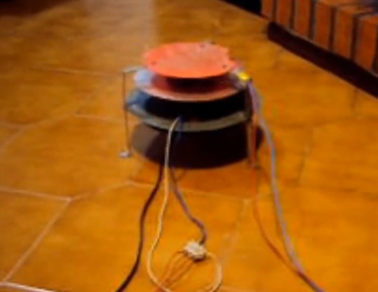
Version-1 Side shot:
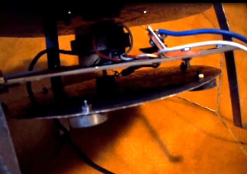
Version-2:
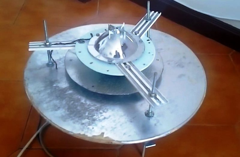
Version-2 Side shot:
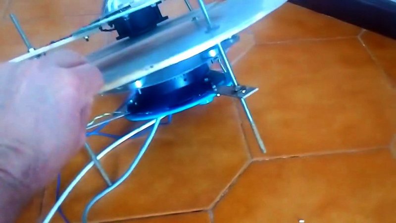
Version-3:
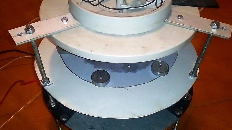
Version-3 side shot:
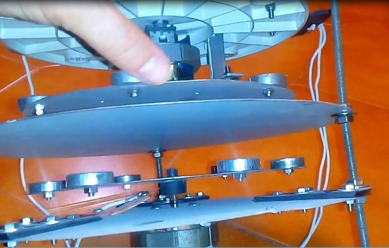
Circuit:
The circuit has Four parts.
1) There is the Disc assembly itself.
2) There is the Disc motor power supply
3) There is the disc DC high volatge power supply
4) There is the Tesla Coil and it's power supply
I am yet to understand fully how the disc HV DC power supply is connected to the spinning discs. I thought it was via a brush, like fine wire, but I can't see that... In the circuit diagram it shows the + / - HV terminal in proximity to the discs but not actually connected..?
Version 1 & 2 have the hammered finish aluminium plate, but the latest version-3, I can't see it there as yet.
The motors seem to have a fairly low rpm so the rotor speed may be a crittical element. Of course the voltages would be crittical as well.
Bed time.Leave a comment:
-
Is it real or hoax?
I hope its real.
A hoax? - One thing I noticed with the original version-1 prototype, from the first "Fireplace video", before it lifts off, there seems to be a cut in the video and then there is a shadow that appears just to the left of the disc. The shadow seems like it comes from Alex and it seems to move with the movement of the disc.. So from that, I can't say its a hoax, but it does present the possibiliy of one?
No Shadow:

Shadow:

Watch it again for yourselves...Last edited by Sputins; 09-12-2018, 02:59 PM.Leave a comment:
-
Hi Gambeir,Originally posted by Gambeir View Post
I like Carbon Fiber and Fiberglass for main frame...
As for the differential suggestion, I do not believe it will work for this particular design...unless we want to open a huge hole on center STATIC DISC, which I see it could cause problems that at this moment I cannot explain...besides, having just one HORIZONTAL Mounted motor will bring a lot of UNBALANCED results plus lack of stability when hovering by itself.
What's wrong with two small and cheap motors connected in parallel?...I see this as the easiest way to put it together. If you notice RPM'S are really low...so not even full blast of power is required...I would short cut on motor controllers by using two small brushed motors..
The Center Static Disc I believe must be BUILT AS IS SHOWN , meaning no holes in center plus way wider in Diameter than the spinning discs.
As for the HV supply delivering between 20-30 Kv...I believe a small ignition coil would do...as I believe it is positive HV (check the lamp attached to top of small Tesla COIL...it lights up when hand grounded.
Actually building the main frame plus motor-discs assy is the part would take a bit longer.
If you notice the lower spinning disc assy is off horizontal plane related to Center Static Disc...which means this technology is not as "picky" as RC Helicopters require a super precision plus accuracy...and that's an advantage for the builders.
EDIT 1: I almost forgot about the 2 phase PC FAN MOTORS!!...They should work beautifully for this device...as the do not require heavy torque here...since they are not propelling wind...but flat and smooth discs.-
Regards
UfopoliticsLast edited by Ufopolitics; 09-12-2018, 02:45 PM.Leave a comment:
Leave a comment: