
 Tweet
Tweet
Originally posted by Ufopolitics
View Post
-
Amazing circuit. +15 and -15 added together give 15. Wow!! Look at all the fantastic things you can do when education and common sense are thrown out the window. Simply amazing!!Just because someone disagrees with you does NOT make them your enemy. We can disagree without attacking someone. -
So, You add them up Really?Originally posted by citfta View Post
So, when we have the two Battery terminals -12V and +12V then we should have (according to you) 24V total ?!
Or...maybe zero, if we go by math signs?
You tell me (according to you) what result we should have there?Last edited by Ufopolitics; 07-29-2016, 09:18 PM.Principles for the Development of a Complete Mind: Study the science of art. Study the art of science. Develop your senses- especially learn how to see. Realize that everything connects to everything else.― Leonardo da VinciComment
-
So, let's forget about the Voltage Reg. transistors, Caps, and even from the neutral derivative at transformer...keeping it VERY simple (KISS).Originally posted by citfta View Post
[IMG] [/IMG]
Now, what should we have after the rectifier diode bridge DC OUTPUT "know it all"??!!
Isn't it +15.0V and -15.0 V at the Bulb terminals, minus any given resistance by diodes...which we could disregard for simplicity?
I would be waiting for your "genius" answer...Principles for the Development of a Complete Mind: Study the science of art. Study the art of science. Develop your senses- especially learn how to see. Realize that everything connects to everything else.― Leonardo da VinciComment
-
[QUOTE=Ufopolitics;290929][IMG]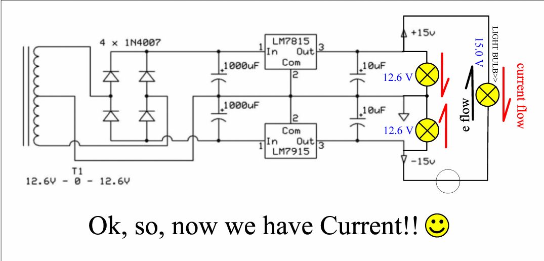 [/IMG]
For those of you confused by a dual voltage power supply I will try to explain it in simple terms. I have copied the schematic so it will be easier for you to follow. Let's start with the transformer. In this schematic we have a center tapped transformer that is labelled 12.6-0-12.6. The conventional way of marking a transformer is to use the RMS value for the voltage as that is what most AC meters will show when connected to the leads on the transformer. So from the top to the transformer to the center tap we have 12.6 volts RMS and from the bottom connection to the center tap we also have 12.6 volts RMS.
RMS stands for root means squared which is a way of calculating the average voltage of a sine wave. However the actual voltage peaks are 1.414 times the average or in this case 17.8164 which we will round off to 17.8 volts. Why is that important? If you look at the full wave bridge rectifier you will see that it is connected to the two outside legs of the transformer. So the bridge rectifier is rectifying about 35.6 volts minus about 1.4 volts for the drop across the diodes in the bridge.
What else do we see in the bridge circuit? We see that the center tap of the transformer is connected to ground and there are two capacitors that each have one end of them connected to ground. The ground connection is the little triangle at the end of the line away from the transformer. With the center tap connected to the capacitors and them connected to the bridge in this way each cap will then charge to close to the value of the peaks of the sine wave. So each cap will have a charge on it of close to 16 volts or so.
The designer of this circuit apparently wanted pretty good control of the voltages so he or she added a couple of voltage regulators for the plus and minus voltages to keep the voltages from going over the plus or minus 15 volts desired.
So for our output we now have a voltage that is plus 15 volts in reference to ground. And we have a voltage that is minus 15 volts in reference to ground.
And since one is 15 volts above ground and one is 15 volts below ground if we were to combine them we would have a 30 volt difference. So you can see the voltage values marked in blue are wrong.
While I am trying to educate a little those that would like to learn let's talk a little bit about current. In most of the old school discussions about electricity, electricity is often compared to water. And there are some pretty good analogies in that comparison. Most of you are probably familiar with the expression of gallons per minute. What does that tell us. Well we can be pretty sure that means some water is moving and the value of the gallons per minute tells us how much water is moving.
In electricity amperage means basically the same thing as gallons per minute means in water. Amperage is just a measure of how much electricity is moving. The word current just means there is some electricity moving. It means the same thing as flow means in water. If there is no flow there are no gallons per minute to measure. In electricity if there are no electrons moving there is no current to measure.
I sincerely hope this helps some of you.
CarrollJust because someone disagrees with you does NOT make them your enemy. We can disagree without attacking someone.Comment
-
Every time I look at that schematic it reminds me of the push pull EL84 amplifier, a wonderful piece of kit. hehehe If I remember correctly the outputs are added.

Comment
-
[QUOTE=citfta;290939]Thanks for the correction on Voltage split adding with center tap to ground.Originally posted by Ufopolitics View Post
I completely ignored the center tap, and thought of two terminals, pos and neg just like in a battery...my bad.
So, here is the corrected diagram for voltage output:
[IMG] [/IMG]
About current flow...is it correct?
The one I have confusion with, is the bottom 15V...where we have negative to ground, not sure if it will run that way...or if there would be power at all.
I do like that analogy to compare water flow with electricity...and the "gallons per minute" gives somehow a clear view of what current flow means.While I am trying to educate a little those that would like to learn let's talk a little bit about current. In most of the old school discussions about electricity, electricity is often compared to water. And there are some pretty good analogies in that comparison. Most of you are probably familiar with the expression of gallons per minute. What does that tell us. Well we can be pretty sure that means some water is moving and the value of the gallons per minute tells us how much water is moving.
In electricity amperage means basically the same thing as gallons per minute means in water. Amperage is just a measure of how much electricity is moving. The word current just means there is some electricity moving. It means the same thing as flow means in water. If there is no flow there are no gallons per minute to measure. In electricity if there are no electrons moving there is no current to measure.
However, I like to define current as "Electron Population" at a specific section of circuit, and of course by eliminating the time factor, we could conceive it standing still, at a paused time of a specific section, just because we all know it is there, just not "flowing" at a timed rate.
For example, going back to water flow...say we have two water gates (faucets) between a center conductor (pipe), and one is where the flow is sourcing, while the other is the drain or suction end...now at the source faucet we have the water pressurized, contained by being closed. Therefore, that water, pressurized at source gate means that by just opening it we will have a specific flow instantly running if the drain end would be opened.
From above water analogy, I believe we could be a bit more flexible whenever thinking of electrical current (not flow)...where at a specific closed point, we know we have that electron population and pressure to create an instant "avalanche" when we close or loop the circuit.
Must of us know that current defined by IThanks, indeed helped me on the center tap voltage understanding.I sincerely hope this helps some of you.
Carroll
UfopoliticsLast edited by Ufopolitics; 07-30-2016, 01:05 PM.Principles for the Development of a Complete Mind: Study the science of art. Study the art of science. Develop your senses- especially learn how to see. Realize that everything connects to everything else.― Leonardo da VinciComment
-
[QUOTE=citfta;290939]Thanks, back to the original question do we have pos and neg current.Originally posted by Ufopolitics View PostHalf of the Answer is knowing the right QuestionComment
-
Charge
Hi Ufo,Originally posted by Ufopolitics View Post
We (the rest of the world) already have a term for electron population called charge. The standard unit for charge is the Coulomb. One Coulomb equals 6.2415*10^18 electrons or 6,241,500,000,000,000,000 electrons.
Current is defined as the flow of charge. One Ampere is equal to one Coulomb per second.
Regards,
biComment
-
Current
Typically it is arbitrary. In circuit analysis you assign a direction to each current at the nodes. Typically one uses arrows on the schematic to represent these assigned current directions. Then when the actual values of the currents are calculated, if the assignment arrow was backwards, the numerical value will be negative.Originally posted by Dave45 View Post
Study Kirchoff's Laws of circuit analysis. KCL & KVL.
Regards,
biComment
-
Bistander,Originally posted by bistander View Post
We could have 6,241,500,000,000,000,000 electrons or many more in a state of stillness, paused, without an Intensity (understand as force, potency, power,etc) behind them effecting a specific pressure at a specific section (not closed, not looped) of a circuit...and how do you (and the rest of the world) call that.
It is simple, on any PSU we get in writing their Input versus their Max Output spec's...So we get amps and volts for its Open terminals...meaning we know, exactly what is the current in those terminals whenever we load the PSU in-out...even not being closed or looped.
And Yes,I know (as the rest of the world) that depending on the output load resistance the way the current and volts would be disbursed (based on Ohms Law)...so, figure this is using PSU at Max Load at Output.
Regards
UfopoliticsPrinciples for the Development of a Complete Mind: Study the science of art. Study the art of science. Develop your senses- especially learn how to see. Realize that everything connects to everything else.― Leonardo da VinciComment
-
Charge
Hi Ufo,Originally posted by Ufopolitics View Post
As usual, your question is not clear. So let's use a capacitor. I could connect that cap to a circuir and put a voltage across its terminals such that 2 Amperes flow and the cap is charged for one second. 2 Amps times 1 second equals 2 Ampere seconds abbreviated 2As. An Ampere second (As) is equal to a Coulomb of charge (C). Disconnect the capacitor after we charged it. It sits in a static state with 2C of charge or 12,843,000,000,000,000,000 electrons ready to discharge when a circuit is connected to the terminals such that current can flow.
Similarly batteries are defined by the charge they can store and deliver (independent of time). Normally battery charge is given in Ah (Ampere hours). One Ah = 3600C. Or one Ah = 22,469,400,000,000,000,000,000 electrons.
Regards,
biComment
-
Well i would have to say its not arbitrary, you could dismiss it or ignore it if your not trying to truly understand whats really happening.Originally posted by bistander View Post
This is where the water analogy doesnt hold water (pun intended) 😁
Busy today
Later
Dave outHalf of the Answer is knowing the right QuestionComment
-
"Negative Energy" from ferrite core.
Here's "Skycollection's" latest video. Look at the power his BEMF's generating in a 12 volt bulb from a stack of ferrite core coils in oscillation:
Look at the large negative spike in Itseung's scope shot of the coil with the magnet inside below:
"Waveform for the case of magnet inside coil but the current was too small to make it jump. The DC Voltage was 4V. The Large Negative Voltage was observed".Last edited by Allen Burgess; 08-30-2017, 02:29 AM.Comment
-
Floyd Sweet's V.T.A.
Look at the nearly identical similarities between Skycollection's oscillating bifilar ferrite core transformer, and Floyd Sweets V.T.A.: "The exciter coil absorbs energy from the magnets in the BEMF". Floyd's exciter coil is connected to his output coil, and they're both oscillating at the self resonating frequency of the "Barium Ferrite" magnets.
"A resonant property is established to allow the exciter coil to absorb energy from the oscillating magnetic field from the barium magnets".
There's a strong chance Skycollection's transformer is 1.5 million times OU (like the V.T.A.) when it's self oscillating on the mildly magnetized ferrite cores alone, toward the end of his video, after he removes the neo spinner!Last edited by Allen Burgess; 08-30-2017, 02:29 AM.Comment
-
Faraday's induction:Originally posted by Allen Burgess View Post
"The direction of movement of the magnet altered the direction of the induced current, and similar results were achieved with the South pole of a magnet although the induced current was always opposite to current induced with the North pole of a magnet".
Viewing the two diagrams below demonstrates the correctness of the current reversal claims in each case. The movement of the primary field into and out of the secondary coil on the left causes the same current reversal as the magnet causes in the coils on the right when the magnet reverses direction.Last edited by Allen Burgess; 08-30-2017, 02:29 AM.Comment


Comment