Announcement

Collapse
No announcement yet.

A1Mo-Gen: Tesla's Gift "The Electromagnetic Reactor"

Collapse
X
 
  • Filter
  • Time
  • Show
Clear All
new posts

  • HuntingRoss
    replied
    Here it is. Lifted unedited from UFO's thread.

    It wasn't my intention to post further on this topic but I promised to wait a few days after my comments have been misrepresented.

    I will not dilute my point by picking apart UFO's interpretation of what I have said and drawn on this topic. Suffice to say that interpretation is wrong.

    I will reinforce what I have said firstly by thanking Jeffy for correctly stating my point and thereby assisting UFO in creating the 5 frame film strip. Which I agree with and this does[/IMG]
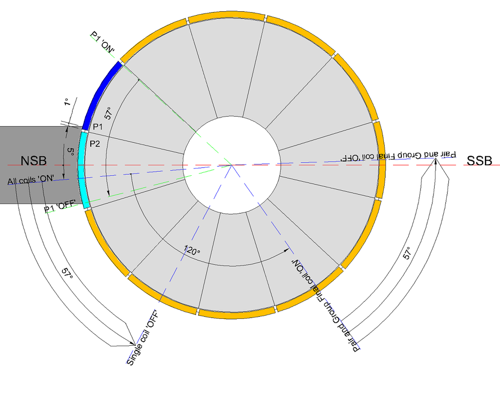
    Happy Hunting

    mark

    Leave a comment:


  • HuntingRoss
    replied
    Originally posted by citfta View Post
    @ grounded

    For all practical purposes there is no delay in the flow of electricity from one end of the coil to the other end. The wire is not like a pipe where you put water into one end and have to wait for it to get to the other end. It is more like a pipe that is already full of water. So as soon as you put water in one end it pushes water out of the other end. Or you can think of it this way. If you push on one end of an iron bar how long does it take for the other end to move? The copper wire is already full of electrons so as soon as you apply a voltage to the wire the electrons start moving. There is no real delay except in an inductor which is something we don't need to go into right now. Even with an inductor as soon as current starts to flow it flows all at once with electrons going into one end of the wire and at the same time other electrons coming out the other end.

    Your idea of winding a coil on the armature with one end being clockwise and the other end being counter clockwise will give a north pole on both sides when the proper polarity of voltage is applied. However, you failed to consider what happens when the armature rotates 180 degrees. Now the brushes will be supplying a voltage of the opposite polarity and so you would have south poles on both sides of the armature and the motor would try to reverse.

    I hope Midaz doesn't mind me chiming in on his thread. Just trying to clear up some confusion.

    Respectfully,
    Carroll
    Ditto. We crossed in the ether.

    m

    Leave a comment:


  • HuntingRoss
    replied
    Originally posted by grounded View Post
    i dont see why a single comm motor cant be wound all north.
    Originally posted by grounded View Post
    there must be a time dealy for the second half of the coil tho.
    Sorry, no time delay, and no difference between single or double comm on this point. Electricity flows between the positive and negative brush in the same way regardless of brush location, single or double comm.

    Originally posted by grounded View Post
    maybe im under-estimating the speed of electricity.
    how fast is electricity ?
    Speed of light. Think of a hose full of water. Turn on the tap and water immediately comes out the other end. The answer is in longitudinal waves if I remember correctly.

    Originally posted by grounded View Post
    i wonder how a single comm motor, mounted with the extra 2 brushes, would compete ?
    Do you mean as motor or generator ?

    Happy Hunting

    mark

    Leave a comment:


  • citfta
    replied
    @ grounded

    For all practical purposes there is no delay in the flow of electricity from one end of the coil to the other end. The wire is not like a pipe where you put water into one end and have to wait for it to get to the other end. It is more like a pipe that is already full of water. So as soon as you put water in one end it pushes water out of the other end. Or you can think of it this way. If you push on one end of an iron bar how long does it take for the other end to move? The copper wire is already full of electrons so as soon as you apply a voltage to the wire the electrons start moving. There is no real delay except in an inductor which is something we don't need to go into right now. Even with an inductor as soon as current starts to flow it flows all at once with electrons going into one end of the wire and at the same time other electrons coming out the other end.

    Your idea of winding a coil on the armature with one end being clockwise and the other end being counter clockwise will give a north pole on both sides when the proper polarity of voltage is applied. However, you failed to consider what happens when the armature rotates 180 degrees. Now the brushes will be supplying a voltage of the opposite polarity and so you would have south poles on both sides of the armature and the motor would try to reverse.

    I hope Midaz doesn't mind me chiming in on his thread. Just trying to clear up some confusion.

    Respectfully,
    Carroll

    Leave a comment:


  • grounded
    replied
    Originally posted by HuntingRoss View Post
    A double comm design can be wound all north, a single comm can't. That's the main difference.
    i dont see why a single comm motor cant be wound all north.

    positive brush in >
    50 winds clockwise >
    loop wire over 180 degrees >
    50 winds anti-clockwise >
    negative brush out.

    its not technically ' all north ' because of the 180 switch, but the layout is the same as it would be.
    there must be a time dealy for the second half of the coil tho.
    i guess the only way to find out is to try it.

    Originally posted by HuntingRoss View Post
    Timing a single comm is easier. There is just one brush board to move.

    The path from the positive brush to the negative brush is equal and simultaneous, so the 'juice' has no preference to either side. No movement of the magnet is required.
    doesnt electric flow into positive, and out through negative tho ?
    there must be some sort of time delay from start to finish. that is where the dual comm design wins i think.

    maybe im under-estimating the speed of electricity.
    how fast is electricity ?
    if a motors spinning at 15 thousand rpm, can it get to the end of a 100 wind coil, before the armature is a degree or 2 out of place ?

    it deffo wins on generation, but i think thats mainly due to having a 2nd brush pack, so it has more points of contact.

    i wonder how a single comm motor, mounted with the extra 2 brushes, would compete. maybe things would be even then ?

    Leave a comment:


  • Midaztouch
    replied
    Singular Coils = A1MoGen

    Here's a quick video on:

    Magnet drag according to Midaz

    Critical angles (bi-sector of the coils should not be in this zone!)

    Buffer zones = Enough room to search for the "Sweet Spot"

    And your "Don't worry be happy zones"!

    [VIDEO]https://m.youtube.com/watch?v=J9bFHg2vYJg[/VIDEO]


    Keep it Clean and Green
    Midaz

    Mark,

    Tell Gary the argument is over Sampojo's 10pole singular coil motor. He's trying to help Dufo with damage control.
    This is a mutiny, NOT a hijacking! The captain has been relieved of duty, due to incompetence.
    Last edited by Midaztouch; 05-20-2015, 06:15 AM.

    Leave a comment:


  • Midaztouch
    replied
    Mark,

    I see your in the mood to kick some serious butt! Keep up the good work!


    That last post that you left Dufo's page was eloquently written.
    Can you please post that to this thread, so people can understand it and discuss it if needed?


    When you made the singular coils, did you happen to test that motor build in series?

    I wish I ran my motor in series before a disassembled it hastily to rebuild it.


    Keep it Clean and Green
    Midaz

    You forgot to tell the Dufo that this steel laminate's will still have some magnetic residual after they disconnected from the power supply.

    Further pushing the coils magnetic field past the magnets bisector.... = more negative magnetic drag!

    That's why the buffer zone is needed!
    Last edited by Midaztouch; 05-20-2015, 06:15 AM.

    Leave a comment:


  • HuntingRoss
    replied
    Originally posted by grounded View Post
    what do you mean by no magnetic drag ?
    When the coil structure attached to the comm segment connects to the brush, it energises that coil structure to be North and they are attracted to the south stator.

    As the comm disconnects from the brush, the North field collapses. As these collapsing north field coils pass the south stator bisector they want to counter rotate the rotor so that they align on the south stator bisector. They are unable to do this under the influence of the constant replacement of new stronger energised north coils coming in from behind them. Inertia of the rotating mass will help to overcome this too. This desire to counter rotate is magnetic drag.

    Happy Hunting

    mark

    Leave a comment:


  • HuntingRoss
    replied
    Originally posted by grounded View Post
    if a single commutator motor can be re-wound half north, and half south, what is the benefit of using this double comm design ?
    A double comm design can be wound all north, a single comm can't. That's the main difference. The coil structures attached to a comm segment are 'OFF' for twice as long on a double comm motor. There is a theoretical advantage there, I haven't tested a single comm motor to the same degree as the OEM as yet with a 4 mile road test. I think I have one now which is a contender and I hope to get my test pilot on that pretty soon. That will answer if the heat build up in a single comm is anything to consider. The OEM after that test was obviously within its parameters but it was too hot to comfortably handle.

    The real advantage is I can chop an OEM, rewind it and test it in one afternoon. It took me (collectively) days to build just one double comm motor before I could do the same. I currently have 5 no. single comm motors because they are so simple to learn from.

    Originally posted by grounded View Post
    the only thing i can think of is the timing......
    Originally posted by grounded View Post
    when your dealing with 100+ winds, the first 50+ winds on north, will hit at the right time, but by the time juice has thrown over to the other side and exited the next 50+ winds for south, the armature might be slightly out of time.
    The path from the positive brush to the negative brush is equal and simultaneous, so the 'juice' has no preference to either side. No movement of the magnet is required.

    Originally posted by grounded View Post
    tesla would have already tried it this way, im sure.... his vision must have been generation.
    what are we missing.
    I'm not saying single comm is the answer and I'm not saying it's not. Until it's properly tested there can be no conclusion. I also don't know if Tesla ruled it out just on the basis that his design shows two comms.

    Until enough of us are playing with bigger motors that can actually do real work then it will be hard to determine if we are missing anything / nothing or everything.

    Happy Hunting

    mark

    Leave a comment:


  • grounded
    replied
    after what you said earlier mark, it got me thinking...
    how am i this stupid ?

    if a single commutator motor can be re-wound half north, and half south, what is the benefit of using this double comm design ?

    the only thing i can think of is the timing......

    when your dealing with 100+ winds, the first 50+ winds on north, will hit at the right time, but by the time juice has thrown over to the other side and exited the next 50+ winds for south, the armature might be slightly out of time.

    shunting the south magnet a couple degrees will probably rememdy this.

    tesla would have already tried it this way, im sure.... his vision must have been generation.
    what are we missing.

    an energy thats invisible and shape-shifts constantly, is hard to understand.
    Last edited by grounded; 05-19-2015, 08:31 PM.

    Leave a comment:


  • grounded
    replied
    what do you mean by no magnetic drag ?

    with permanent magnet motors, the steel armatures always in attraction to the mags

    Leave a comment:


  • HuntingRoss
    replied
    Originally posted by Midaztouch View Post
    [/I]
    Where did you buy your motor and how much?
    Electric Motor 24 Volt 120 Watt 16T Belt Sprocket ES-01 + ES-05 ? PetrolScooter UK

    It's great motor to learn on because it's not too small but it is surprisingly capable in its OEM state.

    Happy Hunting

    mark

    Leave a comment:


  • Midaztouch
    replied
    [/I]
    Originally posted by HuntingRoss View Post
    The single comm solution requires winding a group down one half as 'north' and down the other half as 'south'. It's the major trade off with this design...simplicity of build sacrifices an all north solution. Hence One Pair of Groups.
    Ok, you where just giving info that was said before for the new people.

    But...when I started thinking about this stuff properly. The brush connects two comm segments for 98% of the time. For the other 2% there is only on comm on the brush. So at any one time for the single comm motor there is Two Pairs of Groups connected to the brush.
    Exatly


    If I understand your question correctly it can only be answered by the physical size of the brush board. For my 12 pole motor it was relatively easy with very basic tools. The smaller the motor the more accuracy required to correctly align and fit the brush housings in and get all the wires collected and out of the way.
    Yes, we are on the same page.

    I don't see the wind design as being important to the question, but one thing that does require thought is how you could use extra brushes for motor input on a two stator motor. My extra brushes are for generator output only. If I used them as input they would fire the coils at incorrect angles to the stators.
    Pair & Group coils are too long, the coils' bisectors will cross the bisectors of the magnets. Creating magnet drag. Thou in some cases low, it's still magnetic drag = Extra brushes are impossible!... Don't get me started on the magnetic density of the group coils..

    Singular coils never do that. The A1MoGen always has 0 magnetic drag with Extra Brushes.


    In theory I could fit another pair of brushes on the board and they could probably be fired in the correct sequence to reinforce the rotation. I haven't considered it until you asked this question. In my case I don't think it would be helpful with this size of motor.

    Happy Hunting

    mark
    Your motor is max-ed out, as it is, from extra brushes that you already put on it for GENERATOR ACTION. Those extra brushes you put on, could be wider thou.... Show your brush housing then I can tell/see exactly what your working with.
    You have the perfect motor size for all testing! 12pole 2magnets
    Where did you buy your motor and how much?

    Keep it Clean and Green
    Midaz

    Told you that snake would try anything to get off thar hook? Including showing the samething you showed... Just with movie frames... Same *hit, different day/way!
    Last edited by Midaztouch; 05-19-2015, 01:10 AM.

    Leave a comment:


  • HuntingRoss
    replied
    Originally posted by Midaztouch
    Two pairs of groups!? What are you cooking up?
    The single comm solution requires winding a group down one half as 'north' and down the other half as 'south'. It's the major trade off with this design...simplicity of build sacrifices an all north solution. Hence One Pair of Groups.

    But...when I started thinking about this stuff properly. The brush connects two comm segments for 98% of the time. For the other 2% there is only on comm on the brush. So at any one time for the single comm motor there is Two Pairs of Groups connected to the brush.

    Originally posted by Midaztouch
    With the existing group & pair winds designs on the two commutators motors, can extra brushes fit?
    If I understand your question correctly it can only be answered by the physical size of the brush board. For my 12 pole motor it was relatively easy with very basic tools. The smaller the motor the more accuracy required to correctly align and fit the brush housings in and get all the wires collected and out of the way.

    I don't see the wind design as being important to the question, but one thing that does require thought is how you could use extra brushes for motor input on a two stator motor. My extra brushes are for generator output only. If I used them as input they would fire the coils at incorrect angles to the stators.

    In theory I could fit another pair of brushes on the board and they could probably be fired in the correct sequence to reinforce the rotation. I haven't considered it until you asked this question. In my case I don't think it would be helpful with this size of motor.

    Happy Hunting

    mark

    Leave a comment:


  • Midaztouch
    replied
    Originally posted by Midaztouch
    Padova

    IC we have a newbie here. I was one too you know, a baby as a matter of fact. I bought one of those Imperial motors almost 2 yrs ago for my electric EV build. I followed that thread DAILY and took notes... For over 2yrs.

    I paid for my motor with shipping to Japan. I'm going to use it anyway I see fit. And as you can see, I'm not doing it the way they/he does it... You should be asking yourself why is there Only 1 person working on the 5 pole... that's it, one person!?
    No other motor, just the tiny irregular useless 5pole only! And now that member is finished with it. WTF, now what!?

    Over 20 members have that huge expensive 28pole 45lbs Imperial motor! Lately they are starting to show up! They want answers and growing inpatient!

    If you had a huge thread and people spent REAL money, Some members are in the hole for $$$$$! Would you be busting you butt to make things right and prove your work!? ... Think about it!

    I'm a small time builder who wanted to build an electric motor for my motorcycle. I just got tired of the runaround and same old info a different day. AKA he is stalling!.. I'm nobody special but I'm trying to work with what I paid for. And I'm doing what I thought was interesting and new.

    Don't open your mouth about personal things you know nothing about!... After 3yrs, still on the 5pole and making the same CAD, a different way! #SMH

    Your in for a rude awakening!
    Midaz
    Dufo

    Of course I made my guideline rules about Singular Coils = A1MoGen with Extra Brushes!

    All with 0 Magnetic Drag!!!

    1.) motoring only, you need the magic #5 or greater

    2.) with generator action, you need the magic #6 or greater

    *Number of armature poles divided by number of magnets... If the # is equal to or greater than the MAGIC #...
    It would be wise that you get/buy that motor.

    Examples:

    12poles divided by 2 magnets = 6 poles... Perfect motor for all testing

    28poles divided by 4 magnets = 7 poles.... Perfect motor for all testing = Imperial

    Dufo, copy that and please use it! Hope that help to get this party started over there.


    Keep it Clean and Green
    Midaz
    Last edited by Midaztouch; 05-19-2015, 12:53 AM.

    Leave a comment:

Working...
X