If this is your first visit, be sure to
check out the FAQ by clicking the
link above. You may have to register
before you can post: click the register link above to proceed. To start viewing messages,
select the forum that you want to visit from the selection below.
@altrez,
You will see some unconventional things if you attach a dc pulsed load on the 3rd battery. Such as your pulse motor, or a dc brushed motor, or a controlled pulsed load. It does work.
Randy
From what I am seeing now if you get the load tuned in it draws very little from battery 1 and 2 and charges battery 3 or the battery in the third position as well as the battery attached to the load.
This can only be one of three things. 1. I have had tooo much Gray Goose. 2. My meters are all wrong. 3. Its working!
So many more questions the more I experiment with the Tesla Switch. Today I decided to try a new load. A Radiant charger connected to two 6 volt batteries in series. It seems to work well. I charged 2 6 volt batteries during my first two runs and now I am enjoying the light from the inverter they are producing.
Not sure if anything really has changed from the 12volt 20 watt lamp tho. Yes I can charge a battery using the load and also charge battery 3 at the same time. Not sure where the benifit is right now.
Your load is knocking the potential down to much.. Put your meter on the grounds of the setup and before and after your load and you will be able to see the difference. Scope works too if you got one.
Try to find the loss, then you can find a way to beat it. You'll always loose some in the load the point is how long can you keep going before you have to supplement. And how big is the supplement compared to work output.
Matt
Hi Matt,
So on the negative on battery 3 to the negative on battery 1 and 2? I don't understand after the load, would that just be battery 3?
Still lots of testing going on over here in my make shift lab. I have noticed at the end of my runs that I have lost almost the exact amount of energy used to run the load.
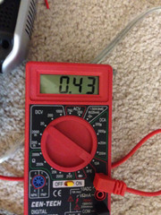
For example I ran a 12 volt lamp setting the voltage around 2.0. At the end of the run my starting voltage had dropped from 26.2 to 24.6. With the meter on the lamp showing 1.58
I still have not got past my starting voltage. And with each run the starting voltage drops a little and the batteries discharge a bit quicker. Also I find it hard to reach even 13 volts for battery 3 on the third cycle as the main batteries are so weak.
Tests for this Afternoon:
1. Controlled load on 3 battery's in parallel timed and logged.
2. Controlled load on Tesla Switch timed and logged
hi turion. in post 186 you mention the prospect of turning magnets on and off.have you checked out electropermanentmagnets.some models flip on-off states with a pulse.not sure if they are happy to do this 50 times a second all day but thought the premise might be worth investigating.
also in post 197 you list desirable attributes for an energizer. inside the automotive thermofan in pic2,the rotor is a flat disk with coils arranged in overlapping loops embedded in what looks like abs plastic or fibreglass.i was curious to pull it apart because i coudn't feel detents or cogging when turning the shaft.there is a big ring shaped mutipole PM stuck to the back of the housing along with 2 brushes.from memory these things draw around 4 to 6 amps at 12-13.8 volts,with the fan blade attatched.i know they can generate because i had an aftermarket set on an old car and if i switched the engine off while the fans were running the engine kept running for a few seconds.hope these 2 items are of some help.cheers
It has been my experience that If you label the two batteries in series 1 and 2, and the load is between 2 and 3, then the battery in position 2 is ALWAYS going to have the lowest charge at the end of a run, and battery 3 the highest.
So 2 moves to the 3rd position to be charged, 1 goes to the 2 position, and 3 goes to 1.
Is that what you are seeing, or are you moving 3 to the 2 position and 2 to the 3 position and leaving 1 alone??
Dave
Hello,
#2 does in fact drain really fast the first few times. However what I am seeing is that after a few cycles it changes almost like a pole flip. at that point battery 1 takes more of a drain then battery 2. Not sure why that is yet but thats what I have been seeing later in the testing.
I think it might be because I am varying the load at different times. I am going to buy some more data logging tools so i can post the results.
Basicly what I am doing is leaving the battery alone with the highest charge for as many cycles as it keeps that charge.
It has been my experience that If you label the two batteries in series 1 and 2, and the load is between 2 and 3, then the battery in position 2 is ALWAYS going to have the lowest charge at the end of a run, and battery 3 the highest.
So 2 moves to the 3rd position to be charged, 1 goes to the 2 position, and 3 goes to 1.
Is that what you are seeing, or are you moving 3 to the 2 position and 2 to the 3 position and leaving 1 alone??
After much testing I have made a modification to my Tesla Switch setup. I now move the batteries in an alternating pattern always replacing the battery with the lowest charge after a run and never letting the voltage drop to a dangerous level on the batteries.
Using that method last night I got to within .6 volts of being back at my starting voltage two times in a roll. It seems to work a lot better. I was also able to bring the temperature almost up to the same level each time.
I did some more testing last night on the battery system. I tried letting the batteries rest about 5 minutes a few times before rotating them. Seemed to have helped a bit.
The one thing I have noticed is that if I start the charging system with a very light load and then adjust it once battery 3 is charging it makes a difference almost like you are giving the batteries time to warm up a bit before adding a higher load.
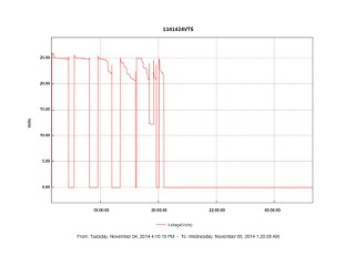
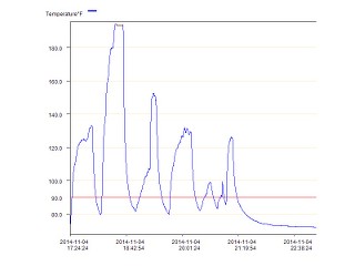
I have not been able to get back to my starting voltage on the series setup between 1 and 2 as of yet. Here is the voltage test from last night.
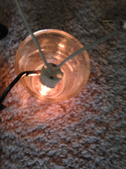
I started off with the motor hooked up to the PWM and setup in generator mode with a 20watt lamp as the load. I measured the temp of the lamp the whole time I was running the experiment.
As you can see I was never able to get the temp backup to what it was when I started with batteries 1 and 2 fully charged.
At the end of my testing I had the lamp connected to the PWM. The light output varies as well as the amp draw.
I plan on more testing later tonight using just the lamp connected to the PWM adjusting the load to get the best charging rate for battery 3 I want to see if I can get past the starting voltage of battery 1 and 2 by the end of the test.
3 motors for 10 dollars. They should only pull 2 amps or so. Little high for the batts you got but not bad.
Matt
Thank you Matt! I just purchased the motors off eBay they will be here on Monday. I also saw your other post about the test leads and tonight I will start making some better leads.
If you were to somehow get the generator to put out 24-26 vdc you could then hook the HOT to the HOT of battery 3 and run the bulb between the ground of the gen and the ground of batt 3 and you would be able to collect that power.
The goal is always to create a potential and catch it after the load. Never let power go to ground.
But in your case you would need smaller motor / gens. The scooter motors are to big for your little batts.
Matt
Hi MAtt,
I could put a larger sprocket on one of the motors to get more voltage but its also going to draw more current so you are right, I need bigger batteries or smaller motors. Can you please recommend a smaller easy to find motor that I can try for this project?
Makes things easier to visualise what I am trying to do. The only problem I can see with the way you have drawn it is if the load needs correct polarities to function. But Im sure I can work around that.
Loving this simple switch btw. Wish Id got around to building it earlier. The Li-ions are working well. Looking at trying some LiFEPo4 soon. A little more forgiving with their charge and discharge voltages than their LiPo cousins. Got me thinking about a three battery switch for my quad copter. Everyone else is stripping weight and optimizing motor/esc combos then shorting it all to ground in a vain attempt to increase flight times. Id really like to get into the nitty gritties of ESC design. Seems to me from what schematics I can find to be a simple H bridge mosfet switch, some sensored, some sensorless. Can only imagine where that will lead if you could juggle potentials AND recover energy from the brushless esc.


Leave a comment: