This forum is preserved as a permanent archive. The community continues at eMedia Press.

Announcement

Collapse
No announcement yet.

Cap Dump Circuit

Collapse
X
 
  • Filter
  • Time
  • Show
Clear All
new posts

  • Dave45
    replied
    Outstanding thanks Matt
    We'r on the same page
    Hope you dont mind I added ionization electrodes to the circuit.
    Leave a comment:


  • Matthew Jones
    replied
    I wouldn't drive 12 fets with single driver. You'll get heat in some and not in others, cause they are not all going to match and you will have hard time matching them. Some will have more resistance at the gate and that will be enough to stop it from fully charging.

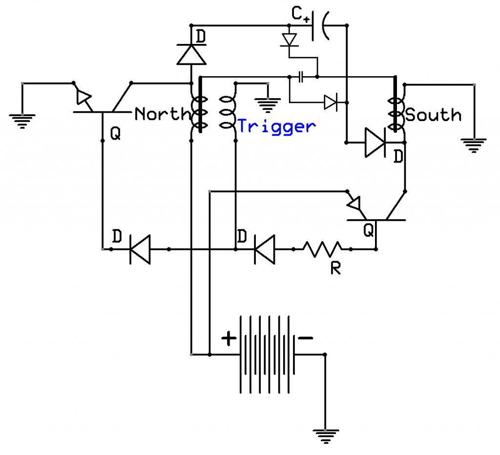
    Here is that circuit. Mind you its just the basics, to show you how the power flows, no specific parts.


    This will fill a cap quicker than just charging the positive side. you will need 2 separate coils one (North) wound beginning to end clockwise with the trigger winding and the other (South) wound counter clockwise. Do not take clock wise wound coil and run it backwards. This causes BEMF in the coil to reject input power and causes an imbalance. The first windings that receive power should always be closet to the iron core. Do not use a toroid or transformer body as they are designed to contain the magnetic field.

    The north coil will produce a positive spike the south coil will produce a negative spike.

    Now I understand the temptation to drive this circuit with high power. IE fets and drivers but you are not going to get the return you expect. You want large coils with as little input power as you can stand and bunch of them if you want higher results. Its just like a monopole or joule thief the point is to use as little power for as big a spike as you can get.

    This circuit if built and tuned correctly can double your available power. I have done it many times.

    I'll add a few details tonight and repost it.

    Good luck.
    Matt
    Last edited by Matthew Jones; 06-12-2014, 10:43 AM.

    Leave a comment:


  • BroMikey
    replied
    Originally posted by Matthew Jones View Post

    With what your doing you could get away with driving the gate .5 amp at 18 volt. That will turn that fet on faster than you need.
    The bigger the driver the more you have to suppress transient response on the gate circuit. So get ready for that if you move up.

    Matt
    Yes thats why I chose this one because it might actually be ABLE to turn on 12 MOSFETS like I use, all at the same time and have enough power to do it.

    Or even 6 IRFP460's would make my day. I will be using this same circuit for a large joule thief (JOHN BEDINI SOLID STATE ENERGIZER) in generator mode operating at 9khz as always.

    How many is the question. How many IRFP460's can I turn "ON" effectively with that big half bridge?????

    That's the question. The circuits I work on require that I drive more than one or two fets so I think using one driver to power as many as possible makes more sense in the long run. Less problematic all of the way around.

    Fewer parts all driven by one driver would be awesome. As it stands I am looking at one driver for 2 FET's and that makes for 6 drivers and 12 devices.

    Then I wonder how could 6 driver chips be put in sinc??? And the list goes on.

    Will they all pull together

    Will the drivers all fire perfectly at the same time or will there always be more deviation going this route???

    You see what I mean about the 12 fets being driven by a single driver?

    There is a 9amp driver also.

    Mike
    Last edited by BroMikey; 06-12-2014, 01:34 AM.

    Leave a comment:


  • Matthew Jones
    replied
    You don't exceed 18 volt on a gate. Most can only handle 24 volt or so but that is real stress. Only feed it 18 volt.
    With the calculator you can figure out how many joule in the gate and you can use whatever method or driver to charge it to that point as fast as you need to. Faster turns ons mean less heat loss less wear and tear.

    I'll work on that circuit tonight.

    Matt

    Leave a comment:


  • BroMikey
    replied
    Gotta Git

    Originally posted by Matthew Jones View Post
    Thats a duel N channel driver. It will work but IXYS Fets and IGBT's use larger gate capacitance, so a high amp driver is the way to go to get them moving fast.
    Those Fets you using don't require that much. And really you not moving that fast, you only have one shot every so often. At most 2-3 times a second so if you want a high turn on rate you can add more capacitance to the driver side for a pretty quik turn on. Search "Bootstrap drivers in Power circuits"

    With what your doing you could get away with driving the gate .5 amp at 18 volt. That will turn that fet on faster than you need.
    The bigger the driver the more you have to suppress transient response on the gate circuit. So get ready for that if you move up.

    The biggest thing you need to do is learn to calculate the need for power at your gate. All gates have a different capacitance value, and thats what dictates the power of the driver along with the speed the circuit is running.

    @ Dave45
    You lost me with the magical stuff....


    Matt
    I will be back later but wow this is what I need right here, what you said about gate times and capacitance. I checked that number at my gate and I think it was 2500PF??? I think so using the calculator?

    Is that what I should do? Use a capacitance joule calculator?

    Then based on THAT number of joules as long as I do not exceed the value I won't fry my gates, right? I think this must be right.

    This is the way I found out about "Turn ON"

    By the way thanks for pointing out the special FETS required on that last half bridge.

    (1) I put a 10k base to emitter and 500ohms base to supply and proceeded to raise the voltage from 8vdc to 24vdc (My homemade supply won't go any higher yet )

    (2)Next I changed the 500 ohm to 200 ohm now and "ON" times went from 500uS to 200uS at the higher voltages like 15vdc and for my fet this is good.

    (3) Now I use a 100 ohm to base for a 1 uS rise


    So experimenting with more gate capacitance sounds pretty KOOL


    Mike

    Leave a comment:


  • BroMikey
    replied
    Now yer talking my lingo

    Originally posted by Matthew Jones View Post
    Thats not hard to do. You have complicated too much using a buck and boost circiut.
    You can build self resonator to deliver power to both plates. Works alot as you described with a PNP and NPN.

    I'll draw it up for you. I have one the garage if I get time I'll film it for you.

    Basically all you need is a Joule thief type circuit with trigger in one of the coils. You can branch trigger to drive both a NPN and PNP with 2 diodes in the opposite direction.

    I'll draw it up.

    I built that about 8 years ago.

    Matt
    @Matt

    Glad to hear you say that Matt.

    That's a great idea because the the joule thief can be self adjusting.

    Mike
    Last edited by BroMikey; 07-08-2014, 07:20 AM.

    Leave a comment:


  • Matthew Jones
    replied
    Thats not hard to do. You have complicated too much using a buck and boost circiut.
    You can build self resonator to deliver power to both plates. Works alot as you described with a PNP and NPN.

    I'll draw it up for you. I have one the garage if I get time I'll film it for you.

    Basically all you need is a Joule thief type circiut with trigger in one of the coil. You can branch trigger to drive both a NPN and PNP with 2 diodes in the opposite direction.

    I'll draw it up.

    I built that about 8 years ago.

    Matt

    Leave a comment:


  • Dave45
    replied
    Look at Mikes cap dump circuit

    The bemf from the coils are pumping massive pos energy into the cap and battery but nothing on the neg side.
    When all that pos energy hits the cap it creates a neg deficit on the other side of the cap, the battery has to fill this deficit.

    Our circuits need to collect bipolar, pos and neg.

    Leave a comment:


  • Dave45
    replied
    Nothing magical at all, no quantum entanglement or particles popping in and out of existence, just plain and simple separation of the aether into pos and neg using ionization and a collector circuit to gather the energy.

    Look into air purifier's and static eliminators, study the buck and boost circuits.

    A buck convertor increases amperage at the expense of voltage.

    A boost convertor increases voltage at the expense of amperage.

    There are pos and neg energy's at work in a circuit, we are taught to use conventional view where energy flows from the pos to neg but there is also energy that flows from neg to pos.

    We have to allow for and collect both.

    Leave a comment:


  • Matthew Jones
    replied
    Originally posted by BroMikey View Post
    Yes thank you Matthew Jones

    How about this chip? It has a good high voltage ceiling or the same as my MOSFETS IRFP460's at 500volts????

    This stuff is being uploaded to my site here it is.

    BroMikey's Science Projects

    Will this IX611 chip work??? It is a half bridge?? About any half bridge will work? Isn't that what you said Matt???

    Or am I looking for something more specific????

    I am compiling information on my webpage.

    NOTE:
    I have been pulsing on three 460 fets about 2 weeks at 12vdc. Those big batteries in the basement both got charged and I have used the power off of them at night.

    Today I switched back to 24vdc (Both banks) and began charging and in one hour one of the fets popped.

    Three devices is just not enough and I am thinking 4 X 3 devices so I will solder them all into there places this time instead of running on 1/4 impulse power Scotty.

    Mike
    Thats a duel N channel driver. It will work but IXYS Fets and IGBT's use larger gate capacitance, so a high amp driver is the way to go to get them moving fast.
    Those Fets you using don't require that much. And really you not moving that fast, you only have one shot every so often. At most 2-3 times a second so if you want a high turn on rate you can add more capacitance to the driver side for a pretty quik turn on. Search "Bootstrap drivers in Power circuits"

    With what your doing you could get away with driving the gate .5 amp at 18 volt. That will turn that fet on faster than you need.
    The bigger the driver the more you have to suppress transient response on the gate circuit. So get ready for that if you move up.

    The biggest thing you need to do is learn to calculate the need for power at your gate. All gates have a different capacitance value, and thats what dictates the power of the driver along with the speed the circuit is running.

    @ Dave45
    You lost me with the magical stuff....


    Matt

    Leave a comment:


  • BroMikey
    replied
    Goodness Me

    Originally posted by Dave45 View Post
    The simple things catch my eye, like why does a pos pulsed coil give a neg return like the buck converter.
    And why does a neg pulsed coil give a pos return like the boost converter.

    No matter what we do we are pulling from the battery, we have to have a source be it radioactive material or another form of energy.

    The aether - a big misunderstanding
    The earth is negative
    The ionosphere is pos
    Between neutral
    So where is the aether
    When lightning exchanges charges between the pos an neg an ion channel creates the path that allows charges to flow.
    In a bipolar ionization circuit neg ion clouds form around the pos electrode and pos ion clouds form around the neg electrode.
    Now I know ions are not electrons or positrons but as we can see in the lightning example they allow energy to flow so it would make sense to put the neg pulsed coil of a boost converter in a pos ion cloud and the pos pulsed coil of a buck converter in a neg ion cloud, we just might find our source without using radioactive isotopes and we might just discover this elusive aether that everyone talks about.

    If we take a look at how static eliminators work the pos and neg electrodes are brought close together and close to the work surface that needs neutralized the ions pos and neg join together and become neutral particles-- sounds like that neutral layer between the earth and ionosphere doesnt it

    Static eliminators give us an indication of something we dont want, if the two coils of the buck boost converter are wound on the same core any ionization that occurs will be eliminated because of the close proximity.
    The two cores and their electrodes should be separated.

    The electrodes should blunt with no sharp points or edges we want to pull charges from the atmosphere not emit charges from our circuit.

    The ionization circuit and collecting circuits can be separate circuits running at different frequencies.
    @Dave

    When you talk like that it gives me ideas. Very good to hear something other than kill the dipole as Tom B. always says.

    That boost circuit sounds like it could evolve into more than just a send/receiver going down hill, rather possibly a magnifier.

    Mike

    Leave a comment:


  • BroMikey
    replied
    6amps Driver

    Originally posted by Matthew Jones View Post
    You only need 4 N channels for that controller because it uses a high side and low side driver. Why though are you wanting to blend both a buck and boost. Does your input have that much variation?


    1.5 amp is the power to the gate.

    Matt

    Yes thank you Matthew Jones

    How about this chip? It has a good high voltage ceiling or the same as my MOSFETS IRFP460's at 500volts????

    This stuff is being uploaded to my site here it is.

    BroMikey's Science Projects

    Will this IX611 chip work??? It is a half bridge?? About any half bridge will work? Isn't that what you said Matt???

    Or am I looking for something more specific????

    I am compiling information on my webpage.

    NOTE:
    I have been pulsing on three 460 fets about 2 weeks at 12vdc. Those big batteries in the basement both got charged and I have used the power off of them at night.

    Today I switched back to 24vdc (Both banks) and began charging and in one hour one of the fets popped.

    Three devices is just not enough and I am thinking 4 X 3 devices so I will solder them all into their places this time instead of running on 1/4 impulse power Scotty.

    Mike
    Last edited by BroMikey; 06-11-2014, 10:31 AM.

    Leave a comment:


  • Dave45
    replied
    You only need 4 N channels for that controller because it uses a high side and low side driver. Why though are you wanting to blend both a buck and boost. Does your input have that much variation?
    The simple things catch my eye, like why does a pos pulsed coil give a neg return like the buck converter.
    And why does a neg pulsed coil give a pos return like the boost converter.

    No matter what we do we are pulling from the battery, we have to have a source be it radioactive material or another form of energy.

    The aether - a big misunderstanding
    The earth is negative
    The ionosphere is pos
    Between neutral
    So where is the aether
    When lightning exchanges charges between the pos an neg an ion channel creates the path that allows charges to flow.
    In a bipolar ionization circuit neg ion clouds form around the pos electrode and pos ion clouds form around the neg electrode.
    Now I know ions are not electrons or positrons but as we can see in the lightning example they allow energy to flow so it would make sense to put the neg pulsed coil of a boost converter in a pos ion cloud and the pos pulsed coil of a buck converter in a neg ion cloud, we just might find our source without using radioactive isotopes and we might just discover this elusive aether that everyone talks about.

    If we take a look at how static eliminators work the pos and neg electrodes are brought close together and close to the work surface that needs neutralized the ions pos and neg join together and become neutral particles-- sounds like that neutral layer between the earth and ionosphere doesnt it

    Static eliminators give us an indication of something we dont want, if the two coils of the buck boost converter are wound on the same core any ionization that occurs will be eliminated because of the close proximity.
    The two cores and their electrodes should be separated.

    The electrodes should blunt with no sharp points or edges we want to pull charges from the atmosphere not emit charges from our circuit.

    The ionization circuit and collecting circuits can be separate circuits running at different frequencies.

    Leave a comment:


  • Matthew Jones
    replied
    Originally posted by Dave45 View Post
    Thank you Mr. Jones
    What Im trying to do is combine the boost converter and the buck converter into one.
    I found a chip that does this but I want to be able to change and experiment with different configurations.

    Here's the boost buck chip


    Sorry Mike dont mean to derail your thread.
    You only need 4 N channels for that controller because it uses a high side and low side driver. Why though are you wanting to blend both a buck and boost. Does your input have that much variation?

    Originally posted by BroMikey View Post
    No need for all of that Dave
    You are doing a great job in my book. This all applies.
    Here is Matt Jones suggestion on my website
    BroMikey's Science Projects
    1.5 amp is small for my fets but we could look around for higher output chips.
    @Matt
    Pretty Kool suggestion
    Mike
    1.5 amp is the power to the gate.

    Matt

    Leave a comment:


  • BroMikey
    replied
    Yes I understand

    Originally posted by Shanjaq View Post
    tried to edit this in but the forums didn't want to cooperate: The idea here is to jam the switch between its high and low impedance state as fast as possible so it isn't dissipating too much power through the drain-source junction, which would vaporize in short order given the case of a purely capacitive load. If you have multiple power supplies you can communicate control signals between them using a level shifter in a similar fashion to how opto-isolators are used, but response times are much faster.
    Okay I understand this idea. Can you give more shift level examples that are good circuits???

    What shift level chip are you talking about in your work?

    Thank you for your important idea.

    Mike

    Leave a comment:

Working...
X