
Crazy
"path to follow according to their skills."
so the real reason comes to the surface. you don't have the skills or are afraid of part G. nothing wrong with that Hanon, just holding back this thread that's all. just because you don't have certain skills is no reason to post the low road distraction game.
NO you can't do that with a device like part G, that's plane ridiculous.
that's like building a Rolex using Mickey Mouse parts, no one would do that.
just because you don't see what UFOP and I do is no reason to sidetrack the real patent part G device.
it might be good advice to choose an easier device for you to build Hanon,or find a person to help you, just saying. when i tell people about this device most say they would love to help, just ask someone.
"I just can assure that at high rpm the moving brush revolving around a normal commutator will loose contact because of the centrifugal force."
last time i checked there is nothing normal about the figuera device at all. since brush will be on top that wont be a problem.
Cademan;
wow ! that's a big core, might want to use only one core but the rest sounds great.
how many volts. ??
also a good idea is the paper clip on a straw. shows where the fields are in relation to the secondary. (thanks D)
MM
-
Well, I'm shooting for just about half of that, 2.5 and 1.5 just to start with. I wound my G on two 820 VA cores so 3280 VA total, using the autotransformer values @ 2X VA.Originally posted by marathonman View Post
48 turns of #12 THHN which exactly fit the ID and just happens to be the number of turns returned by the formula using the cross section of these cores.
Actually it's 16 coils of 3 turns series connected giving 16 taps.
Now I'm anxious to finish the switch & see how it does.
CMLeave a comment:
-
Timing
Been doing some figures referring to my transistor controlled part G.
at 60 hz, that's 60 revolutions in 1 second. 1000 ms devided by 60 = 16.6666 ms per revolution. 16.666 devided by 16 transistors = 1.041 ms on time per transistor. that my friend is not much time to get hot.
i found a cheaper transistor from the one i was going to use but it is To-247 not To-264 like i built the board for. low and behold i realized the pin spacing for both are exactly the same. yeh ! no board change.
people fail to realize Transistors have a S.O.A that's safe operating area that must be followed. that is why i choose such healthy Transistors is to give a little head room. if this is not followed say by-by to your barbecued Transistors.
pic below is S.O.A. chart of a typical high power Transistor. the power dissipation for this particular one is 890 watts so you see i have plenty of head room and wont stress the transistor out.

MMLast edited by marathonman; 09-19-2016, 04:05 PM.Leave a comment:
-
In spanish " Sea R a resistencia ...."
In 2012 I translated it as " Let R be a resistance...." (resistance in general sense)
An the dictionary gives these possible translations

I think this thread must move on. All us have already posted our own views. Now everyone may decide whi h path to follow according to their skills.
RegardsLeave a comment:
-
I have no idea. A possibility: I just can assure that at high rpm the moving brush revolving around a normalcommutator will loose contact because of the centrifugal force. For that reason I posted a proposal for a static brush with a rotating commutator and 7 slip rings to avoid that problemOriginally posted by Ufopolitics View Post
I guess that by mistake you wanted to say "milliwatts" not milliamps. Current (intensity) is maintained, but voltage decreases, and less useful power may be exteacted. If you introduce 1 A you will return 1 A , but at near zero voltageFiguera, who was an Electric Engineer must have been "very" aware that current when passing by such high number of resistive components, is going to be wasted, converted in heat basically in a majority of it...and whatever "returns" to generator....would be literally "nickel and dimes"...milliamps if something is left.
In reality, current never "returns", and contrary to that there would be a very high demand from "where it was taken from" (generator, external source)...instead of any return at all.
,So, Figuera speaks about currents on his device as if there would be absolutely zero losses
Figuera describes that the machine needs a part of the produced power for the continuous excitation of the machine. I do not know if that was a big amount or a low amount...
Well...in fact I have a home heater with 2000 watts power and using around 10 A at 220 volts. I do not understand your point , a common 100 watts incandescent light bulb at the voltage in USA uses exactly 1AAccording to your previous paragraph from Buforn, that "current" Figuera was referring to...was just One (1) Amp!!...for God sake!!!
One amp would get burnt in a matter of seconds by going through all those resistors and coils in less than a full cycle of that brush!!!
There are some references in this thread that with resistors and 100 watts input then an output of 300 watts was measured. So it seems resistors may get COP > 1 unless that those resultls were not acurrately measured.
Really and honestly I would love that toroidal part G would be a part of the whole generator because it has many advantages over resistors, but I read the patent and I do not see that described in the patent. But this what I interpret reading the patent. And I have always tried to promote replications as close as posible to those described in the patent. The patent just use the spanish word "resistencia" that I translated in general mean as "resistance" instead of using terms related to the electricity and electronic field "resistor". I think it is good to know that when I translated that in 2012 I was a newbie into electricity field, I did not even have a multimeter, so it is normal to use a general translation for that word when you are not into this specific field. If a person dealing with this field would have been translated the patent maybe he had used the specific term into this field.
You may think of myself whatever you want but I just try to be honest and follow the patent principles. I already posted that patent must have sufficiency of disclosure to be valid.Leave a comment:
-
"Hey Madmack...oops!!, sorry, meant Marathonman...
Just kidding friend!!"
NOT FUNNY
In my first rotating commutator set up i used one commutator, two slip rings for Set N & S and resistive wire instead of resistors.
the thing actually put out more then in contrary to belief. it sure got hot though. using resistive wire to me was better allowing me to get the exact resistance i needed but no self sustain.
that's when i realized no resistors were used in the Figuera device and confirmed by my mentor. since the information was passed to me about part G i have studied very intensely since. the primaries were kind of easy to figure out, part G was the real puzzle
he used a 100 amp alternator with brushes in the fan assembly, modifying the core to be even on top to wind over. just as i have been so adamantly preaching about the design.
not only do i think Figuera was a quiet, well refined Genius, he had one hell of an imagination.
Cadman;
Even if you used more amperage to excite the primaries as long as you have enough primaries and proper size part G core it will be all right.
i am shooting for 5 amp to high primary and 2.5 to my low primary with a 1500 va part G. with as little ohms on my primaries as possible because part G controls the currant not the other way around. biggest bang for my buck as to say.
MMLast edited by marathonman; 09-19-2016, 03:15 PM.Leave a comment:
-
Don't be distracted by 1 amp and 100 volts, it could be a red herring. Besides, if 100 watts can be turned into 2000 watts then that 2000 could be fed to a larger unit to produce 20000. It was very common to use a small DC generator to excite larger AC generators back then.
CMLeave a comment:
-
Hey Madmack...oops!!, sorry, meant Marathonman...Originally posted by marathonman View Post
Just kidding friend!!
Seriously now...I believe using resistors would "elementary" prove concept about his patent, not going OU, not doing COP>1, but it will prove that by displacing the virtual fields, there would be induction shown at secondaries...end of deal.
Definitively, I agree there with you above.referring to the second possible material patent ??? it could of been a reality if he wouldn't of died and Buforn hid it. or maybe he was protecting the one thing the was very special to him, his pride and joy part G. ???
You're completely right...it was Buforn who wrote the one amp @ 100V deal.one thing that bothers me though about the one amp at 100 volts.
the amount of winding involved would be extremely high and self inductance would be through the roof. this would cause the reaction to currant change extremely slow and detrimental to the operation of the device.
trying to keep induction, winding's low at 1 amp is darn near impossible.
you have to consider the source, it was Buforn not Figuera himself.
MM
If You look at a conventional house generator head...the rotating constantly fed "Fields" are built based on a pretty high resistance (over the 60 to 120 ohms), while the resistance at the "Static Coils" or "Self Exciting Coils", here considered the "Second Secondary"...it only have between one (1) to two (2) ohms...get the "hint" on this difference?
The difference refers exactly to what you are writing above...while the constantly fed and spinning coil (field) have 60 ohms , the static one must be of very low self inductance, so it is very low ohms and still in every cycle it have such high response to the point it "refills" the huge resistance coil in order to project the required magnetic field to achieve induction...still passing by diodes resistance and stored in a very low capacitance value electrolytic cap...
Regards
UfopoliticsLast edited by Ufopolitics; 09-19-2016, 02:17 PM.Leave a comment:
-
Resistors in this device would be insane proposition. even the patent says resistance NOT resistors. yet it is still an issue for some ? why !
referring to the second possible material patent ??? it could of been a reality if he wouldn't of died and/or Buforn hid it. or maybe he was protecting the one thing the was very special to him, his pride and joy part G. ??? maybe buforn just didn't talk more about it because he didn't understand it. who knows.
one thing that bothers me though about the one amp at 100 volts.
the amount of winding involved would be extremely high and self inductance would be through the roof. this would cause the reaction to currant change extremely slow and detrimental to the operation of the device.
trying to keep induction, winding's low at 1 amp is darn near impossible.
you have to consider the source, it was Buforn not Figuera himself.
MMLast edited by marathonman; 09-19-2016, 02:17 PM.Leave a comment:
-
Originally posted by hanon1492 View PostComo se ve en el dibujo la corriente una vez ha hecho su oficio en los diferentes electroimanes vuelve al generador de donde se ha tomado;a reusable liquidAs it is noted on the drawing, once current has done its job on all the electromagnets returns to generator, where it (current) was taken from;mientras los primeros van de corriente se van vaciandoTo the point that Figuera considers only a "small amount" to be drawn off secondaries to excite machine and motor, making it a "Self Runner"...and still put out 20,000 Watts!based on when the first (set) are filling up with currents, the second ones are emptying out, and so, by repeating this effect continuously and in an organized manner, is maintained a constant alteration on the magnetic fields, inside of which is set the induced circuit, without any more complications than the turning of a brush or set of brushes that move in circle around cylinder G based on the action of a small electric motor.
According to your previous paragraph from Buforn, that "current" Figuera was referring to...was just One (1) Amp!!...for God sake!!!
One amp would get burnt in a matter of seconds by going through all those resistors and coils in less than a full cycle of that brush!!!
And honestly...here we only have two ways to conclude about all of the above...:
1- 2- Figuera did not provide the specifics about his method to recycle those currents, that allow him to treat them as a reusable fluid, back and forth...simply because it was not part of the main idea he was trying to protect in that specific patent. Which is creating a Solid State Generator based on Virtual Magnetic Field displacement back-forth along the induced cores.
So, the method to achieve just that purpose on its "elementary form" was clearly reflected there by using "simple and easy resistors".
The specifics about the recycling of Current "Apparatus" was material of a second patent...which never took place because he died before (Figuera died a few days after filing this patent in 1908) .
Concluding here...I do not believe Figuera was a dumb engineer as I wrote on part 1...but a genius that knew exactly what he was pursuing to protect in that specific patent.
The more I read this patent (in Spanish) back and forth...the more I believe in my number two(2) option above.
Regards
UfopoliticsLast edited by Ufopolitics; 09-19-2016, 01:23 PM.Leave a comment:
-
Part G
Part G.
A time-varying current in a ferromagnetic inductor, which causes a time-varying magnetic field in its core thus inductance will not remain constant but will change with the current through the device as the brush rotates, adding and subtracting copper winding's and ferromagnetic material in the process of movement. thus left with two independent feeds raising and lowering currant values in unison.
the energy loss per low cycle of AC like alternating current is constant and low in a closed core system compared to an open core. with the constant recycled energy of the reducing electromnaget, the spinning vortec of opposing magnetic fields and heat and wire losses being replaced buy the second secondary allows this device to be self sustaining putting it in a category of it's own.
MMLast edited by marathonman; 09-18-2016, 11:22 PM.Leave a comment:
-
Where my apology
HANON;
You owe me an apology for your insult to me. retract your post or be a man and APOLOGIZE. which ever you choose just DO IT.
RETRACT YOUR POST LIAR.
MM
Leave a comment:
-
100% Agreed on that. The main principle are two magnetics fields in repulsion expanding and contracting in unisonOriginally posted by Ufopolitics View Post
Let 's look for our common goal and let's look for The Truth
Edit: I translated the spanish word "delga" as "commutator bar" because I didn't know any other better way of translated into english (electricity is not my field). Ufo, maybe now you could give us a better translation for that word. It is a word not very frequently used now https://es.m.wikipedia.org/wiki/Delga
 Last edited by hanon1492; 09-18-2016, 08:12 PM.
Leave a comment:
-
R box
If you really want to be specific, the "R" box you are referring to does not have zig zag lines like resistors always do, from the days of Praxii.
they in fact have wavy lines indicative of coils of wire or INDUCTORS.
below pic is exactly what i mean so if one disagrees maybe one should consider a refresher in electronic symbols.

Well imagine that !
Ignoring the truth in front of your face or redirecting does not make the truth go way, it just conferms your intelligence level and understanding capabilities.
MMLast edited by marathonman; 09-18-2016, 08:09 PM.Leave a comment:
-
Hanon,Originally posted by hanon1492 View Post
I am sorry, but no one "skilled in the art" would see resistors there, but coils, solenoids or inductors.
Below is a copy of page 149 from the September Edition of "Electricity" Magazine from 1901...:
[IMG]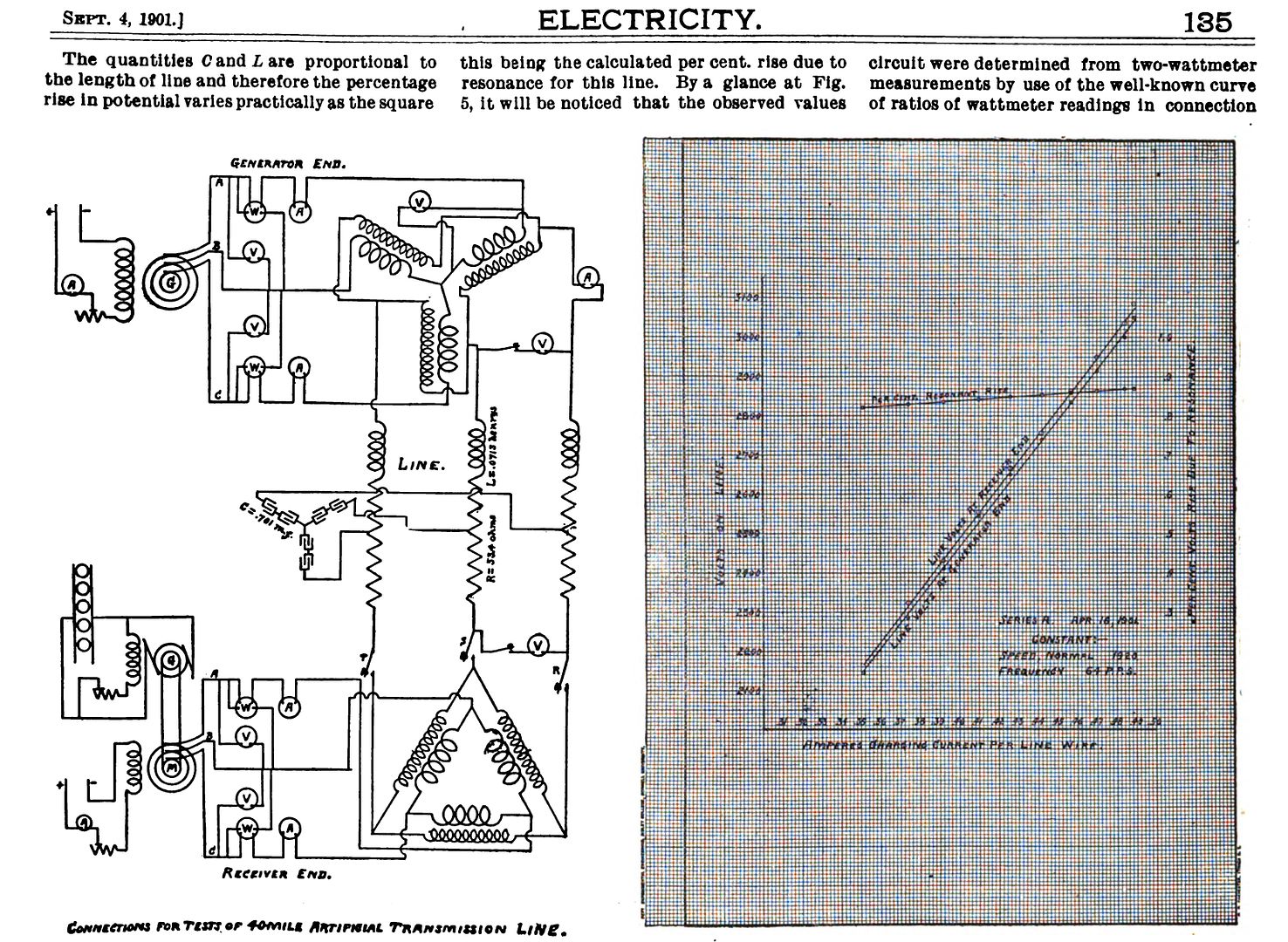 [/IMG]
Please note the Electric Circuit Diagram on that page at left...have very clear both symbols...Coils/Inductors "L" and Resistors "R"...repeatedly all over diagram
See the difference?
I do not think that Figuera, who was very aware of the works from Clarke, Faraday, and Pixi...in Europe (England) and America...will make such a mistake by "painting" the wrong symbols that were in accordance at that time for resistance.
IMO, this "wrong" symbols were done completely on purpose inside that "R" Box.
Regards
UfopoliticsLast edited by Ufopolitics; 09-18-2016, 07:12 PM.Leave a comment:

Leave a comment: