If this is your first visit, be sure to
check out the FAQ by clicking the
link above. You may have to register
before you can post: click the register link above to proceed. To start viewing messages,
select the forum that you want to visit from the selection below.
I just read over the patent (translation) again. There is no mention of a toroid. Part G is called a cylinder and it is said the brush touches 2 contacts.
I have seen where you claim to read between the lines. I tend to take what I read at face value, especially patents and other legal documents.
Finally someone has read the patent in detail. Thanks bistander !!!
Anyway , you should know that some people just will answer you...keep on reading between lines. You have to think out of the box...
Figuera wrote "resistance" , and in my view this is very different to "reactance", although it may also work, even with less losses. But it is not what it is written in the patent.
Note also that the cylinder is said to be " of an insulating material". . Well, what everyone just call a commutator to connect the different resistance pieces.
Why would you increase wire size, that's nutz considering Figuera did it with one wire size 108 years ago. beside the fact Figuera was not using wire resistance to control flow, he used inductive reactance dynamically on the fly so all you have to do is change contact points whether it was a brush or transistor taps.
there is no short circuit of turns in part G, where in the world did you come up with that.?
the first graph you posted was really good, do you have a secondary output graph for that.??
ps. sorry UFOP, your graph currant directions do not ever change so you graph is incorrect, they are right voicing concern.
MM
Hi MM,
I just read over the patent (translation) again. There is no mention of a toroid. Part G is called a cylinder and it is said the brush touches 2 contacts.
I have seen where you claim to read between the lines. I tend to take what I read at face value, especially patents and other legal documents.
BTW, partA in that Tesla patent is an AC generator.
I was particularly bothered by Ufo's diagram of a toroid inductor partG. But the discussion following that has me wondering if any partG relying primarily on inductive reactance would be worth the trouble. If the analogy can be made to the excitation in a shunt type conventional DC generator, it will be on the order of a few percent of rated power output for field loss. Like a couple hundred Watts for a 10kW unit.
A) Why would you increase wire size, that's nutz considering
B) Figuera did it with one wire size 108 years ago.
C) beside the fact Figuera was not using wire resistance to control flow, he used inductive reactance dynamically on the fly so all you have to do is change contact points whether it was a brush or transistor taps.
D) there is no short circuit of turns in part G, where in the world did you come up with that.?
MM
a) Just ""1) One example is to wrap the toroid..."" You have mention 'brain' sometime
b) Are you really really sure?? Just ONE size? Oh'Boy...
c) You have to consider the coils internal Cu-resistance
d) If ?? you use a construction like a VARIAC, they make shortcuts between wraps.
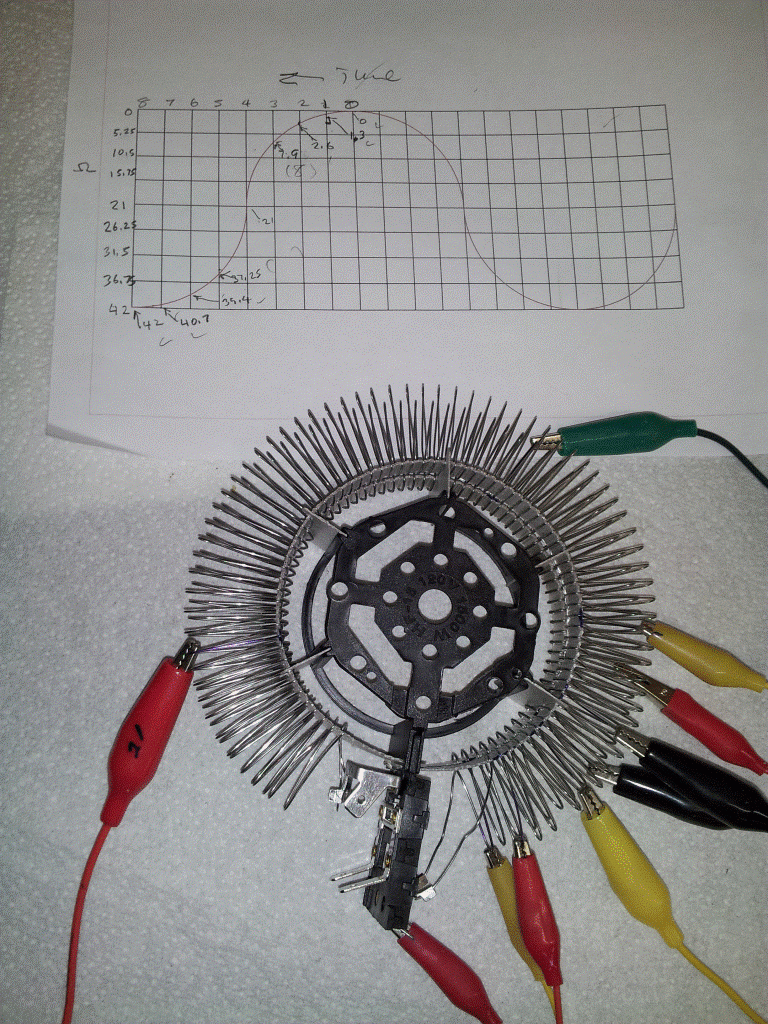
Well always you can follow the patent guidelines an use a resistance as the user in ou forum which is really ingenious, easier to debug, easier to built and easier to tune for a first proof of principle device. See the ingenious way to adjust the resistance in each step just with some clamps and the resistor from a heater:
And even better if you use to symmetrical resistors in order to get symmetrical results while sweeping the resistor with the contacts one way or the reverse way. I posted that some weeks ago.
All (10) G-inductances replaced with 1 mH 1ohm
Input: 23.8V 2A R load 130 Ohm
Arne
Thanks Arne.
Well we can see that the toroid is going to be difficult to tune, especially in the case of a rotary brush touching sequentially turn to increase/decrease the inductance. Your choice... Tune= Wind + Test + Rewind to adjust the proper number of turns required
Really strange that reversal in the current. I did not expect it. Also 51% of output power to input power is a surprise.
2) Another thing I noticed is your going in the negative region, meaning your using Ac.
MM
1) From answer to Hanon; ""Arne, could you simulate the same system with equal inductance in each segment, as happens in a rotating brush case design?""
2) Output from sec.y-coil. Sorry, I can't help it some God involved?
1) Well perhaps any skilled in the art may show how to get that same sinewave with a rotating brush, which have equal incrementents of inductance between two contacts. I can not.
2) What is the number 51% that you remarked in your sketch?
1) One example is to wrap the toroid with gradually increasing wire gauge against the connection points to the N and S coils. (N.B. NOT equal incrementents!) Then the Henrys and internal resistance reduces when the brush approaches the tappings. A square number in the math is involved here too with fewer turns. If I'm right?
But I don't like a brush here. It always have to short-circuit some turns of wire. That's bad!
2) Thats a rougt number! Comes from Input: 23.37V 6.3A about 147W
Output: 142V p-p over 130 Ohm about 75W
What happened to your graph.? the first one you posted was perfect, the second looks like it had a seizure.
i to am curious as to what was the significance of 51%???
another thing i noticed is your going in the negative region, meaning your using Ac. sorry but it won't happen with the figuera device. any pole reversal induction will cease and primaries will produce heat degrading magnetic field.
i don't have a sim program but would like to see it at 100 volts DC.
->MM, Hanon
Notice the different (mH) G taps to achieve "sinewave" in my post #1265
Arne
Well perhaps any skilled in the art may show how to get that same sinewave with a rotating brush, which have equal incrementents of inductance between two contacts. I can not.
Arne, could you simulate the same system with equal inductance in each segment, as happens in a rotating brush case design? If so please show the intensity axis to see the values. What is the number 51% that you remarked in your sketch?
Yes this simulation is intended for a static device with no moving parts. The G coil with taps can be wound on a toroid for best performance or a double U-cores for winding convenience but with more magnetic losses. The "brush" is simulated to go back and forth connecting to the G-coil segmens as in the patent and have both winding ends open (on a toroid) but connected to "N" and "S".






Leave a comment: