If this is your first visit, be sure to
check out the FAQ by clicking the
link above. You may have to register
before you can post: click the register link above to proceed. To start viewing messages,
select the forum that you want to visit from the selection below.
Everyone on this forum should be studying the A vortex field, this is the field that exchanges energy from one coil to another in a transformer, this field is kinetic whereas the magnetic field is static.
Im not sure if you have seen this experiment Bloch Wall - YouTube Im sure this is a coil powered with ac but it needs to be done with dc,with pulsed dc, with an iron core, with a toroid core, with a brass core, with a copper core, every configuration one can think of.
I kick myself as much money as I have spent researching this I have not bought a scope, that will change very soon its first on my list.
I agree this needs to be the year that we find and implement free energy for all.
GSM Im glad a man of your intellect is here and studying this, sometimes I have to read your words over and over, I am just a simple layman and think in layman's terms but Im trying to keep up
I agree we are dealing with particles that have a gyroscopic spin, the faster we spin these particles in a magnet-vortex field the more energy they acquire.
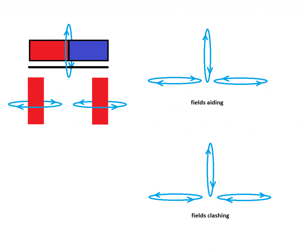
The problem I had studying the fields is the system is an ac system, that means the current is changing directions through the buzzer coils, therefore changing the field direction of the coils and how this relates to the magnet which does not change, this is where the iron comes into play.
With iron in between two magnets you can have n to n or any combination the iron is allowing the magnets field to be altered, so therefore when the buzzer coils fields change directions their not opposing the magnets field, it flips around the iron.
I may try to draw it up later when I have more time.
I wonder if anyone here has been following Eric Dollard's predicament. I don't agree with everything Eric says, but we all have our own understandings, and it is quite inconsequential as to whether anyone's intermediate understanding is wrong - if - they have a WORKING KNOWLEDGE !
Eric, I know you are pretty pissed off, and for obvious reason because TPTB don't want the World to know that which you already know could be applied. It is also far too easy to think of the majority population as TPTB do - as an unknowing people not worthy of sharing Earth's bounty, which is happening at this very moment. Eric - please go invite yourself to a Christmas dinner with someone at similar hands-on and intellectual level to yourself.
Well - This morning I too woke up feeling pretty pissed off too. I have spent over 2 years studying and brainstorming many *supposed* forms of free energy especially the Hendershot generator. I have come to learn that most of devices (on this forum too) are either hoaxes, or misunderstandings or willfull dis-information, often for purposes of fraud.
W_T_F_U guys !!!!!
Energy does not appear out of sparks, transients or space, especially not from within closed electromagnetic systems, and also not farther away either, because transducible invisible radiation always originates from an energised material source !
So this morning I wondered how I could get readers here to understand how the Hendershot generator works, because I have already stated it in this thread and no-one has yet picked up on it. It is the case that my explanations have been spread through the thread - and - maybe not everyone has read the whole thread, so I'll try again.
Everything we are and experience is down to SPIN. Matter, energy, radiation - these are all spin related phenomenon - NOT vectors, NOT mathematics.
Beyond this we know of electric charge flow, magnetism and gravity, again all spin related.
Dave. Good drawing.
When the keeper is thin, and the buzzer windings are connected to the mutal field connected Hendershot core-cap coils, the keeper field becomes reversed due to on-going buzzer coil field reversals introduced by the iron sleeve core windings. Individual core-cap windings are in phase opposition at opposite ends of the sleeve, but the field induced at the centre of the sleeve is transformerd to low source impedance and phase shifted via a series connected capacitor in order to set up a central region of field rotation within the short circuited core.
At every core to buzzer field reversal the polarisation within the keeper flips like a whip from end to end, thus maintaining core-cap synchrony, before cycling phase reversal the other way.
Morpher you have put up some interesting links.
1) That patent. Low energy electron ? All electrons are the same, so does the writer mean charge or velocity. He writes as if he there is some different particle he is utilising. Ever checked up on the 'Hoverboard' company owning that Patent ?
2) Brown utilised radioactive material - safely though - as now used by the military, but not we who pay their wages !!!!!
3) Magnetic amplifiers - clever use of technology, but these merely control a supply of already existing energy, and I am not yet aware of any such device other than Wesley Gary being used to control permanent magnetic fields as way of electrical generation, though I have considered using iron wire/ flat strip gating, and I might still try same.
Dave, please take your drawings to the next stage - make your 'fields' show the associated electron orbit spin alignments !!!!!
Electrons are like little gyroscopes.
Electrons in a magnetic field are like gyroscopes in gravity.
If you rotate (spin) an already magnetised (spinning) magnetic domain in a magnetic field it is like rotating the axis of a gyroscope in Earth's gravity, and the electron (gyroscope) experiences force on an axis normal to both spin directions.
With gyroscopes the force transfer can either be away from the Earth as demonstrated here - Professor Eric Laithwaite gives a demonstration of a large gyro wheel - YouTube
or - towards the Earth, where the gyroscope (electron) would effectively become so heavy with respect to the Earth (atomic nucleus) that the eminent Professor Eric Laithwaite would be unable to support it.
So a spinning magnetic domain (electron gyroscope) within a magnetic field will lead to forces beyond which normal electron motion (like atomic alignment relationships as used in MRI scanning) can be sustained, and an electron could either be forced away from a nucleus as with Laithwaites gyroscope generation, or INTO IT !!!!! Electron Capture - YouTube
Look at the Hendershot windings. They are in opposition between ends, and phase shifted close to the centre. They set up a buzzer impulse driven/ maintained spin wave within the thin Iron metal sleeve cores. In order to induce a physical domain spin the shorted turn sleeve core must physically resonate longitudinally - phonically within - magnetic phonons - this to artificially induce atomic change from Iron to Manganese within some centrally activated central region of the core, and thus with an associated gamma radiation output.
Read and check out page 10 here = 16/86 in the pdf.
The 'electron capture' generated gamma radiation will pass out to and induce electron emission from the central aluminium capacitor overwind, which, if connected in the correct electrical sense, will cyclically and differentially transduce/ generate output which energises both the main output winding plus maintain generator operation. I am not sure that this capacitor represents the best conversion arrangement, but hey, it worked !!!!!
I am not learned enough to know whether there would be any harmful emanations from these assemblies, and this is why a have written that a geiger counter should be used for safety reasons. Though better than that, would not a geiger counter provide evidence of circuit tuning leading to sustained operation ? This also is why I use the expression of *core-cap* within the winding assemblies, for these are what must be exchanged as the iron becomes used up and turned into a manganese oxide almost indistinguishable from ordinary iron rust. This also relates to the description of electrostatic generator given to Hendershot's device after he died, for the electrostatic charge originates within his especially hand-made capacitors from the matter devolution artificially induced within the thin iron sleeve cores. Hence the Hendershot generator was the most important design we have witnessed being suppressed, and its energy was not magnetically sucked from the Earth, nor received from the Cosmos.
Please folks, stop imagining energy appearing from without and being impulse attracted - all energy is already within matter itself as it devolutes from large to small atomic elements after being exploded outwards from stars, and then becomes compressed back into heavier elements as new stars form within our infinite and forever continuing universe.
Folks, please get thoughts about this sorted and make 2013 a good year unbound by PTB indoctrinations and FALSE teachings.
Happy Christmas everyone.
Cheers ............ Graham.
I'll video the sudden effortless armature 'neutral zone' field reversals as soon as possible.
So I have a puzzle for you guys to ponder.
Given all the Hendershot components, do you think it would be possible to make a magnetic multivibrator circuit (ignoring the circuit diagrams from the Hendershot material ... and instead attempt to wire things up in multivibrator fasion)?
The Hendershot coil has "tickler" coils and there are types of oscillators (amplifiers), Armstrong comes to mind, that have tickler coils.
The solenoid-magnet-bar could be the amplification control for the oscillator.
I think rather than being influenced by the Hendershot material, if you were just given these parts, could you make a multi-vibrator from them?
That is my question? Using a battery to power it is OK. We will worry about how to power it some other way later.
It might be possible to find such a circuit on the web.
More inspiration for you guys.
-morpher44
Hi Morpher,
I should like to discuss via sharing opinions upon your analysis.
Hi Graham,
I would have to agree with you that it probably is not a galvanic reaction in the Hendershot device. I just put it out there as something to look at. If it was Galvanic, and if you could make the thing self-run, chances are you would see signs of Galvanic reactions on the metal.
I have to also agree that the cylinder was probably ferromagnetic (and NOT diamagnetic). However, it also occurred to me that his hand-made capacitor IS diamagnetic. The Aho material his "measurements" of the inductances. I think if I remember correctly, they are measurements w/o the cylinder in place. Certainly when adding the ferromagnetic material, the tunning would DROP from 500Khz down to something LOWER in frequency. This would be like the ferrite-rod that you can pull in and out of a coil to "tune", as you change the inductance that way. With the diamagnetic capacitor in there as well, you have an even more complex effect on the inductance. The spinning field in the currents in the coils would be inducting crazy Lenz law stuff in the capacitor -- applying PRESSURE to it, and altering its capacitance. With everything so WIGGLY here, it would be difficult to measure anything ... and maybe that is the key. You actually want to create highly unstable, highly glitchy, circuit, with all sorts of spikes making the physical vibrations increase and the glitchyness increase, etc. So you would actually want to build the thing as SLOPPY as possible to increase glitchiness. Just a thought.
Re: Magnetic Amplifiers
I only mentioned them as something that people might want to read up on, since there are circuits that are PURE coil, with magnetic controls, magnetic tuning, histerisis, etc. The concepts are useful when discussing the Hendershot device. I admit I need an education on these. I've studied a little book on them, and find them completely perplexing. I have to study circuit analysis, impedance, KVL, KVC, watch some MIT lectures, etc.
I had speculated that Hendershots crazy magnet-solenoid thing was just some sort of "control" to lower or increase power and bring it to that subtle feedback balance point -- resonance. Certainly there is some sort of crazy positive-feedback thing happening -- so studying oscillators that do positive feedback might be useful too.
>Also 'Phi' could not be related to the relatively low frequencies at
>work here. You had me puzzling over this for quite some time after
>I first saw your YT videos Morpher !
I got onto the idea of PHI because of things I've read about the
Hubbard coil. Hubbard had always claimed that Hendershot had
stolen aspects of his design (idea). Hubbard had used PHI for some
reason. I figured out, partially, why Hubbard used PHI. It was quite
obvious really. It had to do with how many cores he used. He
selected 8 smaller outer cores, and one larger central core.
With circles drawn on paper like that, you get the PHI relationship.
Hubbard was inspired by the Flower-of-Life, and may have
selected his coil design just from that idea.
Had he used 6 outer cores, I think the central area would fit a core
exactly the same size as each of the 6 -- if I remember that correctly.
Now, on to Hendershot.
I puzzled over 57 pegs and found, to my amazement, that there is a PHY
relationship there as well.
What I don't know, is WHY and whether or not there is a coincidence here
or something meaningful.
But as Richard Hoagland used to say, "the math does't lie".
Hubbard later went on to be a proponent of ACID, so that guy was out there a bit. There really is a story here for an interesting movie.
re: Spice
I've never used that ... so I was just guessing it could handle it.
Perhaps a better way of stating what I was suggesting is that a computer model of some sort, perhaps written with your own hand-written code, could be used to model the Hendershot device. I would love some way of visualizing the magnetic fields -- using proper Quaternion physics ALA Maxwell's equations. Video game programmers know now to use Quaternion math for FAST calculations of complex rotations in their physics models. Go Programmers!!! Stupid Heaviside simplification. Gimbal lock! Doh!
The phonon stuff you describe is over my head. We do need some physicists to chime in here and tell us we're all wet. :-)
re: Wesley Gary
Yeah when I was making my videos, someone turned me on to Wesley's stuff. I made a video or two trying to do something like this -- with no success. Of course mechanically, I'm quite challenged. So I gave up on that idea.
I'm thinking that like tuning for resonance with a very narrow band, the so called neutral zone is probably almost "impossible" to find unless you've really machined the thing nicely.
I also like the Leedskalnin, perpetual clapper idea, which I've proven to myself would indeed create a very LARGE, high voltage, narrow pulse, IF and only IF, you could pull the keeper off the electromagnet. Doing so would take quite a bit of force -- and again a major mechanical challenge. In looking at the pictures of Hendershot's device, I don't think he had anything that clever. I think he was instead just gently pushing the solenoid toward the keeper-magnet to "tune" the feedback. My impression. If I'm wrong this device is going to need EAR protection for its user's, and really piss off the wife.
>Could the continuous output have come from the fine single magnet
>buzzer wires alone
I would guess no. I think the entire system he has is this strange positive feedback machine that requires just a little bit of power input (possibly arriving into the capacitors as electrical disturbances happen around the planet), and then that gets the mechanical stuff vibrating, which induces more current, which builds fields larger, which induces more current, and so forth until you have to BACK-OFF the solenoid and find some balance point. Some of the material describes Hendershot using a "starter battery", just to get it going, and then he would disconnect it. Certainly big caps will hold a charge for a while, and if you have the TESLA-SWITCH idea going on where currents are just flowing back and forth and a LOW-RESISTANCE-LOAD (like a bulb), is just your way of seeing the currents go back and forth ... then you can not really think about it as a load. Its just a small value of R so that your time constant is LONGER. If your machine gets another PING, it can ring again, another PING ... ring again. Keep those incoming pings going and you might sustain -- like a rock guitarist holding his guitar against his AMP.
I do agree with the conclusions of others that it is very unlikely that Lester used radio active materials.......
Here are some conclusions I have come to, which may or may not be correct, but I try.......
Hi Morpher,
I should like to discuss via sharing opinions upon your analysis.
There was nothing galvanic in the Hendershot Mk3.
The original Hendershot generators were indeed related to Lester's use of Iron (Fe) in TIN cans, these as shorted turn sleeve core inductors = high current reaction to buzzer transient impulse = induced electron orbit spin, thus electron spin within spin, resulting in force upon electron normal to both spin axes and electron impact/ capture by Fe nucleii. Tin additionally emanates when photon excited.
(Check out Meyer-Mace.)
Kapanadze uses a shorted metal turn inside his long coil overwind, where the field from the load current increases the atomicly induced photonic emanations transduced by his multilayer coil overwind, whereas Lester used aluminium foil for core emanation transduction which he fed back to the core.
I worked hands-on with magnetic amplifiers; they do not generate energy, merely control already existing supply via low power core saturation control circuitry.
See photo of the Hendershot Generator board showing operation with the illuminated lamp and clamp tuning adjustment; there the buzzer was nowhere near the core-caps, though these were clearly close together in a field coupled relationship.
Basketweave was of its day and a finished varnished/ waxed assembly could be cut from its construction board to be moved about for mutual alignment coupling. Also 'Phi' could not be related to the relatively low frequencies at work here. You had me puzzling over this for quite some time after I first saw your YT videos Morpher !
Spice will not work. Spice relates only to 'scientifically' known phenomenon, not unknown shorted sleeve core molecular domain characteristics, phonon relationships related to core length, and possibly internal magnons too.
Regarding the buzzer keeper alignment.
Obviously the keeper must be on the magnet when not in use, though it must be oscillated in the buzzer assembly *neutral zone* as priorly described by Wesley Gary, and as subsequently re-described by Mark Hendershot, with need for fine screw thread optimum positional adjustment wrt magnet.
Could the continuous output have come from the fine single magnet buzzer wires alone, where 60W equates to ~1/10th horsepower, and the Hendershot drawing planned for a 500W device ?
I did read your info on the 57 peg Phi related coil winding. I used the same and have wound a 3" basket weave coil as my first coil in a series of 8 coils for the Mk1 device. That was great information, thanks.
I will keep your other comments in mind as I continue. I am not sure what to expect yet.
The other 7 coils yet to be wound will take a little more thought. (wire size and length, turns, resistance, interaction, etc.)
Thanks again for your comments.
@clarence,
Sorry Clarence, you were right. You did a good job of researching those capacitors whether they are used or not. Keep posting your ideas, all information is important they are like a well that might spring forth new thoughts.
Hello mikec_ut,
clarence,
I sincerely respect your gracious efforts in your posting sir. I have had to learn to be focused on purpose of the threads on all venues of threads. I hope to have learned to receive the good honest valuable information that each poster gives. whether it is just a small tidbit or a high knowledge content I believe all are given not in self interest but in the interest of all of us members. that is the value of monitoring the daily posts given as they become available. again I thank you for your consideration sir.
I did read your info on the 57 peg Phi related coil winding. I used the same and have wound a 3" basket weave coil as my first coil in a series of 8 coils for the Mk1 device. That was great information, thanks.
I will keep your other comments in mind as I continue. I am not sure what to expect yet.
The other 7 coils yet to be wound will take a little more thought. (wire size and length, turns, resistance, interaction, etc.)
Thanks again for your comments.
@clarence,
Sorry Clarence, you were right. You did a good job of researching those capacitors whether they are used or not. Keep posting your ideas, all information is important they are like a well that might spring forth new thoughts.
I am new to Hendershot and this forum and have read as much as possible on all of Hendershot devices.
Hi mikec_ut
Re: the coils.
I did make a video where I present why I think Hendershot used exactly 57 pegs. The math involves PHI and is quite easy and logical. He may have just wanted a certain spacing between pegs so that the wires cross each other at a nice angle, not too steep, not too perpendicular. Just right. This might be useful to know in case you want to make the coils a different size than Hendershot and wanted to maintain that same wire-crossing angle.
Basketweave coils are pretty amazing in that they are real easy to wire up. You don't have the back strain and anxiety of winding just a cylinder straight, with each wire touching. A basket weave is a much more natural winding that even a kid could do w/o being overly bored. You can watch TV while your doing it and you won't mess up. It doesn't require your full attention.
The Wire diameter (gauge) and wire types are a mystery. Certainly larger gauge wire would offer less resistance, which is good. I would put each cord on its on 1/2 inch board and put a spool of wire on a large dowel nearby.
I would NOT put the thing in WAX until you've managed to get something working and "tuned". I doubt the WAX-PARAFIN is required to make it work. I could be wrong, but in terms of building and testing electronic equipment, like radios, usually you would only WAX things at the end to hold things in place in a stable way. WAX does have some interesting properties, however.
You might need to invest in a meter that can read inductance. This can be expensive. If you don't have that, you might be able to make a simple LRC circuit, and attempt to measure the time constant by pulsing it periodically. You would then need to do math and derive the inductance L knowing R and C. Or get some old wheatstone bridge thingy for measuring inductance -- really old school.
It probably true that you want your two coils to MATCH, inductance-wise, for each of the L1, L2, L3, L4 coils -- adding and/or subtracting wire until that is so. I bought a little kit that measures inductance, but its kinda crude.
Another thing that I ran into was I was using all sorts of clip leads, wired this way and that like the set of some Beatles stage. Not cool in this case. You want all your interconnecting wiring to be NEAT and away from the coils and with adequate spacing, etc. The skin effect and mutual inductive coupling where you don't want it to happen can really mess you up. Just bring an oscilloscope probe over into high-voltage AC circuits can be a bit tricky.
Oh yeah, if you have a nice SCOPE, be careful. You don't want to damage your scope with a high-voltage SPIKE it can't handle. You might keep probes nearby but not attached or make little pick-up coils for your probes to read the AC via the fields -- being careful with inverse-square-law considerations. I would hate to see someone DESTROY their oscilloscope on Christmas or something.
NEVER have your laptop or computer near this stuff ... or mobile smart-phone, or tablet. Not a good idea. Consumer devices are NOT going to like pulsed, glitchy, high-voltage, electronics near them.
Rubber gloves. Yup. Bare foot. Nope. Touch hot wires with only one hand and use the back of your hand first, don't grab. Never both hands.
Keep little kids and kittens away.
If you do power it up with some power source, I recommend using 12V gel batteries (or smaller batteries) and not your house main. You are less
likely to kill yourself.
Little cheap NEON bulbs are a good FIRST load to shoot for, not a 60Hz, 60Watt incandescent. NEON is actually quite sensitive and easy to light up -- even using a 1.5v AA battery and some oscillator to get the voltage high enough.
Clarence.
That circuit is a HOAX.
The Hendershot circuit does NOT use those values !
Cheers .......... Graham.
Hello GSM,
clarence,
I was not advocateing ANY particular circuit AT ALL. all I did was post some complete accurate non disinfo about some capacitors and sources for same that had been asked for a short while ago by some members on this thread!!!!!!!!!!!!!
I did try to display that info in a manner to show that persueing those capacitors was just not very advantageous. Regardless of what they wanted to use them for!!!!thats their business not yours or mine!!!
please do try to stay in focus sir.
To all,
I am quite aware of I would say the majority of all the Hendershot circuits AND I have not treated them lightly. I have read them and reread them for hours!, includeing the one that is condemned as a hoax. my opinion is still out on that one but I lean towards a positive direction. however, KNOW this, my end opinion will be justified or unjustified by haveing replicated it thoroughly and experimenting with that replication as necesscary to reach a justified conclusion!!! however I am not going to persue this replication immediately as I am presently still occupied in another type. one at a time-one at a time, but I will keep up with all the valuable posting that becomes available on this thread.
To me, the MOST intrigueing thing about any form of the Hendershot generator systems is the fact that there is no apparent battry involved in the systems at all. thats like throwing a bone in front of a hungry dog.
Leave a comment: