
As promised for completeness. The figures for the single comm earth/ground shaft build -
Using 0.425mm wire @ 0.121 ohm/m
12 groups
3 coils per group
15 turns per coil
All earthed to the shaft at the bottom of the groups
I didn't do a resistance test per se but did a calculation based on metres used per group which is 5.2m giving approx 0.63 ohms.
Connection this time was via both wires using the body as the output.
10.34v PSU no load
10.26v @ 1.04A @ 2280 rpm with 4.74v output.
Stall amps approx 5.6A
5.39v PSU no load
5.16v @ 0.92A @ 1080 rpm with 2.64v output.
Stall amps approx 3.4A
For comparison. The OEM motor.
10.3v @ 1.18A @ 1546 rpm.
I couldn't pinch the shaft tightly enough to stall. Amps was 7A and rising.
5.22v @ 1.18A @ 763 rpm.
Stall amps approx 5.9A
--S--
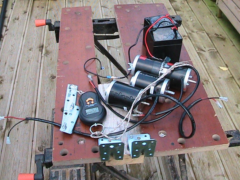
The test today was to rig for measuring torque. It's rough and ready and serves as comparison between all 3 motors.
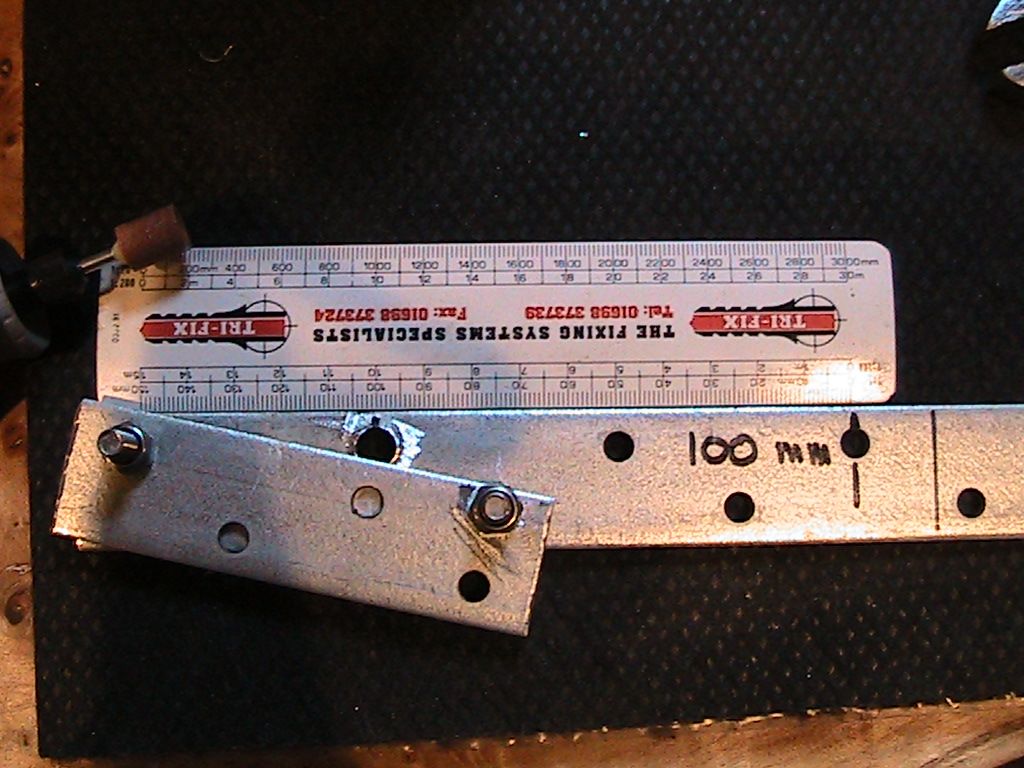
The arm that I fabricated weighs 175g with the centre of mass 10mm from the shaft centre. Close enough that I discounted the arm from the calculations.
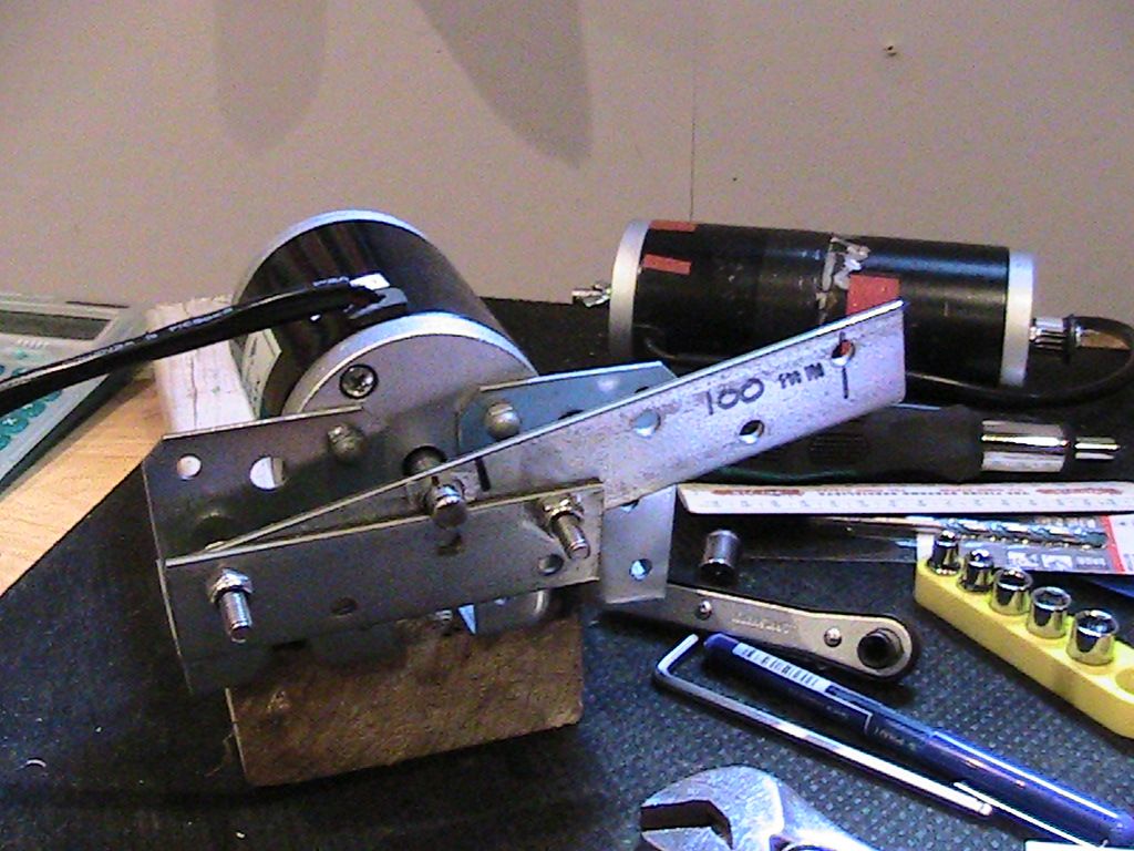
The principle for operation was to manually support the arm perpendicular to the ground (floor) with the balance suspended from the arm and tethered to the ground. Switch the motor on and the balance would record the load applied by the stalled motor. The initial reading drops then stabilises, where, after 2 seconds the balance 'locks' and records the stable result.
24v Battery (from scooter)
OEM. 1.125kg @ 100mm [0.1125 kgm = 1.10 Nm]
Single comm. 0.355kg @ 100mm [0.0355 kgm = 0.348 Nm]
Beast (2 comm). 0.610kg @ 100mm [0.061 kgm = 0.598 Nm]
The OEM is rated at 0.42 Nm @ 2500 rpm...not 1.10 Nm. What ever the reason for the discrepancy, for a baseline test the OEM has almost twice the torque of the Beast and four times the Single Comm.
Keep hunting
mark
[IMG]URL=http://s652.photobucket.com/user/huntingross/media/IMG_2762.jpg.html]
 [/URL][/IMG]
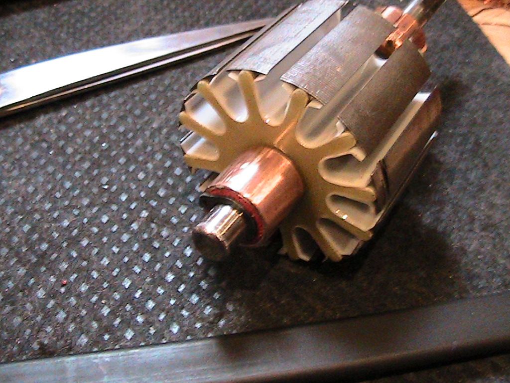
Pic of the copper collar at the base of the single comm motor.
[IMG]URL=http://s652.photobucket.com/user/huntingross/media/IMG_2764.jpg.html]
 [/URL][/IMG]
Pic of arm in fabrication.
[IMG]URL=http://s652.photobucket.com/user/huntingross/media/IMG_2766.jpg.html]
 [/URL][/IMG]
Pic of motor mounting bracket with arm attached to shaft.
[IMG]URL=http://s652.photobucket.com/user/huntingross/media/IMG_2768.jpg.html]
 [/URL][/IMG]
Pic of all 3 motors for testing.


 ...and it should draw much less amps there. From that point on towards South He would be timing it towards a higher Attraction Mode...decreasing to even more amps...but sacrificing power/torque and speed.
Leave a comment: