
Originally posted by HuntingRoss
View Post
-
Beast #4 Timing - 4+4 pole Pairs
Hi UFO
Timing of the 4+4 pole pairs. As you can see the timing is way over in the attraction. It was slow to accelerate but got up to a good speed but the torque was pretty low.
[IMG]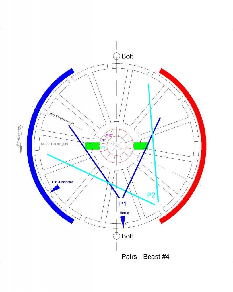 [/IMG]
I'll hopefully have this wired by the weekend.
happy hunting
markLeave a comment:
-
Thank you Sampojo. That makes sense...it's the harmonic reinforcement thing...ripples in the pond.
In my inexperienced eyes, my immediate thought for your ammeter was the pulse frequency was too fast to register on the scale, but electron fumes sounds cool.
Snap on the construction thing. That is how I built mine, and I used wet rags on the outside to keep the magnet area under temperature with a series of spot welds.
Regards
markLeave a comment:
-
Exactomundo Re: my Very Promising Post Last post Page 242
Originally posted by HuntingRoss View Post
Quite Right Mark!
Pulsing: What UFO shows on his My Motors thread ( I urge you to study all the ~100 pages) is how to get radiant energy out of a coil by pulsing and then how to apply it to a motor's coils. But in a nutshell you may maximize RE by pulsing coils sequentially at a suitable low frequency. In multi-stator asym designs you may 1/2, 1/4,1/6 depending on the number of brush pairs/stators, the amount of input power theoretically needed to run the motor by a normal unpulsed direct feed. You can skip over the 555 board designs to focus on the monster driver John Stone V5.1 and Arduino Programmable Logic Chip designs. I need to confirm this but even my dual stator motor was running on electron fumes, hundreds of milliamps, off scale of my 20 amp ammeter, when it normally would take 1-1.5A.
Construction: If a conventional symmetric motor body is not machined to asymmetric specs, (matching diameter shaft, interchangeable brush mount endplates) then they must be made to spec. One easy way to achieve this is the practice of sawing off the butt end of a symmetric motor flush to the magnets and joining the bodies there, leaving two brush mount ends on either side. Of course you must find a strong connection mechanism and the bodies must be made true. In these motors, no need to dismount magnets. I arc welded the bodies together. Heating of magnets must be minimized or else they lose their magnetism. I go for bigger motors that can take things like arc welding since the heating is rather instantaneous and can be controlled by using heat sinks like a damp rag on the inside. (Soldering will actually deliver more heat to the magnets than welding since its not as fast as arc welding.) This way you have doubled the size and strength and energy output capability of the motor by using more of the old symmetric components!
I'd like to make an additional comment on the stepper motor effect I saw, I don't recall any one posting about this before, for the entire 2 years! Is the motor saying it is liking operation at specific rpms, i.e. frequencies, i.e. HARMONICS anyone???? i.e. maximum zero point energy tap points???? Hmmm One of Tesla's favorite topics as I recall!!!!
I am truly excited...Last edited by sampojo; 12-02-2014, 02:45 PM.Leave a comment:
-
Thanks UFO.Originally posted by Ufopolitics View Post
I will post the timing diagram for Beast #4 later tonight. It is as your diagram but advanced by one segment...ie towards attraction. It was slow and weak. Hopefully retarding by one segment will improve its performance.
Regards
markLeave a comment:
-
Leave a comment:
-
Hi Sampojo
I think I know why we would want to pulse the input...but could you indulge me please and give a brief 'low tech' explanation.
Also, if I'm understanding the terminology correctly "double rotor (1) dual stator (2) unipolar (3) winding" means -
(1) Two original rotors used back-to-back to achieve two commutator asym arrangement.
(2) The stators from both OEM bodies have been used
(3) All north
I know you'll have this detailed somewhere in the 240 pages of this thread, so apologies for asking you to briefly go over it again for newbies (me).
Regards
markLeave a comment:
-
WOO-HOOO Great Results with my AMC and unipolar motor
Very preliminary. Got my AMC fired up finally. I had a gremlin running around the mosfets on one board, seemed to have a bad one after I converted my boards to quad-mosfet construction after burning up a couple mosfets. It was on the board that I used Kog's method of going to the terminal from the heat sink. This has a great trouble shooting advantage as you can simply disconnect each mosfet and isolate it without having to unsolder!!! Slowly started disconnecting the Mosfets, seemed to detect a fault once but then could not. When first connected this channel would run the motor even when the Arduino was not pulsing. slapped things backed together taking some shortcuts to test the board, had to assume it was gonna work, and it did!!
So here are my results. When pulsing, probably around 1KC at full on, my GM window double rotor dual stator unipolar winding did about 3450 rpm. I need a more sensitve ammeter, cause it was like it wasn't even flinching. when run as direct feed it takes at least 1.0+ amps. I ran it direct feed both brush sets, and got about 100rpm more. Close enough to compare for now! So it didn't even want to register 1 tick (1/2 amp) on the AMC and direct feed I know it takes about an amp.
VERY PROMISING!!!
Something also very odd. As I slowly increased the duty cycle, the motor stepped up rpm like a stepper motor in about 5 distinct jumps, as opposed to smoothly with the rotation of the duty cycle potentiometer?!?!
Standby as I will measure this up, down and sideways in the next few days. I have to redo the shortcuts, etc. Also posted on the "My motors..." thread.Last edited by sampojo; 12-02-2014, 04:55 AM.Leave a comment:
-
UFO
I am watching your Art on the new gen thread and you are dead on with your ideas. Keep it up.
DanaLeave a comment:
-
Let's get to work...
Hello Mark,Originally posted by HuntingRoss View Post
Yes there was a bit of frustration...I wish I could take a fast transport, go there to your Lab, spend a few hours and fix your problems...but, unfortunately it is not possible...human barriers.
Thanks for having so much patience and for being so persistent in this builds!
Let's give this structure another "face"...let's make it a Four Pole per each Coil, instead of Three:
[IMG]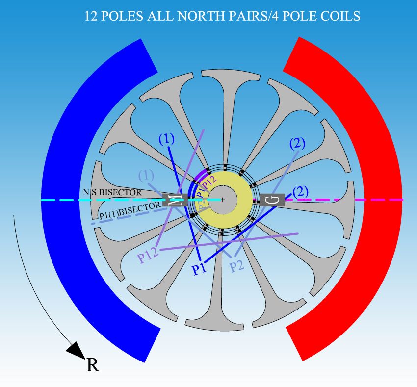 [/IMG]
There was a mistake I made when I wrote that your 'needle' to align timing was the center of both coils, as you have pointed in your above diagram...I apologize for this mistake.
It is wrong, in Pairs there are Two Separate Bisectors that We must consider when making the proper timing alignment, each Coil have a separate Bisector right at the center, in this case (4 poles coils) it would be the center slot between the 2+2 poles.
In the above Diagram (my Diagram) I have pointed out the Bisector for P1, Coil 1 as P1(1)BISECTOR
Please note that the perfect Timing alignment must be done at the position of rotor in Diagram above, or when Commutator Element from P1 is just starting to make contact with Motor Brush, not before, not after. (and not like you have it in your Diagram) Then note that P1(1)BISECTOR MUST be passed the North Stator Bisector line.
By winding Four Poles Coils, the Magnetic Field will be much wider and stronger than the Three Poles, the Torque should increase as well as the speed, since the Throw Out Angle would be much wider as well. The Throw Out Forces will increase in Repulsion as well as in Attraction.
Just try to pack as much wire as you could there.
Have in mind that your Symmetric OEM divides the rotor poles in Two sides, North-South, having Six Poles per each Interacting Magnetic Field (meaning, it uses the whole 12 poles at all times).
This 12 Pole Geometry will not allow me to go to even Five Poles per Coil (I do not want to post those CAD's Diagrams with Five Poles not to confuse you)...so Four would be its Max possibility here.
Give it a try and let's see how it works out.
Regards
UfopoliticsLeave a comment:
-
Mark
I have been watching you grow in your quest for power. Your last post is almost a perfect log of growth and your direction of research. I hear-by announce your status upgrade from novice builder to intermediate builder. Congratulations...
DanaLeave a comment:
-
The timing image above is incorrect but it will not edit out of that post ??? despite numerous efforts.
This is the correct one.
[img]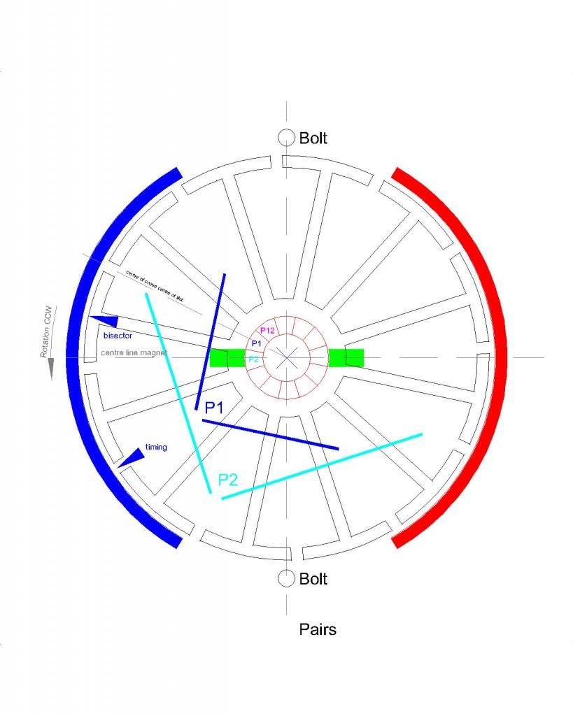 [/img]
Leave a comment:
-
Hi UFO
I can sense a little frustration in your reply, which I can understand, and I can only apologise for the faults in my builds which you have generously offered to debug by replicating my 12 pole motor. I know you have other projects (and life) to attend to, so the offer is gratefully received.
I have looked at the AWG table and the SWG table -
American wire gauge - Wikipedia, the free encyclopedia
Standard wire gauge - Wikipedia, the free encyclopedia
And paste from the wire supplier's website -
0.300mm to 0.710mm Solderable Enamelled Copper Wire
According to the SWG table, 25SWG is 0.508mm.500g 0.5mm Solderable Enamelled Copper Wire
0.500mm 25 SWG Solderable Enamelled Copper Wire (approx: 572 mtrs/kg, 0.0871 ohm/mtr at 20C
According to the AWG table, 24AWG is 0.511mm.
The attached image (below) is the timing for this 3+3 pole all north pairs. P2 is on the brush, P1 is just coming on to the brush. This is my understanding of your comment to retard the timing to be more in repulsion -
Now for the admission from one novice builder to all other novice builders. Speed (rpm) is not the same as Torque.Post #7216. and start playing with the alignment towards more repulse, here on diagram is set at Neutral Fire, right between both stator poles bottom gap....and your needle to adjust timing here is based on the common slot at Pairs Center, where P# are written.
Yes UFO, unfortunately my early posts look confusing and contradictory. Unfortunately I did not understand that speed does not necessarily equate to torque. The 'all-up-weight' of the Beast armature is 876g, the earlier builds would have been slightly under this. This relates to my comment about holding a piece of spinning metal on the kitchen table doing 5 - 6000 rpm. I am not used to the idea of this and it felt like it would lift off with a prop connected. Hence my disappointment when the scooter road test failed.
All my tests to that point focused on volts and amps and revs which are only a partial picture. The only thing that matters is torque, once we have that the other stuff informs us. I had not grasped that.
The in-situ tests for the OEM and Beast with the wheel raised off the floor were not reliable as it turned out the scooter controller cuts out the power on application of the brake. Partial braking applies resistance but then it just cuts. Another misunderstanding of a novice. My second road test took all the electronics out of the equation and that is when I realised there was something more to the equation of testing.
The next phase of my education in front of experienced motor builders was the improvised torque readings. It is crude but it is equal for all motors tested, so the recorded reading for the OEM appears to out-strip the official figures of 0.42Nm 2500 rpm. The actual figures are not important, they are relative and therefore serve to measure one against the other.
My subsequent builds almost don't focus on the figures, it has to perform on the torque rig...then I do the V/A/RPM.
The OEM motor is at this link -
Electric Motor 24 Volt 120 Watt 16T Belt Sprocket ES-01 + ES-05 – PetrolScooter UK
[img] [/img]
OEM from below
[img]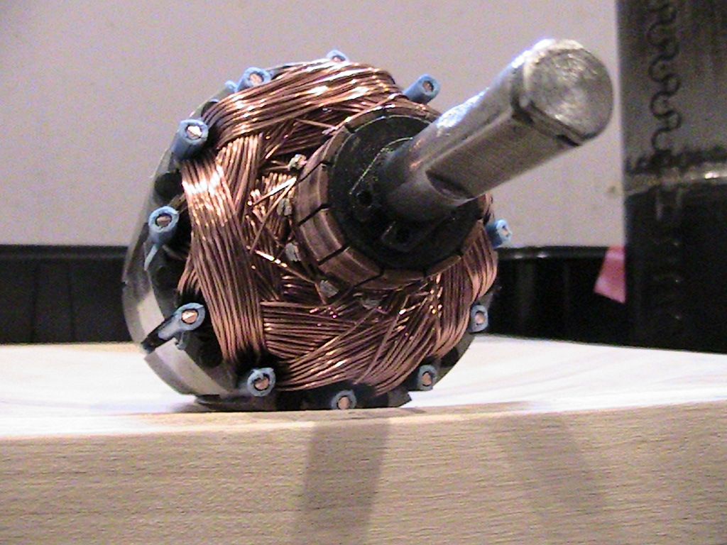 [/img]
Beast #5 from front
[img]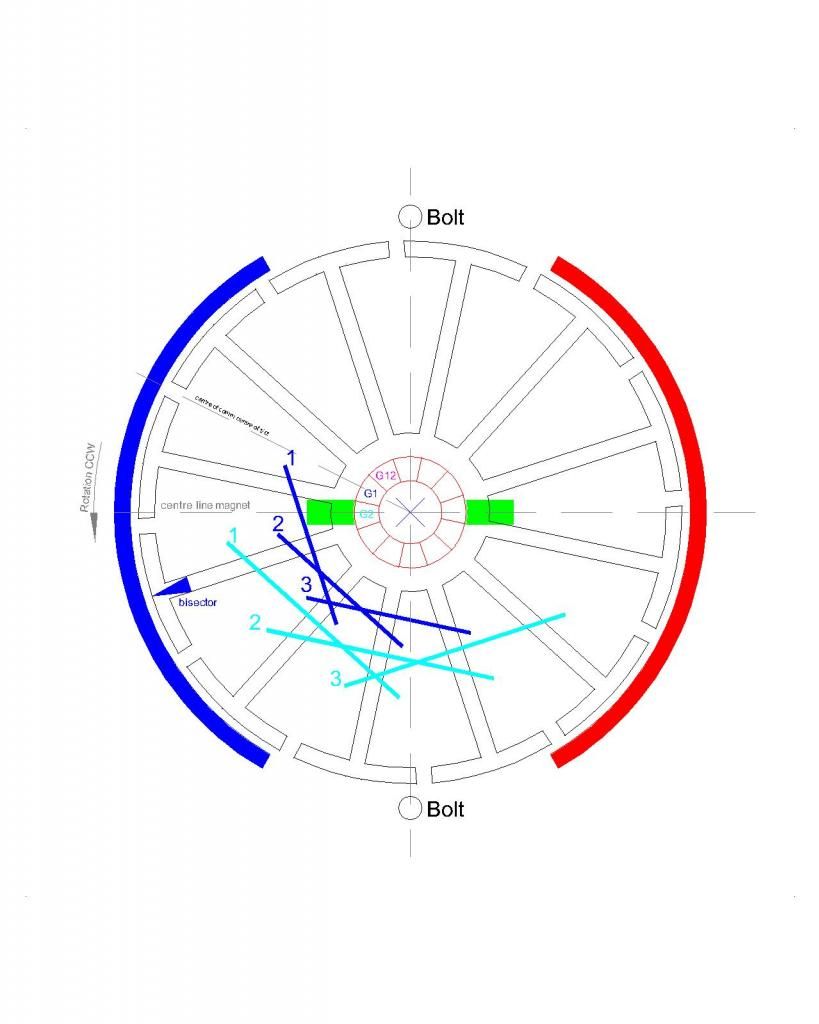 [/img]
TimingLeave a comment:
-
Originally posted by HuntingRoss View Post
Hello Mark,
Sorry about all trouble you are going through...
Could you please show a close up picture, very well Focused,(not blurred) of the Two front armatures OEM and Beast #5, facing camera, just like I have shown on This Post
So, now you are using exactly the same wire gauge as OEM...right?
For some reason, the 0.5 mm Diameter (not square mm cross section area, but just Diameter in mm) corresponds to 24 awg gauge, and exactly is 0.511mm
The next "0.5" is 0.573 and is awg=23.
Based on this chart
The next thing is to go over -again- in the timing settings.
But, one thing I honestly do not understand Mark...is about some previous comments you've made about your very first build, not even a serious strong build, hold with tape...and comparing it versus the OEM:
Post#7129 quoted below:
Tonight I 'got under the bonnet' of the scooter for a look see.
Two sealed lead acid batteries 12v @ 4.5Ah. Total 25.9v on the meter.
First I tested the OEM motor in situ, back wheel off the floor and amp meter connected. A small spike in the amps when the throttle was rolled open and settled to 0.85A.
Stalling this motor is very easy and the stall amps was a massive 8.5A.
Then I pulled out the batteries to connect to my new pride and joy.
With only the amp meter connected the 'beast' took 1.28A @ 5825 rpm.
Removing the amp meter and connecting to volts in and volts out the 'beast' read 23.7v in and 21.3v out @ 6400 rpm within a few revs either side.
Holding on to a piece of spinning metal doing that on the kitchen table was a first for me. And despite the speed it still runs cool.
I think with a prop connected to this motor it would haul something into the air with no trouble...it certainly felt like it was going to lift off.
WHAT a buzz.
happy hunting
mark
Then on Post#7133 You wrote:
Thanks UFO. The motor is still stuck together with tape because the longer bolts haven't arrived...grrr...But the plan is to fit the 'beast' to the scooter and do the tests you mentioned previously for heat build up in the controller and battery wires with full 24v potential. Given the OEM draws 0.9A flat out and the 'beast' draws 1.3A flat out I'm inclined to think heat build up will not be an issue.
Because of the serious amount of torque generated my next plan is to consider fitting it for field testing at 12v only which would appear to be sufficient for the moment and allow everyone to become accustomed to the capability of this motor and it's control. I could either do this by running on one battery or connecting them in parallel and doubling my rated Amp hours to 9Ah.
Despite the OEM motor's lack of torque my daughter has already commented on the backward shove...I hate to think what kind of kick the 'beast' will give.
I've also been trying to source supercaps but the choice is bewildering. Has anyone got advice on the ideal size for this kind of application ?
Best regards
mark
What I do not understand Mark, is how come, just this Two earlier posts you have made, about simple, obvious and plain sight observations/comparisons between OEM and not even a solid build of your Asymmetric Model...denote such a huge difference between both machines..."OEM is very easy to stall...lack of torque", etc...versus a "flying, non stoppable beast"
Then it was the road test, where the 'Beast' failed...and then this new improvised Torque Dyno...where the OEM, all the sudden, has become a 'Beast', unstoppable...of such high torque....and no matter how many adjustments and new builds you have made...Torque on your Asymmetric builds don't even make it to half of the OEM...as a matter of fact they are decreasing performance as you build them...?
We could blame it to inexperience...of a newbie, testing and building Motors for the first time... right?...Well, just common sense Mark...We all know exactly how to just make, with a simple piece of wood, rubber or any other means, a test of both Machines, simple, just like you did on your Two earlier posts mentioned above, and come up with your same, exact, earlier conclusions.
Many have done it here before as well...and with bigger machines...it is written all over.
Let me just say this Mark, I am SURE of ALL my Machines Performance VERSUS the 'OEM' Symmetrical Originals...and they ALL output them completely wiped out in BOTH, Speed and Torque...it is shown on ALL my Videos...plus in ALL other replications of this Machines, except maybe one or two bad builds...or not properly measured parameters.
In conclusion, I can not explain this 'drop-down/decreasing curve' as you build more Asymmetric models...then. it is noticed an 'improved', ascending curve on the OEM, that now have such a High Torque...and stalling it is very hard to achieve.
So, either your very first OEM is not the same as the one you are using now to compare in this latest tests...or you are just not doing it right somewhere along the line of building your Asymmetric ones.
I have exactly this same type of motor spec's (12 Pole, 2 Stators), made in China, the name here is "Torque Master"...when we get the right gauge you are using on your Asymmetric...tell me, and we will convert it to 'AWG'...Then I will wound mine exactly as yours and I will run tests...and I have the 'OEM' 'untouched' as well. I will run simple tests with a PSU, make a video and post it.
I really want to get to the bottom of this Mark...and find exactly what is wrong in your builds...no matter if I have to leave everything am doing now, to go over in detail with you, step by step.
Regards
UfopoliticsLeave a comment:
-
Beast Build #5
The torque test for this motor before I chopped it was -Originally posted by HuntingRoss View Post
160g @ 100mm
So. Moving on to Beast Build #5
0.5mm wire @ 0.0871 ohm / m
12 all north pairs
25 turns 3 poles per coil - 50 turns per pair @ 0.9 ohms
10.33v PSU no load
10.14v @ 1.71A @ 4840 rpm
5 minute run time with some warming of motor
10.19v @ 1.51A @ 4870 rpm
8.04v out
Torque 160g @ 100mm
Stall amps peak 9.0 falling to approx 7.6A
This motor is as tightly packed as it can be and is wound with more care than my others to date.
The timing is better than the #4 build which was slow to accelerate.
It's not clear to me what could be done to improve this motor configuration as it performs worse than the 3 coil group and warms quickly under no load.
I will run this test again with the second set of stators re-fitted and compare results.
markLeave a comment:


Leave a comment: