This forum is preserved as a permanent archive. The community continues at eMedia Press.

Announcement

Collapse
No announcement yet.

My Asymmetric Electrodynamic Machines

Collapse
X
 
  • Filter
  • Time
  • Show
Clear All
new posts

  • replace comm. jumpers?

    Howdy UFO, All,
    The good news, motor will run, but....
    P1 and P8 seem to turn about 2000 rpm if polarity is reversed
    and 24v applied. This is with single-segment active on comm.
    It wont start with 12v. either pol.
    Really surprised at how strongly it 'cogs'. I dont have a pulley
    or coupler on the shaft yet. Hard to turn by hand.
    P15 and P22 dont seem to work at all. I've found sometimes the
    brushes dont make good contact. Ohm-meter shows .3-.4 ohms
    comm. to comm. The PMs seem to be right, testing with a cheapo compas.
    Would it not be a good idea to replace jumpers on comm.? Then
    I could get a better comparison with what others have.
    Also, did HITBY resolve his low RPM prob?
    Appreciate your thots on this, thanx. jw

    Comment


    • 3D Only...

      Originally posted by Cornboy 555 View Post
      Would love to talk about IT any time you wish UFO, so are you saying not related to what you have taught so far, in that the rotor coil projecting N field outwards, say wound CW, would not match, CW wound stator coil as it would project N field outwards and S field inwards, creating attraction rather than repulsion?
      If this is not what you mean ,Could you please elaborate my Friend. Just a simple diagram would be great, and is worth a thousand words to me.
      I have tried to show this differences in a 2D Drawing...but there is "Perspective Confusion" when you look at a 2D Coil trying to "make believe" is in 3D...
      In order to really "see" this Effect...I will have to make it in a 3D CAD-MAYA animated video...and run a Camera around coils so you guys see the differences...trust me...is the only way to understand this...but I find it fascinating.

      I was truely amazed with your video of pulsed fiberglass stator, where the rotor turned without any hot being supplied. I have seen small water pump motors with AC stator and PM rotor do that, but your rotor was wound.

      There is certainly a lot of work to do yet, i agree, and intend, to see it through to Reality

      Thanks UFO,

      Warm Regards Cornboy.
      Yes it is a lot of research to be done here...we are just the Pioneers in this Open Source small Community making replications and R&D on this...when we will get there?...will we ever see a full development of this?

      I don't know my friend...only time will tell.

      Warm regards


      Ufopolitics
      Principles for the Development of a Complete Mind: Study the science of art. Study the art of science. Develop your senses- especially learn how to see. Realize that everything connects to everything else.― Leonardo da Vinci

      Comment


      • Two Segments...

        Originally posted by jeffy39 View Post
        Howdy UFO, All,
        The good news, motor will run, but....
        P1 and P8 seem to turn about 2000 rpm if polarity is reversed
        and 24v applied. This is with single-segment active on comm.
        Hello there Jeffy,

        I believe Machine Alive stated that his Imperial will turn too slow (something very close to yours) when he used just one commutator element...do you remember ?

        It wont start with 12v. either pol.
        Really surprised at how strongly it 'cogs'. I dont have a pulley
        or coupler on the shaft yet. Hard to turn by hand.
        It is very hard to turn it straight from its shaft...

        P15 and P22 dont seem to work at all. I've found sometimes the
        brushes dont make good contact. Ohm-meter shows .3-.4 ohms
        comm. to comm. The PMs seem to be right, testing with a cheapo compas.
        Definitively you have a brush contact problem there... weak or no contact at all.

        Check continuity on each gate, mainly on P15-P22...while rotating Shaft....if it goes open for a few segments...then brush board needs to be aligned because it could be off-centered ...check mating brushes for each gate...if they are in perfect line...

        Push Brushes towards outside while opening spring...and lock them by its own spring (no need to take them out completely)...so you could measure the distance from brush brass housing end and commutator surface...All of them MUST have the SAME distance aprox.

        This Motor when is braking in (new) arcs a lot more since brushes are flat...so getting too close the brass housing will arc on brass ...not good!...so check for arcing black smoke marks on brass housings...

        Would it not be a good idea to replace jumpers on comm.? Then
        I could get a better comparison with what others have.
        Also, did HITBY resolve his low RPM prob?
        Appreciate your thots on this, thanx. jw
        Yes , get the two elements per Pair/Comm (not just one) but like all of Us here...it should work fine once you resolve the mechanical issue.

        Btw...I love that Resistance!!...it must run easy on 12V!

        Hitby was taking apart the whole thing (rewinding it again)...I have not heard from Him since then...
        Regards


        Ufopolitics
        Last edited by Ufopolitics; 04-10-2013, 01:39 AM.
        Principles for the Development of a Complete Mind: Study the science of art. Study the art of science. Develop your senses- especially learn how to see. Realize that everything connects to everything else.― Leonardo da Vinci

        Comment


        • wilco

          Howdy UFO, thanx for reply and suggestions.
          I must have forgotten or missed Mac.Alive's post.
          I noticed some dark spots in middle of comm. segments.
          Could be getting brass-arc. Will have to 'break-it-down'
          to put jumpers in, will inspect brush board carefully.
          Thanx for all, jw

          Comment


          • Originally posted by jeffy39 View Post
            Howdy UFO, thanx for reply and suggestions.
            I must have forgotten or missed Mac.Alive's post.
            I noticed some dark spots in middle of comm. segments.
            Could be getting brass-arc. Will have to 'break-it-down'
            to put jumpers in, will inspect brush board carefully.
            Thanx for all, jw
            Hello,

            Yes, those dark spots between contacting comm elements are normal...(not From brass) even after you widen gaps...
            That happens as coils are leaving contact...energy Tries to "jump back" at where it was...not To the one coming.

            My pleasure


            Ufopolitics
            Principles for the Development of a Complete Mind: Study the science of art. Study the art of science. Develop your senses- especially learn how to see. Realize that everything connects to everything else.― Leonardo da Vinci

            Comment


            • Hmmmm.


              Well UFO, the MAG3 rotor will need to be wound with 36 pairs in a spiral Yes? Can it be wound different?, Star of david?

              Also the last thing i will do to complete motor is wind stators, as they are external and easy to remove and replace, (on purpose) so some time to think about it hey!

              Thanks, Cornboy.

              Comment


              • Not about the "Stars"...

                Originally posted by Cornboy 555 View Post
                Well UFO, the MAG3 rotor will need to be wound with 36 pairs in a spiral Yes? Can it be wound different?, Star of david?

                Also the last thing i will do to complete motor is wind stators, as they are external and easy to remove and replace, (on purpose) so some time to think about it hey!

                Thanks, Cornboy.
                Principles for the Development of a Complete Mind: Study the science of art. Study the art of science. Develop your senses- especially learn how to see. Realize that everything connects to everything else.― Leonardo da Vinci

                Comment


                • Yep.

                  Yeah, got it, Thanks UFO.

                  Regards Friend,

                  Cornboy.

                  Comment


                  • In my last post I was just trying to make a point. And I know that we had discussed it all before so please forgive me for bringing it up again. I know as an end result that we need the control circuits to vary the load. What I was refering to was using what was at hand to prove the concept on a stable load. Now I will gladly let it rest.

                    Comment


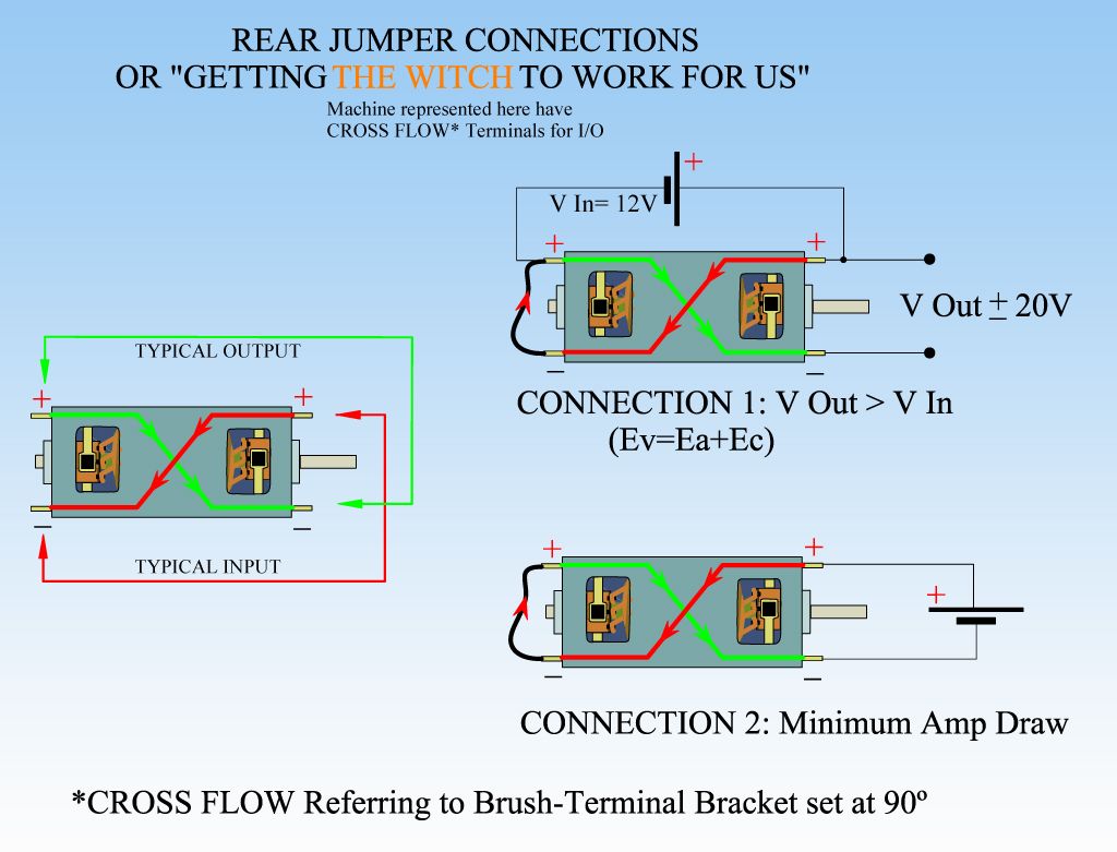
                    • Originally posted by Ufopolitics View Post
                      Hello Ace_Propulsion,

                      Here is the promised Diagram, any questions?...have your Check Book ready/No Credit Cards accepted...

                      [IMG][/IMG]

                      Connection 1 is the same as the one Dana posted...Ec=The Witch
                      Hello UFO,

                      Short the generator?! OMG! I must be silly again(I'm a rookie)

                      Your diagram HELPED ME A LOT. It worked on my 3V, 3 pole Asymm motor(2*AA batt power).The connection wasn't good, so I gonna use carbon(graphite)brushes tomorrow.

                      A few questions:

                      What's the diffrence between these connections? Typical, Connection1 & 2
                      In my opinion Typical is used as a COP>1 generator in "Face to face connection mode"
                      Connection 1 gets 20V, COP=1.8?? Is that correct??

                      And what about Connection 2:minimum amp draw. Output mechanical COP>1?

                      P.S:I got a problem in this forum on yesterday. Every time when I tried to log in, it kept jumped to index page(http://www.energeticforum.com/) and I can't get logged in.(You could see this reply on yesterday if there's no problem. Sorry for that!)

                      Cheers

                      Comment


                      • Originally posted by Ufopolitics View Post

                        Hitby was taking apart the whole thing (rewinding it again)...I have not heard from Him since then...
                        UFO,


                        https://www.dropbox.com/s/ribkktoqtaffabl/SAM_0091.JPG that did work (as you knew it would) You know your tech !!!

                        After several tests with that adjustment we went with the rewinding bit, currently we are half way done with the rewind https://www.dropbox.com/s/ra3yvkeddiqyrfx/SAM_0095.JPG

                        Hope to report more soon.

                        Warm regards

                        Hitby13kw

                        Comment


                        • brush plate out of kilter

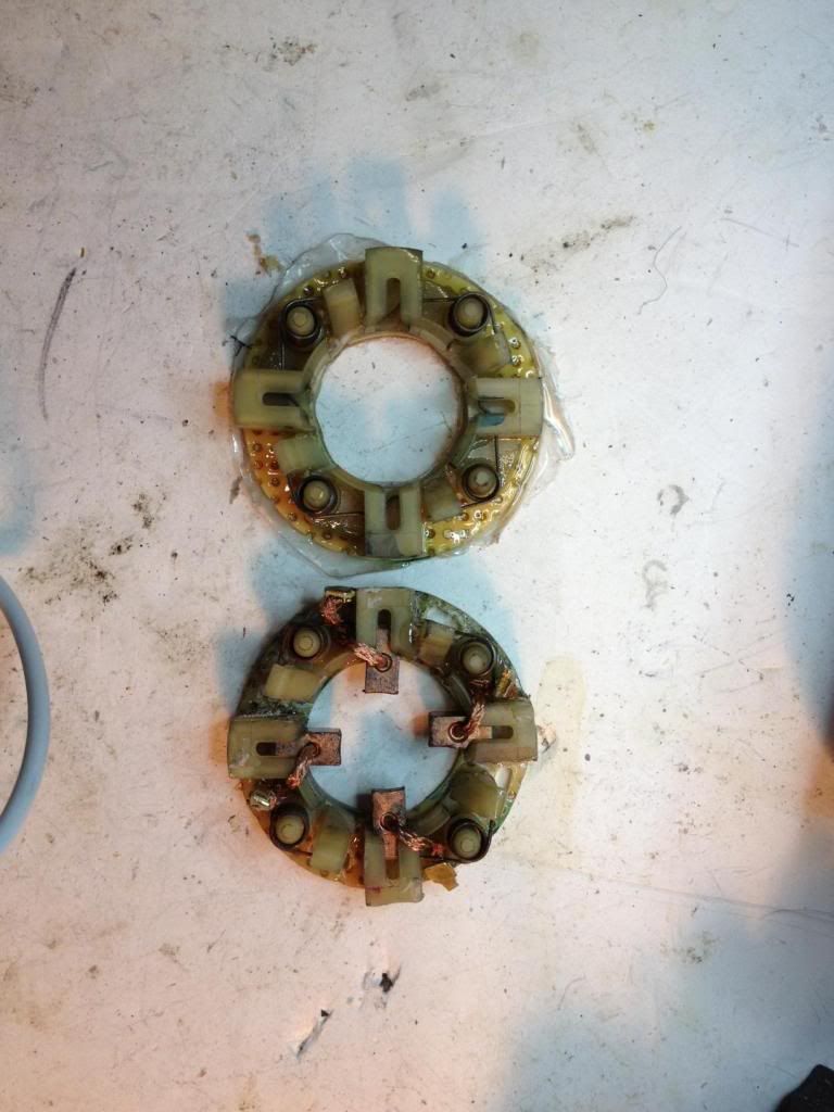
                          an itsy-bit. Kind of a small motor for 8 brushes maybe. Hard to get any kind of precision going. All eyeball, as you struggle with super glue on the finger tips. Coated with epoxy too and those babies aren't coming off for nobody. So here is a pic.


                          How do they look? They seem about 5 degrees here and there, looks like one will hit a segment about a mil before the opposite brush. Should I grind off the mounting plate and try again? Maybe just the lower one, it's the worst.
                          Up, Up and Away

                          Comment


                          • 550 Body Motor Dual Pentagon Winding

                            Hello to All,


                            DUAL PENTAGONS/550 MOTOR BODY TESTING - YouTube


                            Enjoy


                            Ufopolitics
                            Principles for the Development of a Complete Mind: Study the science of art. Study the art of science. Develop your senses- especially learn how to see. Realize that everything connects to everything else.― Leonardo da Vinci

                            Comment


                            • Impressive UFO, Impressive.

                              Thanks Cornboy.

                              Comment


                              • Originally posted by Ufopolitics View Post
                                Hello Ace_Propulsion,

                                Here is the promised Diagram, any questions?...have your Check Book ready/No Credit Cards accepted...

                                [IMG][/IMG]

                                Connection 1 is the same as the one Dana posted...Ec=The Witch
                                Hello UFO,

                                This is my understanding

                                Connection 1:voltage multified 1.8 but due to energy loss to run the motor. The COP can't always higher than 1. Two condition should be met(1:low mechanical friction. 2:Adequate load(neither too high nor too low))
                                Connection 2:Powerful energy-saving motor, mechanical COP=1.8

                                The fun stuff : If you use connection 1 to charge a battery. Then swap batteries. Repeat several times. You'll get both bateries charged.

                                Regards

                                Comment

                                Working...
                                X