
RC modelling
Planning some tesla motor redesigns of RC cars and aircraft electric motor powerplants. I am betting on 50% increase in range/time aloft and will be able to test it out and prove performance against the stock power plant. I have bought two car kits and am going out for my model aircraft next.
-
Dad Hav's magent trick
Just repaired a cracked magnet with this trick, building up a Plastic Weld (This stuff seems harder than epoxy when it dries!) bridge on the exposed end to hold it down on my mini-AC generator rotor. easy peasy cracked end slipped right in with the extra magnet on top!Originally posted by DadHav View Post
Thanks JohnLast edited by sampojo; 07-31-2015, 05:47 PM.Leave a comment:
-
GChilders and Ufo teaming up on his Imperials
PM let me know that having a tough slough of it. Garry got 3 Imperial Ufo kits and they all had unmagetized stators!!! He ended up buying some used ones for parts. Guess it was easier than dealing with Imperial?
Good luck Garry!Leave a comment:
-
Re: Grinding Magnets, temps
Dadhav, Roger that harmful stuff, magetic dust, I am sure once in the lungs, there is no coming out, strange affinity to blood
Looked up magnets on wikipedia, found that neo's are a little more sensitive to heat then ceramics. Neos had a critical temp around 400def(F I think?), while ceramics 900... Always worried about my motors getting too hot around 130-150deg and losing magnetism, but looks like you could fry an egg on them without worrying, as long as the wiring can take the temps... Guess the critical component would be the magnet wire insulation. Epoxy, I use it to hold down the wires, seems can take 200F easy...Leave a comment:
-
Hello Sam,
It sounds like you're trying to put poles together using the same polarity magnets. This can be really difficult as you say but there is an easy trick. If you can get two of them close enough together to slide a third over the two they will stay side by side (usually). The top magnet naturally needs to go over the magnets where you want them to touch. Careful grinding the magnets, the dust is harmful and vibration as well heat from the grinder can weaken the magnets. I was wondering the same thing about the posts here and on the other guy's forum. I was hoping to hear some encouraging news. Good luck.
JohnLeave a comment:
-
Update
Hi Jeff, yeah kinda eerie. I was hoping to see GChilders next project he wanted to do. I am working on building a small AC generator to be driven by my GM unipolar motors. I will only need to put out a few amps at 12v trying to get about 3600rpm on it. I had to use neo magnets which have been incredible difficult to mount as needed... 6 more to mount and now I need to grind at least one down to fit
Additional info: Redesign of the AC motor required a new rotor, had to reconstruct it once already, faulty design. Progress is slow. I had a great day last week before vacation, actually mounted 3 magnets.
I have a large Baldor motor I will be winding hopefully in the not-to-distant future also...
You have anything going?Last edited by sampojo; 07-16-2015, 01:06 PM.Leave a comment:
-
Hello out there!
Hello! Is this thread now dead? Where'd everybody go?Leave a comment:
-
Originally posted by HuntingRoss View Post
Exactly Mark...so all you need to do is to "step" on that accelerator pedal...and ICE will distribute the timing properly without choking because over flooding in gas, or blowing a cylinder through the head.
A Symmetrical Motor can only take certain amount of "gas"...after that limit it burns crispy and well done...
An Asymmetrical Motor can take MUCH more gas feeding...but there would always be a limit for it to go over temp excess and melt down...
An Asymm Stepped Sync Controlled Motor could take infinite gas supply...just like an ICE does.
Cheers
UfopoliticsLeave a comment:
-
Thanks UFO
The mechanical analogy to an ICE machine makes it simpler because the rotor itself can hold the timing points for firing just like the distributor. Simple is good.
Happy Hunting
markLeave a comment:
-
Hello Mark,Originally posted by HuntingRoss View Post
Garry brought that question over (path of least resistance)...and he is right, up to a certain point though...
I believe He was referring to -exactly- that nanosecond when brush starts touching commutator segment (very first edge to edge)...However, after that time, brush engages with two segments in an approx ratio of 80-20%, 70-30%, 60-40%, to 50-50% (half point)...to then start to 'leave' at 40-50, 30-70, 20-80...and so on.
I believe, that from even 80-20% the transmission of electricity is practically the same to both circuits, and if there are some differences...they would be very, extremely insignificant.
I would say that it would not be exactly a 'soft' bell curve at full engagement, but a very small straight line that will last for the length/time of contact...while the ascending time period would not contain much slope...but almost a very straight up, almost vertical line...While the "transition" from one to two commutator segments would display a slight drop down, but never reaching zero levels.
Last edited by Ufopolitics; 06-13-2015, 01:22 PM.Leave a comment:
-
Sweet spot versus super sweet spot
You are right Ufo. The AN-1 amp draw is a 40% drop!!! Pretty huge. Definitely had a sweet spot just not a "super sweet spot". Thinking about a test Rig as you suggest to allow turning with motor operation. That would give me better control and more granularity in order to find that "SSP"
 . I estimate that I was moving the endplates 6-12 deg per adjustment. A nice old-fashioned panel and meter would be better to take amperage data then a digital VOM, judging by the way it fluctuates.
Last edited by sampojo; 06-10-2015, 01:18 PM.
. I estimate that I was moving the endplates 6-12 deg per adjustment. A nice old-fashioned panel and meter would be better to take amperage data then a digital VOM, judging by the way it fluctuates.
Last edited by sampojo; 06-10-2015, 01:18 PM.Leave a comment:
-
AN-1...finding sweet spot.
Hey Sam,Originally posted by sampojo View Post
Yes, quite a difference Huh?
Garry adjusted timing more towards Attraction Mode...meaning moving Motor Brushes according to Rotation direction, in order that P1 starts firing closer to South Bisector. I would try to start from the "Neutral" position or centering P1 right at Stators Gap...then start slowly moving it towards rotation.Garry, can you post a timing diagram showing the angle of endplate rotation to hit the sweet spot, exactly how much different from the start position on the AN-1 diagram? Is it in your videos?
To accomplish that task, something like what I did in my Pentagon Y diagram in my post #7855
Well, that is already some pretty big improvement so far...if we compare with what you wrote on the previous test with Dual Penta...:Starting some testing now...
First look, no sweet spot like we hoped, tested 8 positions, best was 31,000rpm @12.3v/0.7A
You will eventually find that sweet spot...BUT, Remember that such low amperage...like 0.08 or 0.09 amps...is the Total Operating Amperage that your armature is using to spin...PLUS is set to Attract Mode...which is weaker than Repulse...so, I would NOT expect such a High Torque/Power at those amp levels my friend.Originally posted by sampojo View Post
Also note on Garry's chart below the RPM's motor was developing when it was consuming 0.085 Amps at 12 Volts as well...:
[IMG]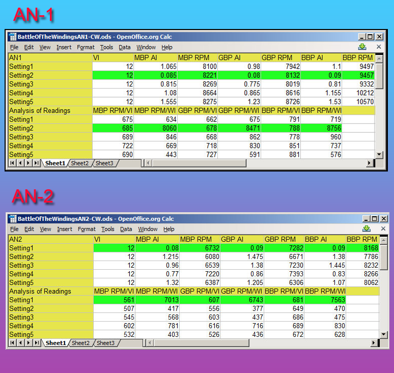 [/IMG]
It was below 10,000 RPM's...while you are making it "dance" at 30,000 spins per minute...
Since Garry did not write any decimal values in Volts readings above...I would try to maintain supply around exactly 12.00 V or lower...like 11.85 or so until you get below 10,000 RPM's...it also have to do with Battery operating amps at that point of testing.
It also helps if Garry give you a resistance value from each Pair...then you make a comparison reading as well.
The closer you get to Garry's set up...the faster you will find that SP (Sweet Spot)
Good luck in your search and tests...

Ufopolitics
EDIT 1: After you find "Nemo"......it would be great to make a Pulse Feeding Test...some small 12V Oscillator, like with a 555 Timer... Last edited by Ufopolitics; 06-10-2015, 12:01 PM.
Leave a comment:
-
AN-1 vs original RS homopolar
Ufo, Quite the difference here. Totally missed this when it happened. Always assumed AN-1 was the same as your first homopolar radio shack creations.
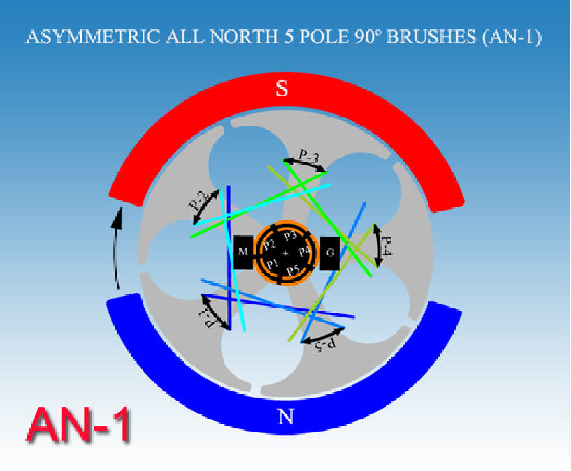
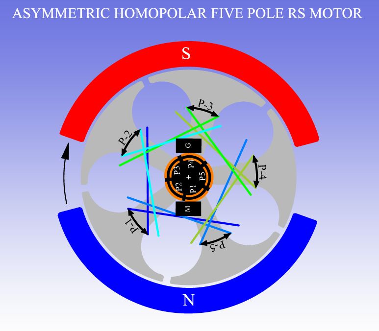
Garry, can you post a timing diagram showing the angle of endplate rotation to hit the sweet spot, exactly how much different from the start position on the AN-1 diagram? Is it in your videos?
To accomplish that task, something like what I did in my Pentagon Y diagram in my post #7855
Starting some testing now...
First look, no sweet spot like we hoped, tested 8 positions, best was 31,000rpm @12.3v/0.7ALast edited by sampojo; 06-10-2015, 05:04 AM.Leave a comment:

Leave a comment: