This forum is preserved as a permanent archive. The community continues at eMedia Press.

Announcement

Collapse
No announcement yet.

My Asymmetric Electrodynamic Machines

Collapse
X
 
  • Filter
  • Time
  • Show
Clear All
new posts

  • Five Steps Advance Angles Video...

    [VIDEO]https://www.youtube.com/watch?v=st6ygKoAzYY[/VIDEO]

    IMPERIAL FIVE STEPS ADVANCING ANGLES
    Last edited by Ufopolitics; 05-31-2015, 03:28 PM.
    Principles for the Development of a Complete Mind: Study the science of art. Study the art of science. Develop your senses- especially learn how to see. Realize that everything connects to everything else.― Leonardo da Vinci

    Comment


    • Five Steps in Frames

      STEP 1

      [IMG][/IMG]

      STEP 2

      [IMG][/IMG]

      STEP 3

      [IMG][/IMG]

      STEP 4

      [IMG][/IMG]

      STEP 5

      [IMG][/IMG]

      Ufopolitics
      Principles for the Development of a Complete Mind: Study the science of art. Study the art of science. Develop your senses- especially learn how to see. Realize that everything connects to everything else.― Leonardo da Vinci

      Comment


      • There must be a collective sigh of relief around the forum to see that we now agree.

        Happy Hunting

        mark

        Comment


        • Imperiall P56 Rotor Spec's

          Hello to All,

          @Mark Ross: Yes, if you say so, that is great Mark.

          Now, keeping on...below are the Real Rotor Commutator Measurements Spec's from Imperial P 56:

          [IMG][/IMG]

          I believe this measurements could help us to understand the ratios from switching and magnetic interactions.

          [IMG]
          Last edited by Ufopolitics; 06-01-2015, 04:33 PM.
          Principles for the Development of a Complete Mind: Study the science of art. Study the art of science. Develop your senses- especially learn how to see. Realize that everything connects to everything else.― Leonardo da Vinci

          Comment


          • So the magnetic interaction 'oscillates' between the ON and OFF angle...So is there frequency and harmonics here...Curious.

            Happy Hunting

            mark

            Comment


            • Originally posted by HuntingRoss View Post
              So the magnetic interaction 'oscillates' between the ON and OFF angle...So is there frequency and harmonics here...Curious.

              Happy Hunting

              mark
              Exactly Mark, and this precise oscillations could be read clearly from the output gates with a Scope (since no interference, no reversal, one single flow direction) when output is directly sync with Input.

              The All North, single flow, no reversal Method, when running for a short while the whole Rotor core becomes all North polarized on outer circumference projecting towards stators...and South near shaft (inner), So all we are doing is 'pulsing' stronger north sections of core at the motoring energized coils interacting with stators. Where this 'pulsing' actually becomes a short timed sweep from On-Off bisectors.

              I am glad you decided to open your own thread related to the single commutator development, and I wish you great luck with future experiments.


              Sincerely


              Ufopolitics
              Principles for the Development of a Complete Mind: Study the science of art. Study the art of science. Develop your senses- especially learn how to see. Realize that everything connects to everything else.― Leonardo da Vinci

              Comment


              • Originally posted by Ufopolitics View Post
                Where this 'pulsing' actually becomes a short timed sweep from On-Off bisectors.
                So it was stated recently that the output from these motors is AC.

                My appraisal of the output was pulsed DC and your comment seems to suggest there is 'snap on' and 'snap off' for the pulse.

                I wish I had a nifty scope to play with...maybe Santa will be good this year.

                Happy Hunting

                mark

                Comment


                • Originally posted by HuntingRoss View Post
                  So it was stated recently that the output from these motors is AC.
                  Don't know who stated that it was AC out...?

                  My appraisal of the output was pulsed DC and your comment seems to suggest there is 'snap on' and 'snap off' for the pulse.
                  It is a pulsed DC, however, it is not an organized or 'clean' square wave output as you get in a solid state PWM oscillator...However, it can charge Caps...Supercaps...or batteries without being filtered.

                  I wish I had a nifty scope to play with...maybe Santa will be good this year.

                  Happy Hunting

                  mark
                  Maybe...if you behave well...


                  Ufopolitics
                  Last edited by Ufopolitics; 06-02-2015, 07:27 PM.
                  Principles for the Development of a Complete Mind: Study the science of art. Study the art of science. Develop your senses- especially learn how to see. Realize that everything connects to everything else.― Leonardo da Vinci

                  Comment


                  • the other set of Motor Brushes would NOT be aligned inline[/IMG]

                    The initial set up above shows M1 Brushes, fully aligning P1 (blueP16 & P17P15...[/IMG]

                    When LEFT M1 Brushes start firing P28P16-P17..and we can see the Red Arrow showing the Higher Attract Interaction Angle.

                    I know this set up looks very "odd" and "Asymmetric"...since the propulsion forces does not seem to be balanced or "compensated" at both ends of the shaft...but they are...it is just we are looking at two different interactions here...Attract and Repulse...which are completely opposed to each others, however, they are utilized in both sides of shaft simultaneously.

                    When shaft keeps rotating we have following Diagram:

                    [IMG][/IMG]

                    We notice M1 is now centered-aligned between P1 & P28...while M2 is fully aligned with P15...and P17 is OFF now.

                    Notice the different Repulse-Attract Interaction Angles, how they have "contracted".

                    Now...if We move M1 in order to align with M2, then we will have Higher Attract percentage at both sides symmetrically...

                    But, if we move M2 to align with M1...then we will be on Max Repulse on both sides.

                    And, of course this set up will definitively affect Output Gates...But mainly, the overall Motor Performance.

                    Hope you understand all this.

                    If we all remember about the way Internal Combustion Engines (ICE) Cycle related to timing the "firing cylinders"...we realize they do it "alternatively", meaning, one cylinder is fired while other one is at "exhaust" or two piston fire at a time max, depending on total number of cylinders along crankshaft...

                    I am trying to set a delay between firing orders here...but related to mixing magnetic interactions of different kind, and at different times...breaking the Symmetry even more...


                    Regards to All


                    Ufopolitics
                    Last edited by Ufopolitics; 06-03-2015, 07:09 PM.
                    Principles for the Development of a Complete Mind: Study the science of art. Study the art of science. Develop your senses- especially learn how to see. Realize that everything connects to everything else.― Leonardo da Vinci

                    Comment


                    • Looks fine as an idea.

                      I'm wondering if it affects the search for the perfect timing which theoretically seems to 'fit' well with a 'balanced' rotor rather than an 'asymmetrically' loaded rotor.

                      You have me wondering what happens if you wind one side 'pairs' and the other side 'groups'...I might make that a quick and dirty build one rainy day.

                      Happy Hunting

                      mark

                      Comment


                      • Originally posted by HuntingRoss View Post
                        Looks fine as an idea.

                        I'm wondering if it affects the search for the perfect timing which theoretically seems to 'fit' well with a 'balanced' rotor rather than an 'asymmetrically' loaded rotor.
                        You have me wondering what happens if you wind one side 'pairs' and the other side 'groups'...I might make that a quick and dirty build one rainy day.

                        Happy Hunting

                        mark
                        You could do it in the SC as well...making wider North's or South's poles, then leaving wider gaps to collect more at output...too bad you only have one commutator...and as a matter of fact...the way you have the four brushes at closed angles...you could switch to make it happen.

                        Oh!...and it is not going to be just an 'idea' after I finish winding Imperial All North Pairs...


                        Keep Hunting


                        Ufopolitics
                        Principles for the Development of a Complete Mind: Study the science of art. Study the art of science. Develop your senses- especially learn how to see. Realize that everything connects to everything else.― Leonardo da Vinci

                        Comment


                        • Originally posted by Ufopolitics View Post
                          You could do it in the SC as well...making wider North's or South's poles, then leaving wider gaps to collect more at output...too bad you only have one commutator...and as a matter of fact...the way you have the four brushes at closed angles...you could switch to make it happen.

                          Oh!...and it is not going to be just an 'idea' after I finish winding Imperial All North Pairs...
                          I hadn't thought about that...using the bent angle of my SC brushes to try the same thing...damn clever idea.

                          I was thinking about trying the mixed pairs and groups...Hmm...more projects than I can shake a stick at.

                          I wasn't suggesting it was going to remain as an idea. There would be little point in that.

                          Is there any chance this wind could be compared to the 'normal asymm' wind in a Prony test to see which Asymm Imperial comes out on top ?

                          Happy Hunting

                          mark

                          Comment


                          • Originally posted by HuntingRoss View Post
                            I hadn't thought about that...using the bent angle of my SC brushes to try the same thing...damn clever idea.

                            I was thinking about trying the mixed pairs and groups...Hmm...more projects than I can shake a stick at.

                            I wasn't suggesting it was going to remain as an idea. There would be little point in that.

                            Is there any chance this wind could be compared to the 'normal asymm' wind in a Prony test to see which Asymm Imperial comes out on top ?

                            Happy Hunting

                            mark

                            Make sure to check on CAD before real fire..
                            Principles for the Development of a Complete Mind: Study the science of art. Study the art of science. Develop your senses- especially learn how to see. Realize that everything connects to everything else.― Leonardo da Vinci

                            Comment


                            • Make a new plan, Stan: Looking at Radio Shack hobby motors again

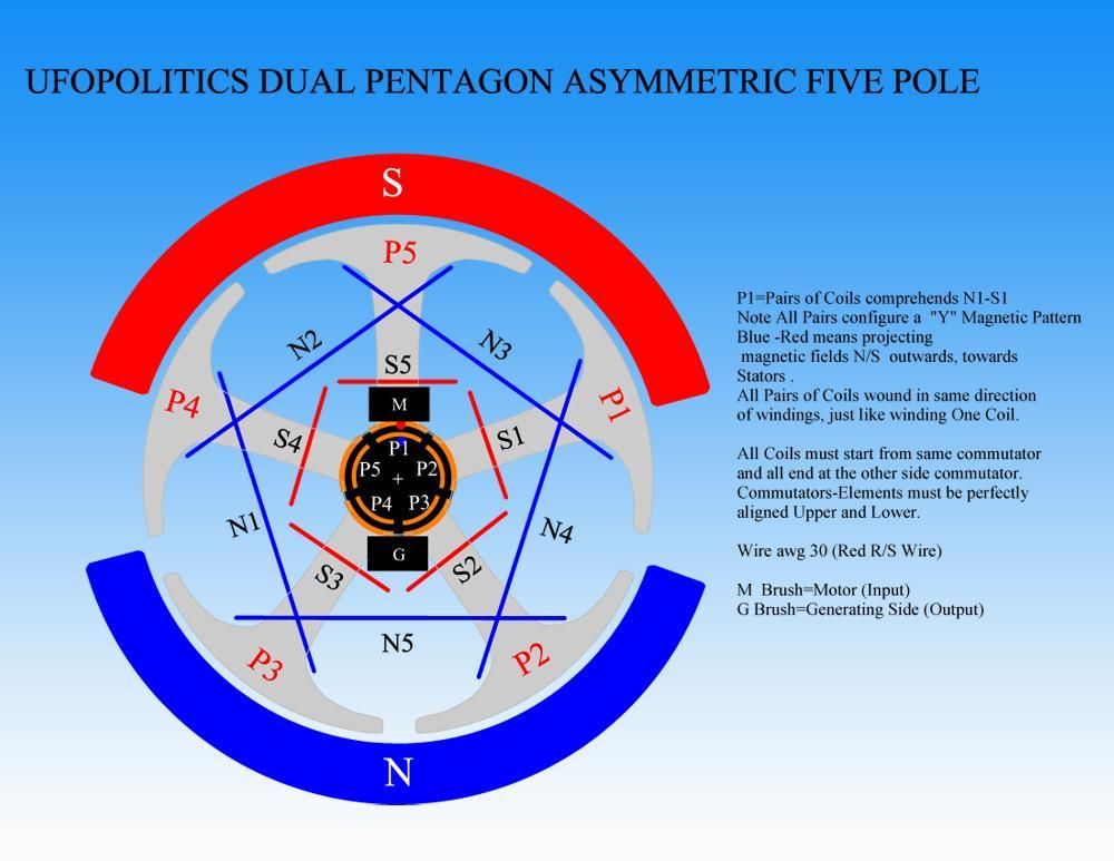
                              I am considering reproducing the AN-1 or AN-2 winding to look for GChilders low amp readings. I got out the Ufo Pentagon Y N-S Winding motor I built to get some baseline data. I was a little disappointed at the time in the construction and had no good way to secure the endplates. It was drawing over 1.5A and was running pretty hot to the touch, but in reality was getting to only about 120degF. I never tried to tune it. Using a 12v battery, I got about 24000rpm out of it on the diagram settings. Here is Ufo's winding diagram.


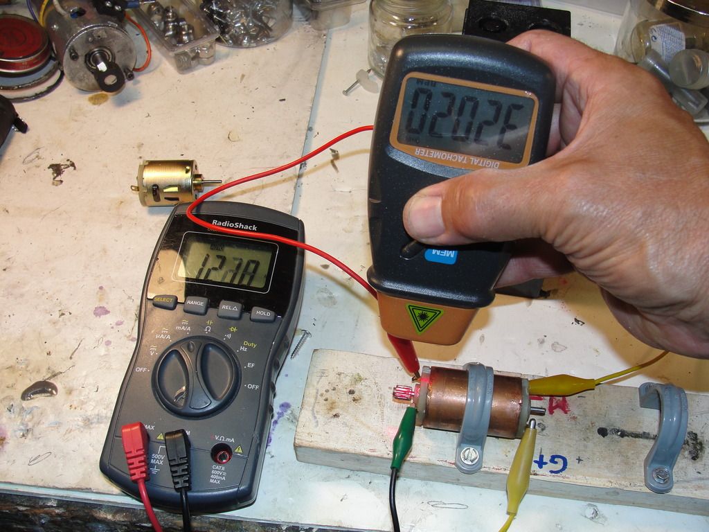
                              After playing with it a little bit, I found it hangs together well and tunes easily, a good platform for the unipolar experiment. I found a nice sweet spot about 20deg off the diagram setting and got some pretty astounding results, but not so much of course on the amp side, although lower. On 12v, I got the amps down to around 1.25A and the rpm up over 30,000. Here is the pic (rpm reading is upside down):


                              I will extract the optimum setting off the motor and repost it on the above diagram. Thought you might like to see and hear this puppy run, so I did a video. Sorry didn't notice the dim lighting on the rpm gauge in the camera.


                              Sam's Pentagon Y Radio Shack after tuning

                              So now for a unipolar wind on a new rotor!! My thanks for all the analysis on my quad 10-pole, but I am going to post pone winding that, as that would probably take a couple man-days of effort, and time is a precious commodity for everyone. The quickest way to a low amperage reading with the highest probabilty of success would be to try to reproduce Garry's windings exactly. I only need a few hours there hopefully.

                              So as I think about the design for this motor, I have decided to use the normal approach and go for a finer gauge than what is on the standard edison design, so that would be 32ga. Until I get the tuning effect sweet spot, I will design the motor to run as if it was on the normal amperage range. I think it is running a little hotter than I would like now so I will look to increase the the resistance about 20%. I have to look at the ft/ohm (6?) value for 32ga, but think I can put 12' of wire per coil, except that could be 2 ohms, maybe a little high. Could possibly stay on the 30ga, as there is around 30% unfilled area of the rotor on the stock motor I could fill there, and it comes to about 9' per coil there. Hmm, 30ga might work...

                              @Gchilders: Could you post the gauge and wire length you used for the Goldmine motors? TIA

                              If reproduction of the low amp readings becomes guaranteed, and heating in the corresponding motors fulfill expectations, i.e. they run stone-cold, well then, that opens a design possibility where these little motors could be designed a little like the forklift motors, say a much lower coil resistance around .1 ohm, not 1 ohm, if my logic is correct. This motor would of course be some kind of monster!!!! RPM??? Motor stresses could be incredible. 12v might be too much... Or never run it unloaded !!

                              If I can reliably get the low amp reading, my next move may be to wind my Baldor 56 frame motor 20 pole exactly like a Goldmine or RS 5-pole AN-1 or 2 winding motor to see what the amp draw looks like there. I think this design would be very seviceable in the real world. Once achieved, I would then look toward other pole winding arrangements...

                              Carry on, Tesla soldiers!


                              EDIT PS: in reply to Ufo below, I think I need a few drops of epoxy around my bearing housing, its fit is too sloppy in the endplate seat I made and it can come very loose, and I think mostly responsible for the pulsing oscillation of the rpms, along with a less than perfect balance in the rotor...
                              Last edited by sampojo; 06-05-2015, 07:02 PM.
                              Up, Up and Away

                              Comment


                              • Originally posted by sampojo View Post
                                I am considering reproducing the AN-1 or AN-2 winding to look for GChilders low amp readings. I got out the Ufo Pentagon Y N-S Winding motor I built to get some baseline data. I was a little disappointed at the time in the construction and had no good way to secure the endplates. It was drawing over 1.5A and was running pretty hot to the touch, but in reality was getting to only about 120degF. I never tried to tune it. Using a 12v battery, I got about 24000rpm out of it on the diagram settings.

                                After playing with it a little bit, I found it hangs together well and tunes easily, a good platform for the unipolar experiment. I found a nice sweet spot about 20deg off the diagram setting and got some pretty astounding results, but not so much of course on the amp side, although lower. On 12v, I got the amps down to around 1.25A and the rpm up over 30,000. Here is the pic (rpm reading is upside down):


                                I will extract the optimum setting off the motor and repost it on the above diagram. Thought you might like to see and hear this puppy run, so I did a video. Sorry didn't notice the dim lighting on the rpm gauge in the camera.

                                Sam's Pentagon Y Radio Shack after tuning

                                So now for a unipolar wind on a new rotor!! My thanks for all the analysis on my quad 10-pole, but I am going to post pone winding that, as that would probably take a couple man-days of effort, and time is a precious commodity for everyone. The quickest way to a low amperage reading with the highest probabilty of success would be to try to reproduce Garry's windings exactly. I only need a few hours there hopefully.

                                So as I think about the design for this motor, I have decided to use the normal approach and go for a finer gauge than what is on the standard edison design, so that would be 32ga. Until I get the tuning effect sweet spot, I will design the motor to run as if it was on the normal amperage range. I think it is running a little hotter than I would like now so I will look to increase the the resistance about 20%. I have to look at the ft/ohm (6?) value for 32ga, but think I can put 12' of wire per coil, except that could be 2 ohms, maybe a little high. Could possibly stay on the 30ga, as there is around 30% unfilled area of the rotor on the stock motor I could fill there, and it comes to about 9' per coil there. Hmm, 30ga might work...

                                If reproduction of the low amp readings becomes guaranteed, and heating in the corresponding motors fulfill expectations, i.e. they run stone-cold, well then, that opens a design possibility where these little motors could be designed a little like the forklift motors, say a much lower coil resistance around .1 ohm, not 1 ohm, if my logic is correct. This motor would of course be some kind of monster!!!! RPM??? Motor stresses could be incredible. 12v might be too much... Or never run it unloaded !!

                                If I can reliably get the low amp reading, my next move may be to wind my Baldor 56 frame motor 20 pole exactly like a Goldmine or RS 5-pole AN-1 or 2 winding motor to see what the amp draw looks like there. I think this design would be very seviceable in the real world. Once achieved, I would then look toward other pole winding arrangements...

                                Carry on, Tesla soldiers!

                                Nice work Sam!

                                One thing that I want to tell you primarily, and therefore, very important.

                                Replay that video again...and concentrate on the humming sound of motor...until you detect the "Sound Pattern" is making...or better expressing it...the sound pattern is repeating.

                                Notice a High then a Low pitch humming?...repeating itself?

                                If you get a mic and some sound editing software, you will be able to "see" this pattern.

                                Your motor is not developing a full RPM (yeah, I know, even going at those speeds!) because there is 'something' stopping it to complete its ascending cycle...so it constantly 'restarts' over and over.

                                It could be your timing...and since it is a N-S Config is hard to tell...where an All North Machine is easier, just tracing one magnetic pole.

                                Any electric motor is supposed to start in an ascending mode till reaching its max full speed...then it will seat there steadily...so it would be a firm and fixed "humming"...not going back and forth like is doing here.

                                This could be a reason why the amps and output voltage remain up-down, up down...etc.

                                Try to play with timing a bit more, retard it and then advance it...checking the Rotor Bisectors not passing your stator Bisectors.

                                Keep listening to the sound at all times during adjustment...it would tell you if you are going in the wrong direction by shortening the up-down humming time frequencies.

                                Also watch RPM's when start increasing even more...it would seem is gonna take off ground...I have taken this little things over 42,000 RPM's but, it was with the AN1.

                                Now related to the rest...I am looking forward to see your AN1 Replication working...so the differences could be seen then finally established.

                                Related to wire gauge...

                                Keep in mind that finer wire will do reduce amps...but the price is a demand for Higher Voltage.

                                Also finer wire will generate weaker magnetic fields.

                                Although there is a 'limit' a point that you must find where fine wire works perfectly well when you balance everything there.

                                On Forklift Motors, as well as Newer Golf Carts, and some late EV's...a very low resistance heavier wire is very tempting...and, yes, the final output is unpredictable until is done and tested. The advantage we all have with asymmetric is that they are constantly disconnecting, so no time to heat or burn them at very high speeds, and of course, depending on number of total independent circuits in rotor. Meaning, the more the better.


                                Looking forward to see next tests!


                                Regards


                                Ufopolitics
                                Last edited by Ufopolitics; 06-05-2015, 03:37 PM.
                                Principles for the Development of a Complete Mind: Study the science of art. Study the art of science. Develop your senses- especially learn how to see. Realize that everything connects to everything else.― Leonardo da Vinci

                                Comment

                                Working...
                                X