-
-
In this scenario, we can program the chip to simulate this action with the pulsout command;Originally posted by ldissing View Post
Let's say pin 4 equals the biasing of Q1;
pulsout 4, 800 (which means, send a pulse (5v) signal out pin 4 for 800 ms)
pulsout 4, 600
pulsout 4, 400
pulsout 4, 200
pulsout 4, 100
Obviously this would not be a nice declining slope in the circuit Leroy illustrates but it would come close.
Just my thought's
Bit'sComment
-
JBs comments
JB commented in one post, that perhaps the transformer version (or maybe he said coil" was the "correct" one. I have not been able to find it. Does anybody have this information?
Thank you in advance,
LeroyComment
-
For smoother results you could use
FREQOUT Pin, Duration, Freq1 {, Freq2} The freak out command. LOL
No seriously you could use FREQOUT coupled with a timer. Start at a low frequency and raise the frequency from there. The faster the frequency the less current will get through. I know it works with the stamp chip I am using and so far most code seems compatible to the PIC.
Might work who knows.I VAR Byte
I = 0
DO
I = (I +1)
FREQOUT 4,(I),(I)
LOOP UNTIL (I = 10)
MattComment
-
You are an elusive fellow...wondered when you would pop back up. In your new house yet?Originally posted by Matthew Jones View Post
LeroyComment
-
Ya finally unpacked to. I think unpacking my junk was harder than building the house. LOL
I've been following along the whole time.
MattComment
-
It's not a 'true' negistor
Yes JB,Originally posted by John_Bedini View Post
This was not a real 'true' negistor.
Current can flow in opposite direction through the semiconductor,
but its not a real 'TRUE' negistor.
Anyway I cleared one misunderstanding and corrected my way to ' Negistor'Comment
-
@Matt: Looking forward to anything you have to say! Glad your move is over...mine is just starting, don't know how long it will take to sell this house in this market....Originally posted by Matthew Jones View Post
LeroyComment
-
JANGYD,Originally posted by JANGYD View Post
I'd be interested to hear your findings on the Negistor. I've done some research in this area, but just to dense to figure it out I guess. Any input is appreciated.
Thanks,
LeroyComment
-
I believe you are looking at the same diagram based on your description. I don't know exactly how that is working based on the connections. When Q1 is on (SG3524 pins 13,14), current goes through all the transformers, but the last 3 are backward through a 1K resistor to ground (i.e. left side biased on, right side biased off), but there is also the 1000uF cap in there to suck up some voltage and allow a higher current to get through than the 1K resistor would allow. What I do not understand completely is what is happening with Q2 (SG3524 pins 11,12). It would do the same same, I reckon, charging the cap when Q2 shuts is on, and when off the cap will discharg completely through 3 transformers on the right and the 1K resistor, which causes a REALLY sharp decrease in current through those last three transformers, because the current is flowing backward through them (as when Q1 is on), i.e. they are not biasing the transistor "on". The first three transformers on the left hand side do not get this same treatment, which may be why he is using the right hand side for charging of battery 5.
Leroy
P.S. My transformer version is slightly different, allowing the "computer" to control two transistors which charge and discharge the cap through the transformers, but my current is different, because I'm using 12V and the same 8ohm transformers, so maybe I need a little more resistance in there. He has 24ohms at 5V. I have 16 (only using serial and top transformer/transistors at 12V. It can definitely drive a 12V 10W bulb, but maybe the currents are still too high, or said another way, maybe the transformers are not on long enough...could use a bigger cap I guess or just put in a resistor or two.Last edited by ldissing; 02-04-2010, 02:50 PM.Comment
-
Comment
-
That is similar to what I see. I see bigger voltages like you do with the smaller lamps. Like 8-9 V over the 6V small amperage 25ma lamps. With a 12V 10W lamp, I have depending on the frequency, very fast up to 12V, but at low frequencies, I can get it down to 0.5-2V. With a very big 12V 50W lamp, I have almost no voltage over the lamp, maybe .12V or something. The bigger the load, the faster the discharge at any frequency, but at frequencies where it is switching very fast, it discharges very fast. My opinion was that the bigger lamps are not using the voltage, but that current is flying through the system and the batteries (especially at high frequencies) can not get into recharge mode. When I run them at lower frequencies, they do stabilize but I do not think any re-charging is actually taking place. I'm very disturbed and disappointed .... so far.
LeroyComment
-
Replying to myself...par for the course. The batteries seem to be higher than at 11:00 am right now. UP about .3 volts total, utilizing a 10W 12V bulb. Better than down by a long shot. I added resistances on the cap/transformers until they were approximately even charging and discharging, without depleting the batteries too much. Seems good so far, 0.3V doesn't mean much...but better than down 0.3V or 3V...FYI.Originally posted by ldissing View Post
LeroyComment
-
0.3v
0.3v, that's what I got in total. Nothing spectacular, until one realises that one has been running a load and circuitry with losses. Quite spectacular really
Keep up the good work
Atoms move for free. It's all about resonance and phase. Make the circuit open and build a generator.Comment
-
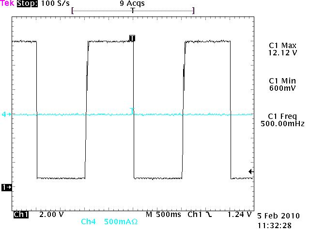
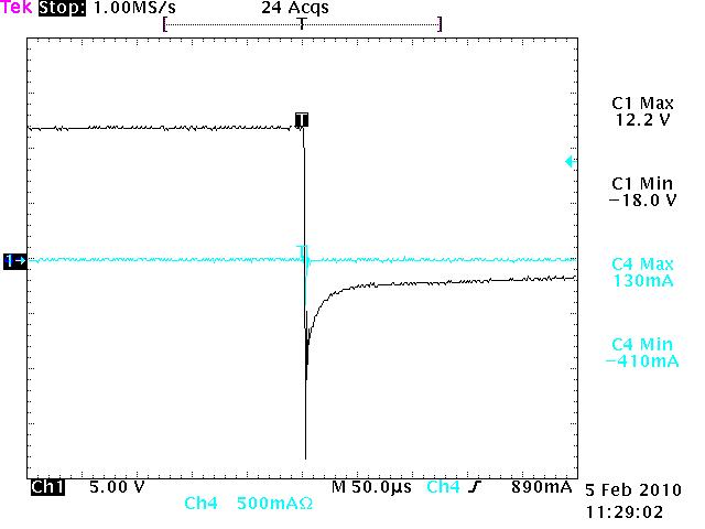
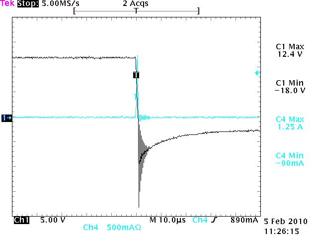
scope shots
Hi,
I'm doing all my best to study 'the switching' as JB emphasized,
1) Switching in the Differential Mode
2) (Inverted) Potential swithing
3) Crurrent Charge Pumping(Negistor) on the Semiconductor
Attached scope shots are captured from emitter to collector on the MJL21194.
I am afraid I'm right or not, so need any comments on these scope shots.
Regards,
JANGAttached FilesComment
-

This forum is preserved as a permanent archive. The community continues at eMedia Press.
- If this is your first visit, be sure to check out the FAQ by clicking the link above. You may have to register before you can post: click the register link above to proceed. To start viewing messages, select the forum that you want to visit from the selection below.

 Tweet
Tweet
Comment