 Tweet
Tweet
WELL I was testing the circuit to see if there was high voltage going to the output by unhooking the charge batt now i have now re done the circuit on a bread board and it works fine i think there must have been a problem in the original one i wired up XD
-
-
this might be stupid but I was thinking of a way to get the motor to self run and came up with the attached schematic ...
anybody tried something like this? Havent tested it yet but might give it a go.Last edited by Sephiroth; 12-16-2007, 06:21 PM."Theory guides. Experiment decides."
�I do not think there is any thrill that can go through the human heart like that felt by the inventor as he sees some creation of the brain unfolding to success... Such emotions make a man forget food, sleep, friends, love, everything.�
Nikola TeslaComment
-
damn... i just spotted a major flaw! back to the drawing board!"Theory guides. Experiment decides."
�I do not think there is any thrill that can go through the human heart like that felt by the inventor as he sees some creation of the brain unfolding to success... Such emotions make a man forget food, sleep, friends, love, everything.�
Nikola TeslaComment
-
Last edited by Sephiroth; 12-16-2007, 09:25 PM."Theory guides. Experiment decides."
�I do not think there is any thrill that can go through the human heart like that felt by the inventor as he sees some creation of the brain unfolding to success... Such emotions make a man forget food, sleep, friends, love, everything.�
Nikola TeslaComment
-
[QUOTE=Sephiroth;13947]second try
Hi,
I have been reading that John B. suggests that it is not a good idea to switch the charging battery and the primary battery directly, but to either use a capacitor or an inverter because of how the radiant energy works in the circuit. ( I must say this puzzels me as I have seen people swapping the batteries in the circuit all the time )
I also was thinking of making this circuit run continually and automatically. I am beggining to think the best way is to use capacitors to invert the radiant energy back to the batteries. I believe there would be less loss using this method as opposed to having an inverter. This would be doing it the "accepted way"
My idea is to have the circuit running on a timer at X number of hours it would switch batteries. I wish to build like 4 of these to run continually, the gain for me would be either excess charged batteries, or to put the wheel on a wind mill generator to have a continually supply of energy. I know the ssg does not supply much torque, but I was thinking if I had say 4 of these, I should be able to spin the windmill generator continually ( this is my theory )See my experiments here...
http://www.youtube.com/marthale7
You do not have to prove something for it to be true. However, you do have to prove something for others to believe it true.Comment
-
you might as welll give it a try because even if you fail you will learn and if you succeed you will learn so no matter the out come its a positive situationOriginally posted by Sephiroth View Post
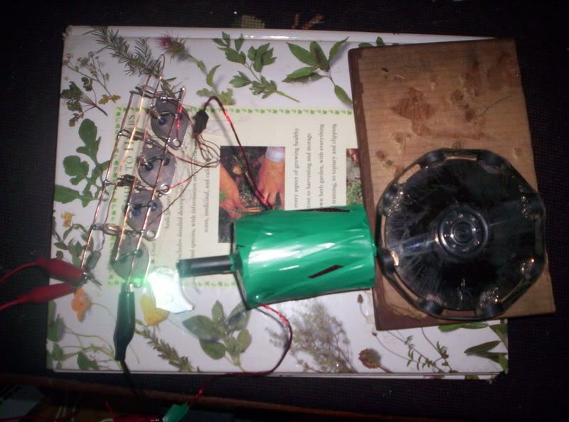
anyways heres my latest i got no multimeter( hopefully will arrive tomorrow) so i cant test it yet its 4 power one trigger 200' coil
Comment
-
trifillar and litz
OK iv been trying to figure this out, what is trifillar? Obviously sounds like three wires, a trigger, a power and what else? and are litz and trifillar the same? also does twisting the trigger and power wire together before winding make any difference?
Comment
-
the third could be a second power or a recovery depends on the energy recovery design and twisting the wires help reduce capacitance in the coilComment
-
trifilar
Trifilar is 3 wires. They can be "litzed" or twisted or not.
All 3 wrapped at same time.
I have a few "trifilars" that are equal lengths but the power/trigger are wound one way and the 3rd recovery winding is wrapped in the opposite direction.Sincerely,
Aaron Murakami
Books & Videos https://emediapress.com
Conference http://energyscienceconference.com
RPX & MWO http://vril.ioComment
-
why is the recovery wrapped in the opposite direction?"Theory guides. Experiment decides."
�I do not think there is any thrill that can go through the human heart like that felt by the inventor as he sees some creation of the brain unfolding to success... Such emotions make a man forget food, sleep, friends, love, everything.�
Nikola TeslaComment
-
reverse winding
7 years ago, I thought that is how it was supposed to be. To this day, I don't think there have been side by side tests.
Anyway, I'd recommend not doing it reversed but just wrap all 3 together.
On an old "dual battery charger" schematic, there is a dot in the coils indicating North and the recovery had the dot at the bottom...I thought that meant to reverse the winding but it means out of phase 180 degrees.Sincerely,
Aaron Murakami
Books & Videos https://emediapress.com
Conference http://energyscienceconference.com
RPX & MWO http://vril.ioComment
-
that's very interesting... did you read a post i made earlier about what i thought makes the transistor turn off to allow multiple pulses per magnet? I could be wrong (not being an electronics boffin) but as i understand if you have a standard bifilar coil with both wires wrapped the same direction and then pulsed a current through one of the coils a current would be induced in the opposite direction in the other wire. Is that right or have I misunderstood?
it could be that instead of the recovery coil being wrapped in the opposite direction, the diagram implied that the current flowed in the opposite direction?"Theory guides. Experiment decides."
�I do not think there is any thrill that can go through the human heart like that felt by the inventor as he sees some creation of the brain unfolding to success... Such emotions make a man forget food, sleep, friends, love, everything.�
Nikola TeslaComment
-
reverse winding
The dot at the bottom of the recovery winding indicates that it is for taking the spike when the field collapses in reverse polarity and the North is at the bottom.
Even if you have a 1 wire coil and apply power...during the applied power, you get counter efm coming in the opposite direction because of Lenz's law. After the coil is turned off, the loop is open and all the work that went into the pulse comes back converted back to voltage potential. The collapse spike is not the counter efm but happens afterwards.Sincerely,
Aaron Murakami
Books & Videos https://emediapress.com
Conference http://energyscienceconference.com
RPX & MWO http://vril.ioComment
-
thanks for responding!
so does that mean I've got the right idea?
if not how does the transistor turn on and off multiple times per passing magnet?I can't find any where that says what this diode (1n4001) is for but am i right in guessing that when the power coil fires, its magnetic field induces a current in the trigger coil in the opposite direction to the current induced by the magnets and thus quickly turns off the transistor as soon as it opens which results in the sharp pulsing? ...
...and allows for multiple pulses per magnet.Last edited by Sephiroth; 12-17-2007, 09:31 PM."Theory guides. Experiment decides."
�I do not think there is any thrill that can go through the human heart like that felt by the inventor as he sees some creation of the brain unfolding to success... Such emotions make a man forget food, sleep, friends, love, everything.�
Nikola TeslaComment
-
c rate= ah/20
is this watts ??Comment
Comment