 Tweet
Tweet
Originally posted by Jbignes5
View Post
-
Nice job on the multigap 7imix . This is going to be interesting Jbignes5. -
Hi Jiffy,
I have found that almost all of these technologies are related in one way or another. And a combination of these systems is probably whats going to get us over the top. The more Ive read into the ideas presented at this place the more I realize that it is all interconnected somehow. This particular thread seems to be right up your alley with the TC stuff however. Good luck guys.Originally posted by Jiffycoil View PostComment
-
Thanks Jbignes5
Wow. For now all I can say is fantastic stuff. I'm sure there are many of us who would like a pdf copy of this to have for future reference, so i made one up.
Thank you sooo much Jbignes5!
For a PDF copy download here, Donald Smith Practical Guide.pdf
I'm reading, reading, reading....Comment
-
From what I've seen, I could find no evidence of Don ever using a split primary. Believe me, I searched and searched. It certainly is possible that in every case he did and it was hidden, but if so me NEVER took a single picture showing the wires coming and going from the same side.Originally posted by Jbignes5 View Post
His references to the Tesla drawings clearly indicate IMO that he had a secondary wound in opposite directions. I've not seen a single reproduction attempt with this configuration. Or is it possible that the capacitor across one half of the secondary changes the phase relationship between it and the other half, without needing to wind it in the opposite direction?Comment
-
Reading this interesting documents, i concluded one thing.
He probably was creating a resonant tank at 40khz and than using a switching circuit witch take the magnetic fields and break them into megahertz frequency thus increasing the energy available.
E=F*H
So he had the energy stored in the inductor, and switched at higher frequency the circuit where this field is inducing. Or the receptor.Comment
-
shielding
The only thing that has to be shielded is the spark gap, and, if you use the enclosed gap and a low enough voltage, you won't get an xray nor will harmful waves get you. I've messed with this now for a while and have figured it all out finally. The entire device can be covered in a grounded case (faraday cage), minus an antenna which only needs to connect to the wires outputting the secondary coil where the diodes connect. The other end of the coil goes to ground, and, to my surprise, it doesn't even need to be grounded if the primary coil is one turn and the secondary 100 because the rectified ends of the coil can connect to two separate, isolated antennas mounted to your car (isolated from the chassis of course, and protected from flashover from a good dielectric and rain shields. The other end of the coil can go to the ground of the battery and a ground strap from the chassis can touch the ground to create the same, if not even more energy since the difference in potential acts like it's a greater distance apart from the elevation that the amperage nearly quadruples in the circuit. We only have to favor one end of the coil after it starts operating with a load since the tuning can be adjusted after a load is added to the output. Once the device is loaded, the battery could be disconnected and it will run itself. The key secret is the device that is at the end of the system. I figured it out and he insisted that the device didn't need to be used. That device adjusts the frequency for him, it uses an inductor coil, and, on the inside of the tube is a capacitor. It's the frequency adjustment filter that is obtained by matching the frequencies on the chart given in his pdf, however, the chart is wrong. There are online calculators to figure this out online, and, they are accurate as well.
Good luck, it is worth it's weight in gold because it replaces hydroelectric, solar, wind power , oil, gas, coal, and of course the ridiculously expensive paid for electricity. Don sold the technology to generating companies that are owned by energy companies, oil companies, etc., in the effort to eliminate fossil fuels and offer a free enrgy device without giving all of the secrets away, however, it took me years to gather the info and parts as some of the parts are difficult top even find, however, leyden jars will work just fine if built large enough. Government has done their all to threaten folks over it, however, they can't do much to those using these overseas!
My device was grounded in a stream nearly 200' lower than my lab, and, I built a curled copper antenna connected to an isolated high dielectric mica coated insulator I made from microwave shielding. The antenna was 30' over my roof and ground was 200 plus feet driven deep into my stream below me. The difference in potential would have been 1200 volts, however, I utilized the end of the coil which he stated was to build amperage, so, I have a massive difference in amperage, from 1/4 the added voltage to 1/8 more amperage. The current is so much that I use what I need, I can't possibly bog down the source, it's an absolute home run!
I use an older nst from ebay, and, an EPSCO 5500 volt enclosed gas discharge tube for the arc along with 5000 watt microwave oven diodes, connected in parallel. The output will create fireballs in a shorted condition, and, since it is made from cold electricity, the highh voltage is dangerous, but not nearly as devatstating as the stuff the utility company uses. I forced the system to run an output of 35,000 watts driving many of my neighbor's appliances, lights, irons, blow dryers, etc., all higher amperage devices and the device modified it's current to suit their operation, almost as if it were listening to what it needed. The circuit is amazing.. It certainly has a bunch of Tesla built in!!
DO NOT FOLLOW THE ONLINE DIAGRAMS!! ALL OF THE DEVICE's IMAGES ARE ONLINE TO MAKE IT FUNCTIONAL.. All we need to do is to connect all self healing caps of the correct value together to invite the flow of amperage for the coil that it's connected to .. the top coil is the amperage coil!
Good Luck To All! I have many answers. Please ask away..
I just pray daily to thank Don for being able to share before he passed on..


Originally posted by gmeast View PostComment
-
WOW thanks for the open door BelangersOriginally posted by Belangers View Post
My name is Michael Rowland I am 58 yrs old and wish to understand
the Don Smith device better. Which diagram do you recommend?
If I understand correctly the Don Smith device raises the voltage
and frequency with a series of coils to get the freedom from the
resistance by HIGH VOLTAGE.
Then after the spark gap Don showed in one video how he filters
the High Voltage and High Freq back down to 60hz. I see what might
be bucking coil arrangements but I don't know much.
This reminds me of the people who used a neon sign transformer
then shot that to a TESLA coil but Don reverses the process for
stand 60hz operation and comes out with more than he started
with.
Of course the grounds and antennas are not to be dismissed as
they play a big part of providing a pathway for energy to flow
into the HV field that is being generated.
I am all ears SIR. I saw all of your other previous posts and wondered
show I but in thinking maybe this might not be the best time.
I'm out here in Central Kansas with the wheat farmers.
I use the handle "BROMIKEY" because it is easy for folks to distinguish
between mike and mike's and more michaels
Comment
-
Hi Belangers:
First, let me say, this is the most eye-opening post I've ever read on this forum regarding the work of Don Smith. You've obviously spent an incredible amount of effort into understanding Don's work.
If you don't mind indulging a few questions, I've attached a diagram for reference.
Your seem to describe two systems, one system has two antennas and a ground, which under certain circumstances is not required and second, described more detail uses a roof antenna and ground in your nearby stream.
My questions:
1. Does my diagram accurately show the two antenna and optional ground set-up in concept form?
2. Does my diagram accurately show the inductor coil (primary?) and capacitor inside the tube? I assuming you are referring to the picture of Don's device with movable primary wrapped on a 1 to 1.5 inch PVC pipe.
3. How difficult is this thing tune? Building it trivial and no problem to do the tank circuit (RLC) frequency calculations, but we soon leave the domain if RF engineering with the secondary coil for the world of radiant / cold / static energy (call it what you will).
4. What about putting a tuning capacitor across the secondary to tune it to resonant? Don does this on his models.
5. Any benefits of using a center-tap to ground on the secondary or doesn't really matter?
Any insight would be appreciated, as your've the first person I've seen on this forum who really understands Don's work.
All the best, RogerComment
-
I am still learning from Don Smith theories and I have replicated a few of his simple circuits like the one that he shown using a car's ignition coil and one plate of the capacitor. He proves that in the other plate you can receive energy.
That is true as other simple circuits.
The main problem I think it is a bad understanding about how Smith's systems work.
Also, there are different circuits and not just only one as most people want to believe. All is said in his videos and documents. It would be better is he would explained a little bit more, but there is enought information to start performing some tests and trying to approach to the most-known circuit.Comment
-
For example Don Smith is using like a more advanced form of Avramenko Plug to charge the big bank of capacitors.
And also he is using a logarithmic scale to perform measurements instead the classic linear measurements. The scales that he uses are different.
I think he charges quickly a bank of capacitors using a resonant system. I have performed some tests and I can charge a bank of capacitors using 3 wires instead of 2 wires. You see how they charge faster and the charge is more powerful.Comment
-
Donald Smith device is based on a resonating system, but that system must turn the space surrounding it into a source of power by attracting ambient electrons with the resonance frequency speed, more frequency mean more power, Lenz's law is critical in his system and have to be avoided if we want to achieve OU device...
tuning process isn't difficult if we could achieve the resonance since we are working with electrostatic induction, standing waves will be a part from his system automatically ...Comment
-
Hello med.3012
I am drawing some schematics to better understand what I mean. I think Smith's system is a step-up transformer + advanced AV plug. It will take some 30 minutes to finish the drawing.Comment
-
Hello AetherScientist,Originally posted by AetherScientist View Post
yes i agree it's a step up transformer but the overall power depend on the voltage in the primary because it's responsible for ambient electrons attraction, more voltage mean more power, the length of wire in both side have to have a proportion, the primary is the quarter length of the secondary, so we don't have to worry about the used frequency in the primary reactor coil if the correct induction is used ( electrostatic induction = a kind of electromagnetic induction where electrostatic force is a part from the induction waves, this mean there is a standing waves regardless the frequency used ! )Comment
-
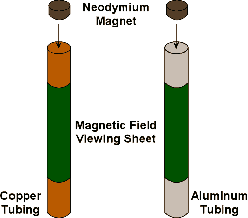
A brief visual explanation

Comment
-
It depends on a lot of different things, one thing is the thing you say.Originally posted by med.3012 View Post
Smith explains that when using resonance in AC there is not impedance (resistance), so there is superconductivity at ambient temperature. When there is not impedance, Ohm's law doesn't apply.
High frequency I think is more important than high voltage because while using HF the electricity travels around the wire, so there is not wire resistance, the second factor to avoid resistance is that impedance = 0 (no resistance). So in this case of superconductivity there is not a random bouncing of electrons (dissipation). Also, instead of linear scale (resistive case), it's applied a logarithmic scale (superconductivity).Comment
Comment