-
-
I mean driving the gate of the fet with the same wave form as the toroid puts out. Also reversing the "driving"polarity at the "gate".Originally posted by maxc View PostComment
-
Luc,Originally posted by gotoluc View Post
Looks like your circuit is exhibiting increased inductance but lacks Inductance/Capacitance.
Schpankme
"Inductance represents energy storage in space as a magnetic field." - Eric DollardComment
-
-
NIH..... great site... thise video on Lenz law is pretty thought provoking...
SQM Replication Project - Hyiq.org - UpdateComment
-
hi
hi there, i am working on the bedini and ron window motor,,,
can i use this battery to self recharge my 7amp 12v lead acid battery???
and can this circuit be a self runner and recharge my battery when ever it goes down???
can it work???
here is the circuit--
Free Upload Images
thxComment
-
Very Nice Work
Hi gotoluc,Originally posted by gotoluc View Post
This is very nice work, and, it is a fantastic way to find real resonance with the irf640 in your video... It seems to be most accurate resonance finder I have seen in my work to hunt or sweep for resonance. Your method showing the "blip" of resonance is very high ,so, there's no choosing whether or not you are in resonance, you just are because the calculating capacitor to the inductance gets you close, so, when you sweep a touch, you are there without question. There's no worries about catching the next harmonic because the capacitor calculation gets you next to the infinite impedance or "high point", and it is very evident once you get there.
I'm sure it has taken a while to figure out what was actually happening with the magnet, and I truly I applaud your efforts. This opens up a new method to draw from ambient which i'm confident can be made on a much larger level if we put our minds to it. I will be working on this, but, I must ask you, when you cut your toroid, did you put non conductives between the two halves? When you did this, did you use ferrite, or, did you use metglas? I have some small metglass halves that require a clamp to work and I am thinking that I could use them with a piece of plastic wafer or mica sliver to insulate between the two halves to eliminate unwanted connection of the forced back flux that would cause loading at the source normally.
If I go back to my experimentation to a video I posted called "finding resonance" for my HHO cells, I have a similar thing happening, however, my magnet is inside of the toroid and I do not remember how I wound it, but, I was able to bring the system down to zero amps and the HHO system was operating without any input according to my meters, but, I did find I was getting a rotational magnetic field that interfered with my meters and camera, so, I am hoping you didn't get a similar thing happening. I know your findings are quite different since yours is self running, but one question I have is this.. Did you ever get any substantial load to output from the self running system that doesn't stop its self operation?
does your circuit enhance powered circuits? since it self oscillates, perhaps with an input, the energy out will be multiplied or amplified at no cost to its input?
Thanks for sharing!
Marc

Comment
-
Hi Marc,
6 years has past since I first started this topic.
I don't know if I can remember details but for sure the toroid core was never cut. Maybe the space I'm referring is the windings if I did a back and forth winging instead of going around the toroid?... it's been too long and I don't have these anymore.
Also, I was never able to conclude 100% if there was excess energy.
Theses days I'm only working on non conventional geometries of motors and generator coil.
As for solid state devices that involve coils, switching and no movement, what I now believe is, if you want the environment to participate in such a device you may need to involve electrostatic and convert that to current, then you may get something extra.
I wish you luck if you venture this route.
LucComment
-
Looks like another self running coil by an investigator of the
experimental data. Ding. Hear that bell?
[VIDEO]https://www.youtube.com/watch?v=COH6PLjmJ3o[/VIDEO]Comment
-
Double Inductance.
@Gotoluc,
The inductance doubles with your bucking coils on the toroid core, but the bifilar series winding also gets the same results (Doubling Inductance) 4L?
"When you have a bifilar pair like this, you can measure the inductance of one of the coils, ignoring the other; call that value of inductance L.
Now, if the two coils are connected in series aiding configuration, the inductance will be 4*L.
If they are connected the other way, series opposing, the inductance of the combination will be very small".
JLN forgoes the bifilar wrap iin his magnet toroid coil generator; 2SGen.Last edited by Allen Burgess; 01-19-2017, 06:39 PM.Comment
-
Synchro coil.
@Gotoluc,
I attached magnets to the ferrite core of a tesla bifilar solenoid power coil, with an electrolytic capacitor and fast diode in series with the coil. I achieved OU results years ago this way.
Thanks to Gotoluc; We've determined that the series bifilar coil will "double" the inductance, and that a correctly spaced core magnet can halve it.
This same formula will yield an OU pulse motor that delivers output from the resonating magnet core power coil at the correct frequency and duty cycle. At that ratio, the coil has the capacity to store a magnetic force equal to the strength of the permanent magnet. I demonstrated how the displaced permanent magnet field generates power when it restores itself to equilibrium in my Dragone video.
15 khz equals 250 rpm; Pulse width tailored to % by circuit! At the correct speed and pulse width the magnet core bifilar power coil will begin to generate OU output, just like Luc's toroid.Last edited by Allen Burgess; 01-20-2017, 10:23 AM.Comment
-
Multiplication of bifilar inductance.
"Inductance is (L1 + L2)*M where L is inductance of each coil (say N turns per coil), and M is a mutual inductance factor (ranging between 1 and 2). If the winding was made from one wire with 2N turns, then inductance would be 4L (with same geometry). Its same as having two inductors of L and bringing them close together, their fields interact and you get a mutual and a stray coupling component".
It would be difficult to direct a power pulse through Luc's bucking coils, but the Tesla bifilar appears to generate the same doubling of inductance through the interacting fields in the coil. The bifilar makes a great pulse motor power coil.Last edited by Allen Burgess; 01-20-2017, 12:21 PM.Comment
-
Inductance controller.
Imagine wrapping an electro-magnet with a bifilar coil. This would allow us to regulate core saturation and coil inductance with a D.C. potentiometer, rather then toy with a permanent magnet gap. Spinning a magnet rotor in close adjacency to a ferrite core will saturate the core beyond a level required to balance the inductance to the magnet force stored in the coil to generate power. We need to reduce internal core saturation to balance the increase in saturation level from the accelerating rotor magnets, to easily regulate a constant output power.Last edited by Allen Burgess; 01-21-2017, 12:24 AM.Comment
-
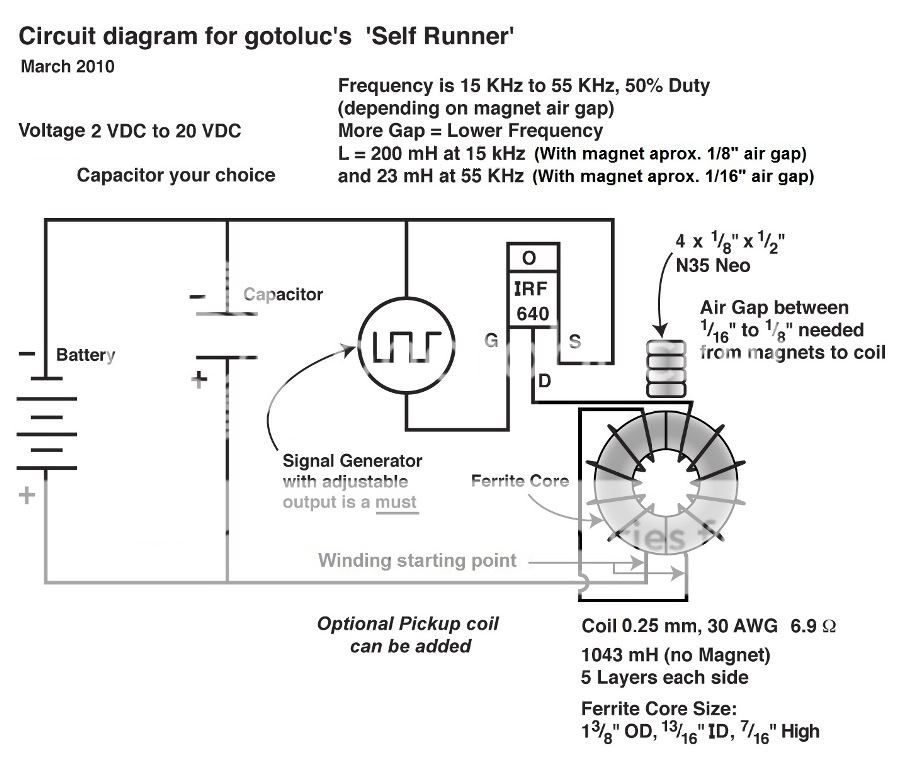
Electro-Magnetic Winding.
Luc uses 4 -1/8" X 1/2" neo magnets, spaced 1/8" to 1/16" from the "Self Runner" coil. We can match that magnet force with a third winding next to the ferrite with sufficient turns and D.C. current; That way we can precisely control the saturation level and coil inductance with a potentiometer. It may be possible to spin a miniature magnet rotor inside the toroid air core, while it's powering itself.
A Tesla bifilar, with a third electro-magnetic winding tightly wound directly on the toroid core, should work the same way: As a self powering MEG and a pulse motor power coil. Once the saturation circuit's in place, the permanent magnets can be repositioned to conserve power with the additional benifit of a fine inductance tuner.
The bifilar coil fields interact just like Luc's counter wound adjacent coils, to boost inductance two times through "Mutual Field Coupling".Last edited by Allen Burgess; 01-21-2017, 01:59 PM.Comment
-
3rd wrap.
JLN winds up with his magnets inside the toroid air core. Let's say we positioned an axial polarized cylinder inside the air core of a toroid with an electro-magnetic wrap. A N.S. pole will appear in the D.C. toroid magnet coil that a free orienting magnet would choose to align with. After energizing the electro-magnet coil, both the field from the permanent magnet cylinder and the electro-magnet coil would combine to raise the core's saturation level. This saturation level should equal half the inductance drop for a Tesla bifilar or bucking pair coil like Luc's. The coils can generate "Dragone" power when the coil inductance and magnet field strength are balanced. This means the coil has the storage capacity to generate a magnetic field equal to the ones induced by the permanent magnet and electro-magnet coil combined.
Now we have a permanent magnet and a electro-magnet coil teamed up. The potentiometer to the D.C. coil acts as a fine inductance tuner. When the magnet cylinder in the toroid core moves, the coil inductance changes. Turning the cylinder magnet 90 degrees coupled with a current surge in the electro-magnet coil should equalize inductance at a constant non fluctuating level. At maximum efficiency R.P.M., the rotating magnet should supply all the saturation the core requires for power generation balance.Last edited by Allen Burgess; 01-22-2017, 04:00 PM.Comment
 Tweet
Tweet
Comment