Announcement

Collapse
No announcement yet.

Donald Smith Devices too good to be true

Collapse
X
 
  • Filter
  • Time
  • Show
Clear All
new posts

  • Originally posted by Guruji View Post
    I meant what can I get from this setup? Can I light up a heater?
    with this don smith circuit u get 6000 watts of power. i posted earlier the similarity of don smith circuit with ac adaptor just to show it works like ac adaptor circuit except the core is air core and primary and secondary are reversed.

    but the middle join of don secondary must be earthed its important.

    try to contact MR. Dragon/Mr. woopy if u r interested in 3 plate capacitor induction charging and lighting the bulb if u find Don smith circuit quite complicated. mr. Dragon method also leads to the same goal of free energy.


    rgds

    ....
    Last edited by zilano; 05-27-2012, 08:41 PM.

    Comment


    • Originally posted by zilano View Post
      wellthe meter u posted as pdf is good. it covers the range u need.

      (well find an lcr meter which can measure from pf range to uf range and from uH to mH also there is a cheap way to make ur own LCR meter as under)


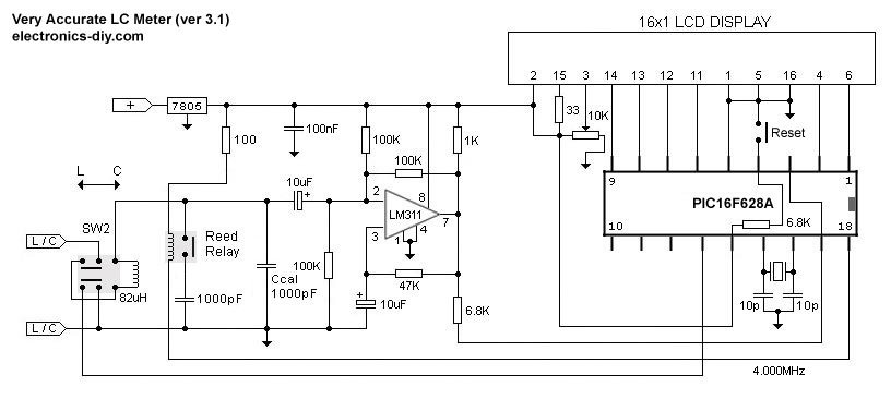
      Very Accurate LC Meter based on PIC16F628A

      Accurate LC Meter Part's List:

      1x 16x2 LCD Display with Green / Blue Backlight
      1x PIC16F628A Programmed Microcontroller
      1x LM311 IC
      1x Accurate LC Meter PCB with red solder mask
      1x Enclosure
      1x Gold Plated Machined 18 DIP IC Socket
      1x Gold Plated Machined 8 DIP IC Socket
      1x L/C Pushbutton Switch with Black Cap
      1x Tactile momentary reset switch with Black Cap
      1x Gold Plated 16-PIN LCD Female Header
      1x Gold Plated 16-PIN LCD Male Header
      1x Gold Plated 2-PIN Header
      2x Gold Plated 1-PIN Header
      1x 4.000 MHz Crystal
      1x High Precision 82uH Inductor
      1x 5V Ceramic Reed Relay
      1x LM7805 Regulator
      1x 10K LCD Contrast Trimmer
      2x 1000pF High Precision WIMA Capacitor
      1x 100nF High Quality WIMA Capacitor
      2x 10pF High Stability Capacitor
      2x 10uF Panasonic Capacitor
      1x 10 1% Metal Film Resistor
      1x 1K 1% Metal Film Resistor
      2x 6.8K 1% Metal Film Resistor
      1x 47K 1% Metal Film Resistor
      3x 100K 1% Metal Film Resistor

      Accurate LC Meter's Technical Specifications:

      Voltage Supply: 6 - 16V
      Accuracy: 1%
      Full Automatic Ranging
      Inductance Resolution: 10nH
      Capacitance Resolution: 0.1pF

      LC Meter's Inductance Measurement Ranges:
      - 10nH - 1000nH
      - 1uH - 1000uH
      - 1mH - 100mH

      LC Meter's Capacitance Measurement Ranges:
      - 0.1pF - 1000pF
      - 1nF - 900nF


      About Accurate LC Meter
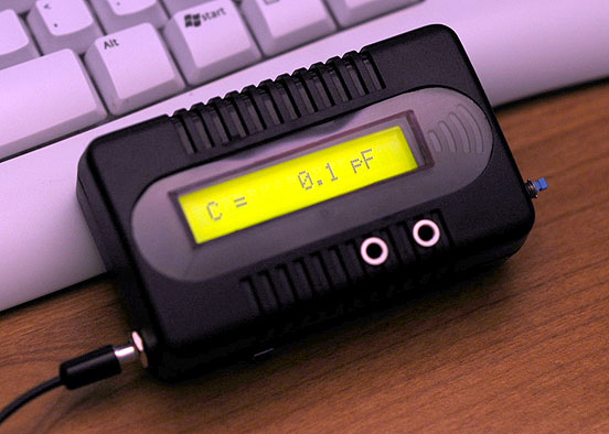
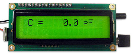
      This is one of the most accurate and simplest LC inductance / capacitance Meters that one can find, yet one that you can easily build yourself. This LC Meter allows to measure incredibly small inductances starting from 10nH to 1000nH, 1uH to 1000uH, 1mH to 100mH and capacitance from 0.1pF up to 900nF. LC Meter's circuit uses an auto ranging system so that way you do not need to spend time selecting ranges manually. Another neat function is reset switch that will reset the initial inductance / capacitance, making sure that the final readings of the LC Meter are as accurate as possible.


      Special Edition Accurate LC Meter Kit


      ''

      Thank you for your quick replay...
      About self made rlc meter you posted, I knew ;I thought about to make one for myself but the problem was the PIC16F628A need to be programed...I have no knowledge in this area...so must buy one.....

      Regards
      Mike

      Comment


      • Originally posted by atta View Post
        Hi nutgone!
        Have u resolved shocks problem?
        I faced the same problem of shocks but i suspected either winding arching or the transistor!
        I did replace both for my satisfaction and it resolved the problem.
        Perhaps it may also resolve it for u as well!
        good luck.
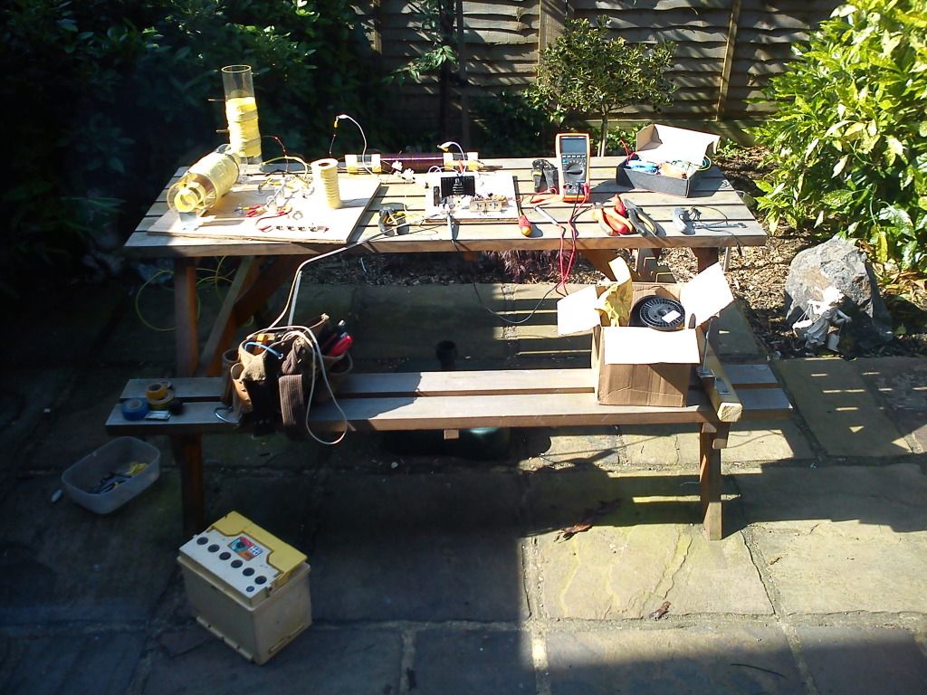
        I had another play around today. I took off the 8 turn coil from the HV module & added some more winding tape, then I re-wound it, more centrally this time, & taped over it (I haven't got any tube the right size to make it sliding, & I'm not sure it really needs to be here).

        I also removed the ferrite rods from the centre, & it seems to be running a lot better.
        I thought the FET was cooked, but it seems to be working. I was trying to take frequency measurements but couldn't get anything unless the FET had some work to do (ie: unless it was running a coil or connected across a resistor).

        Now my next question; my frequency readings are not stable, I guess this is due to the spark gap. Will this steady out as I start to add caps & tune in some resonance???
        I'm still waiting for my LCR meter to turn up from China (just a cheap one, but it should do the job) hopefully then I can start measuring some inductances & parasitic capacitances & start tuning these coils for resonance.

        I have no idea if my variable resistors are still live, I daren't touch the damn things! They are still doing strange things when I have the screw driver on them for adjustment, but they settle down when I remove it.

        Here's a quick pic of how I had things today, any suggestions gratefully received.
        Also, I am using a battery, not mains, & I do understand this is little more than a very dangerous toy (which interferes with the TV reception) until I add some caps........

        Comment


        • vidbid is missed!

          @ david fine

          do u know where is mr. vidbid i hope he is well.
          have not seen around for a while. he had a lot of insights in kapanadze and sr193 replications and circuits.

          rgds

          ....

          Comment


          • Hi nutgone ,

            This might be a little further out on the " FRINGE " but I wondered if you had in advertantly stumbled into the phenomenon related to what Tesla found , as force fields . Not so much as movement of metal objects but the other quality , that localized metal objects became electrified .

            edgy enough , eh !

            I can't show my stuff yet as I have not been able to run tests as I'm finding the back end " dark energy " converter is a bit tricky and still in design at the moment . Any photos or drawings would be premature and I have not made any claims yet .

            Regards Jacqui .
            Last edited by Jacqui; 05-28-2012, 09:43 PM. Reason: spelling

            Comment


            • Originally posted by zilano View Post
              @ david fine
              do u know where is mr. vidbid i hope he is well.
              have not seen around for a while. he had a lot of insights in kapanadze and sr193 replications and circuits.
              rgds
              ....
              He got a job

              What insights do u need? u have 5 working units for friends and 10kW for yrself

              Dyna writing a book (attach) how to make a DS WORKING device you better start working too
              Attached Files

              Comment


              • Hi all

                going on my experiment

                hope this helps

                good luck at all

                Laurent

                charging by induction approach 2.wmv - YouTube

                Comment


                • Vidbid

                  Zilano,

                  We used to correspond quite a bit. When he quit responding to my e-mails I sent him three or four more e-mails but he never got back to me so I finally said bye to him and wished him good fortune. I don't know what happened with him. He was a very unique interesting chap. He taught me some interesting things off-forum.

                  Best Regards,
                  David Fine


                  Originally posted by zilano View Post
                  @ david fine

                  do u know where is mr. vidbid i hope he is well.
                  have not seen around for a while. he had a lot of insights in kapanadze and sr193 replications and circuits.

                  rgds

                  ....

                  Comment


                  • Originally posted by RAD-HHO View Post
                    Good to hear of your success.

                    So you have two mini bobbins, one for L1-L2, and one for L3-L4?
                    Both bobbins are wound the same? 9" #26 MW wound on top of 36" #30 MW?
                    I am assuming #26 MW means 26 AWG magnet wire?
                    Is the L4 coil open ended as in your schematic?
                    Air core, or welding rods?
                    Do you have any clear pics of your bobbins?
                    Any video of your setup running?

                    Thanks for sharing
                    L1 & L2 are enclosed in a blk box 3.3" x 2.1"x1.4" and the bobbins fit inside on circuit board. L3& L4 arein a box 4.2"x2.7"x 1.6" with the inverter electronics. and the transistors are mounted on large heatsinks outsid the box. That is correct that is the size magnet wire I used. Currently it is air core butt I plan to add powdered ferrite mixed with epoxy or something simular because the bobbins come with a hollow center for a insert or a paste for ferrite or what ever.There are several pictures off the device at different stages in previous post on the forum. if your really interested in seeing them I could post them again,but it would eat up my allowed memory bites of postings. I dont have a video camera at this time maybe in the future. I spend most of my money on parts and supplies for my experiments

                    Best Wishes
                    S-N-E

                    Comment


                    • Love your videos and work, woopy!

                      Found this video where he touches metal objects to ground and his bulb brightness increases. A pair of wire cutters makes brighter than a bigger copper pipe. At 2:55 he deliberately touches the sharp pointed end of the cutters and got the brightest light of all. As you say....hmmmmmm, not normal

                      1. Does that happen because the field strength increases at sharp points?

                      2. Does the metal object, after running connected for a period of time, hold a positive charge and replenish through the air or does it's input to the system slow down (not likely as that much mass has a million or more coulombs worth of free electrons) ?

                      3. Can the current flowing through the ground wire be measured?

                      Originally posted by woopy View Post
                      Hi all

                      going on my experiment

                      hope this helps

                      good luck at all

                      Laurent

                      charging by induction approach 2.wmv - YouTube

                      Comment


                      • Spray on Dielectric

                        Originally posted by nutgone View Post

                        I do intend to use acrylic, or some other board which is a better insulator (or just better insulated terminal blocks).
                        I found this, sprayon....ten second drying time.
                        2300 volts/mil (.001 in) clear dielectric strength.
                        2600 volts/mil in red
                        1900 volts/mil in green epoxy (longer drying time)

                        Found here for anyone interested.
                        Attached Files

                        Comment


                        • Originally posted by OrionLightShip View Post
                          I found this, sprayon....ten second drying time.
                          2300 volts/mil (.001 in) clear dielectric strength.
                          2600 volts/mil in red
                          1900 volts/mil in green epoxy (longer drying time)

                          Found here for anyone interested.
                          Thanks
                          Half of the Answer is knowing the right Question

                          Comment


                          • Originally posted by woopy View Post
                            Hi all

                            going on my experiment

                            hope this helps

                            good luck at all

                            Laurent

                            charging by induction approach 2.wmv - YouTube
                            Interesting theory Woopy.. your looking at it in a logical way, that is - your following the visible connections that would lead the energy back to the batteries and your probably right in part. But... if you look at the capacitive aspect of it, your L1/L2 coils are working as a capacitive link which leads the energy directly to the battery(s).

                            Your also setting up standing waves in the earth which is another topic altogether so for the moment consider what we are doing to the local ground environment. When the coil goes positive it repels all the pos charges away from the ground connection and attracts the neg - they rush in, in an attempt to counter the imbalance creating a ground current which consequently your trying to trap these charges in your collector cap. When the line goes neg the same thing happens only it's in the opposite direction or an outgoing current flow.

                            It's getting late... great videos, keep up the excellent work !

                            Comment


                            • Originally posted by ewizard View Post
                              I just grabbed a 473 page document that hartiberlin (OU admin) found on the TPU and also some excellent Don Smith material in this I haven't seen before. The author of the document has really put a lot of work into analyzing a lot of information in great detail. I think anyone interested in replicating Don Smith's work work will benefit by looking at this and in particular pages 449 to around 453 as he states this IS the secret to successful Don Smith replication. He backs up his work with a lot of math, diagrams, tables and graphics. I've downloaded it from scribd.com but as scribd requires an account and some uploading to get files I have re-uploaded it to rapidshare so everyone can grab it easily. Click Here to download from rapidshare.com (PDF file)

                              Hey Ewizard

                              I don't know for sure what the problem is but I have been tring to download your link all day. And I keep getting an error message. Then it goes to another screen in german that one of the line says"der link ist falsh" and I interprett that without an interpreter "the link is false of this is a false link" Just wanted to let you know

                              cheers
                              SLOW-N-EASY

                              Comment


                              • Battery Capacitor Sandwich

                                Originally posted by woopy View Post
                                Hi all

                                going on my experiment

                                hope this helps

                                good luck at all

                                Laurent

                                charging by induction approach 2.wmv - YouTube
                                @Laurent

                                Awesome video! I'm working on my radiant collector / radiant exciter circuit, too. I hope to have it completed soon, just as soon as I receive all of the parts.

                                Instead of using a copper plate, I'm going to try placing the capacitor directly between the batteries.

                                That should be interesting.

                                Best regards,

                                Berg

                                Comment

                                Working...
                                X