1939 gravity power machine translation coupler connection
Goldpro,
Look at my video from 0:16 to 0:45 or so. https://www.youtube.com/watch?v=JolNozy8UEY
Without me touching it, the lower shaft is locked in a vertical position with the translation coupler and the input lever (short demo rod on top) is locked in position to the plate as well. However, when I rotate then, you can see that the plate does not slide down the lower shaft and the upper short rod does not slide down through the plate either.
Both are held in place in their vertical relationship to the plate. However, they are able to freely spin on their own axis without being locked to the plate.
-
collar bearings and rotating plate
With that bolt in the side of the plate, doesn't mean it is a set screw to hold the lever in place if the lever rotates on its own axis the the plate moves with it - as mentioned in the other forum, could be a grease fitting - or a set screw for a shaft collar that lets the lever freely rotate.Originally posted by goldpro View Post
Some of the bearings I use have the collar built into the bearing with a set screw, which just means the shaft won't slide up and down the bearing but will rotate with the bearing.
Here is the exact bearing I bought for that purpose:
Dynaroll S5FPB2ST Flangette Collar Bearing, .5" Bore, 1.437 Width, 2-11/32" Length: Flange Block Bearings: Amazon.com: Industrial & Scientific

That is a different bearing than mine - can't find a pic of mine with the set screw for the collar but the collar is INSIDE the bearing to lock on to the shaft, but it lets the shaft still spin.
Just search for: collar bearing
and you'll find all kinds.
If you just rotate the plate, that thing will continue to move around and if you give it lever action, it definitely won't go back and forth - it will rotate.
Eltimple showed in his earlier vid that he only had the back and forth action with no ellipse or rotation and it moved the mechanism in a circle just like I demonstrated with the paper demo with my graph paper cutout of the translation plate.
When you kick the lever in one direction, because of its connection point to the plate in relation to the weight, it forces the rotation to happen and the upper weight has enough mass and momentum from that kick to keep it going in a circle.Leave a comment:
-
Thanks for your comments Aaron.
I look forward to seeing a demo of the shaft collars.
to put my idea another way...because of the loose coupling (gimbal or similar) there's no guarantee that the translation plate will rotate when the input lever rod moves in an ellipse or back and forth.
As I understand it....even if it moves slowly...or fast, it could go back and forth all day and never make the upper weight go around.
In a sense, the lower weight is hindering the upper weight and translation plate from turning because of it's angle in relation to the plate
Or if one goes around the other 3 might not...then it's out of balance.
that bolt is clearly seen at about 30 seconds of the video.
TomLeave a comment:
-
extracting energy from the gravity machine
The angle of the lower weight bracket does does not stay consistent... although it is at the bottom of the lower shaft, it still goes in an ellipse and not a circle but even if it did, are you talking about extracting mechanical work or electrical work from that directly or using the ring like a pulley to directly turn something? Oval rings could obviously be made, but I'm not sure of your exact method of extracting energy from it yet.Originally posted by sly3000 View Post
It is possible that the output wheel serves as a flywheel that is a balanced circle to keep the momentum going. I've seen some references to the lower weight being like a flywheel but those that said that don't know that a flywheel should be balanced to act like a flywheel. There is some momentum in that lower weight, but it will not give many rotations after it is turned off because it is an imbalance rotating around an axis which has a fixed angle (if off) so it is bucking up against gravity on half the rotation. If it was a flywheel, when turned off, it would act like a flywheel but it doesn't. The principle is different - I know you didn't mention it, but I want to because it isn't the same thing.
So that lower wheel might be necessary.Leave a comment:
-
1939 Gravity Power
Tom,Originally posted by goldpro View Post
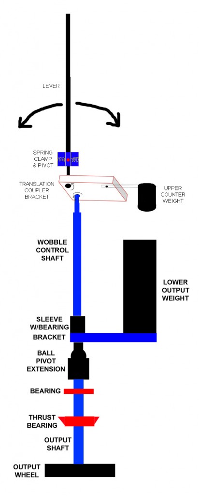
2 gimbal bearings or other method to allow the translation coupler to freely swing around the bottom of the lever and around the top of the lower shaft - and because of the movement of the plate in relation to the angle of the lever and shaft has to give some swivel action.
The input lever length is a fixed length both above and below the pivot location for the input lever. So although the input lever is in a bearing setup on the translation coupler, after it pokes through the bearing, there can be a shaft collar to fix the height of the coupler plate in relation to the input lever. And likewise, at the top of the lower shaft coming through the translation coupler through a bearing, a shaft collar (with set screw) can be there to keep it there as well. I used some bearings that had built in set screws that let this happen and it keeps the translation coupler, not at a perfect horizontal but at a fixed height nonetheless. The corner with the upper weight will be hanging at the lowest point. When rotating, if fast enough, the plate will get more horizontal but that is just because the lower weight has some outward force that keeps it from sagging.
4 weights on all 4 sections of his "4 pole" system will always have the opposing sides synchronized as dictated by the position of the levers, which dictate the position of the translation coupler, which dictate the position of the upper weight.
Would need to see the bolt pointed out in a pic.
We never get to see it start up from a stop - the video only shows it either stopped or with it already up to speed. Starting it up slowly lets the system stay synchronized. Starting to fast makes the upper translation coupler spin around but the lower weight won't catch up - I show that in some of my videos.Leave a comment:
-
easier way to output
Hi Aron
Follow me please :
Do you see the lower output weight ?
look at the Bracket which carry the weight (in Blue color)
i think if we can attach a metallic big ring on the Bracket Diameter (the bracket when it move a complete circle , it shape a circle which has a diameter right ?) so we can attach a ring on the weight itself or on the bracket , which it is going to rotate with it and we can transmit it is energy directly from it !!!
and this ring can be used instead of the output wheel !!!!

what do you think ??Last edited by sly3000; 06-18-2014, 10:20 PM.Leave a comment:
-
If I understand what folks are saying correctly then the latest
idea is that there are 2 gimbal bearings in the translation plate.
one for the lower tip of the input lever rod and the other for the top of the lower weight wobble shaft.
Have I got that correct?
If so ...what holds the translation plate horizontal when the machine is stopped?
There's a big weight on it, so wouldn't the plate tip over in a direction that would be perpendicular to a line drawn between the two gimbal bearings?
Wouldn't it tip over as far as the gimbals would allow?
Also, how do we coordinate the 4 upper weights and keep them in step with each other so as to cancel out their off balance motions if there are gimbals bearings at the end of each lever rod?
What is the bolt for that sticks out of the side of the translation plate in line with the input lever rod's tip?
I have a different idea of how the upper part of the machine works which I've built into my meccano models and it STARTS to move the upper weight and continues to move it better than I could get it to move using the ideas presented in this forum. However my smaller scale version might not work nearly as well as a full scale build so what I'm experiencing might be invalid.
I don't think there is much of a whipping action of the lever rod/translation plate when starting up and things are moving slowly.
I need to get some pictures taken or a video but I don't have a video camera.
TomLeave a comment:
-
Yes Fernando, i was the first one to break that story as i speak Spanish, i passed it on to the English speaking groups ..the Fernando also has a falling weight lol...
yes Shylo... i have added a load in a way by showing the thing stalled...but you will just have to wait while i get the drives sorted out...i also have to replace the current weights , which were there purely for setup...The build has moved on a lot now so the time has come to accurately record weight etc , and add some much heavier lead ones and for that i am waiting for scales that will also do the dyno testing. I live in the middle of the Atlantic so the post takes a whileLast edited by eltimple; 06-18-2014, 01:43 AM.Leave a comment:
-
Eltimple - gimbal video
Ok, makes sense.Originally posted by eltimple View Post
Your demo video with the gimbal should be getting a few more hits today. I put it in a newsletter.
By the way, it was your replication of the Fernando mechanism where I was able to see what it was for the first time.
Leave a comment:
-
adding the load
Hi Craigy, have you added a load to the bottom?
It's strange if you hit it too hard with a load the upper part will just spin. A gradual increase lets the bottom get going.
Adding weight puts extreme pressure on the lower bearing of the output, also when you draw power.
Mine blew apart today.
The upper part is just like you show.
Back to the drawing board.
artvLeave a comment:
-
no i have not done any rotating yet...i have a linear drive that will just bolt on, (linear is a very narrow elliipse...lol )
the spread sheet is also good to understand what forces you might expect to see asumming it works..So i am now beefing up the mechanism so that the energy isn't just lost in vibration
But i will try each one...its unfair not too.Leave a comment:
-
input mechanism?
Eltimple,Originally posted by Aaron View Post
Very important question I was hoping you would answer. How were you driving the top of the lever connected to your gimbal?
You responded about the scale of the system, but you didn't comment on how you're driving it. Seems you just connected a motor to a pulley or something and simply rotated the input lever in a perfect circle.Leave a comment:
-
scale matters
The basic Bedini SG using a roller skate wheel and single winding works. It behaves exactly like the scaled up models. However, the output is feeble and it cannot push the battery enough to see the gain. Take the same thing and put 7-8 power windings and a bigger rotor, you get more charge to the battery to see the gain and there is more mechanical work compared to the electrical input.Originally posted by eltimple View Post
Virtually every single system we have, electrical or mechanical, that works at over 1.0 COP has a greater gain the bigger it is. We know because measurable results tell us.
For example, if you have a small electrical system and we're dealing with 3 volts and we have a diode on it with a 0.6 volt drop, we have 2.4 volts on the cathode - that is a 20% loss.
But if we have a 30 volt system and put the same diode for a 0.6 volt drop, we have 29.4 volts on the cathode - that is only a 2% loss...huge difference.
With mechanical systems, it is no different...scale it up and all losses are a smaller %. With the exact same bearings I have with a smaller aluminum weight at the bottom, the mechanical loss is a certain percentage compared to the scale of the mass. If I put a weight 4 times heavier, which the bearings can handle no problem, the mechanical bearing friction is a much smaller percentage compared to the mass of the weight.
Some may use it as an excuse but we know it to be an empirical fact based on the results we can and have measured.
Just because the math remains the same proportionately for any scale, that doesn't have anything to do with how the machines operates on different scales and there is a difference because of some of the reasons I explained above.
Just food for thought.Leave a comment:
-
no if it works then scale has no bearing...infact the common excuse for overunity machines not working is always if it was just a little bigger it would work.....that is a great mis-conception. If a small weight is big enought to affect the system by falling and hence moving the shaft towards the new COE. then its big enough.
centrifugal math means that when you double the speed you quadruple the force, that happens at the macroscopic or the enormous
but the spread sheet will work with any size you wantLeave a comment:
-
dont think that the any change of scale would do different results
but you need to scale weight and size of all parts precise
I don't know did any of you notice that the top lever(rod) that is moving the
plate is pretty long and its mass is laying down on gimbal,therefore helping to
create a more force with less input powerLast edited by turbogt16v; 06-17-2014, 08:25 AM.Leave a comment:
Leave a comment: