Announcement

Collapse
No announcement yet.

William F. Skinner - 1939 Gravity Power

Collapse
X
 
  • Filter
  • Time
  • Show
Clear All
new posts

  • Aaron
    replied
    Skinner machine NOT a flywheel

    Originally posted by purelyprimitives View Post
    I think you are better off with one. At least then, you have some asymmetry and inertial propulsion as you say. The more I study Mr. Skinner's machine, it appears to be totally balanced and symmetrical which is not where you want to be.

    For instance, we know that opposite sets of weights are constantly 180 degrees out of phase. If you were to measure two sinusoidal waveforms on a scope that were 180 degrees out of phase and hit the 'add' button, they would cancel each other out. So I would say that there is nothing 'additive' here. In fact, it would seem to resolve into being just a fancy flywheel. And we both know that there's no OU in a flywheel.
    Multiple is better - scaling up to 4 pole means all frictional losses for the mechanism to rotate the common output wheel are divided by 4 instead of one quarter taking the whole loss, etc...

    Asymmetrical in each quadrant is desirable and that is what is happening, but we don't want the inertial propulsion, we want all the output force to be concentrated into the output shaft and not to be dissipated in the whole machine moving across a floor.

    There is no relationship with the Skinner machine and a flywheel - not in a "one-pole" system and not in a "four-pole" system.

    I'm seeing the flywheel conversation go around in various areas, but there is no flywheel action here. I explained that before and I see Mike touched on it a bit.

    Here is an extension to my past explanation and just looking at the operation is prima facie evidence that there is no flywheel action in the machine. That is not what it is about.

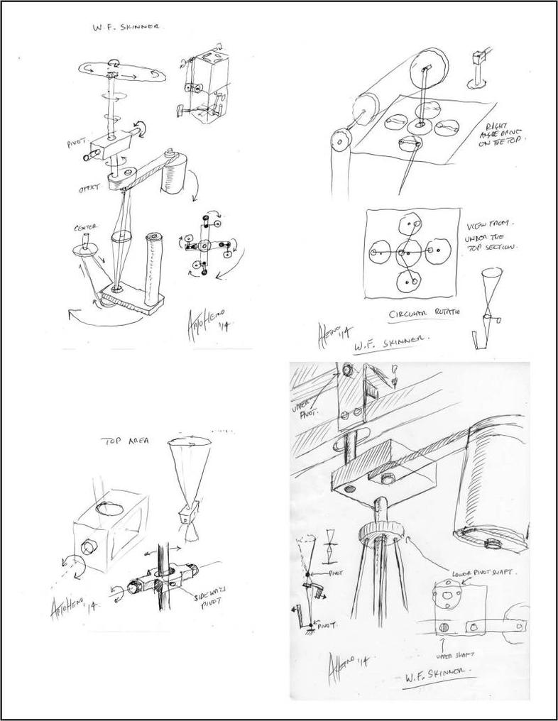
    If the output is suddenly locked up - the lower weight will only swing around for a short period of time. As the lower shaft is locked in position and in its angle, there is the inside of the incline and the outside of the incline.

    As the weight moves around towards the outside of the incline, it goes up against gravity losing some of its momentum and on its way back down, it picks up a bit, but the overall loss is greater than the gain meaning it is absolutely does not function as a flywheel.

    If we have the same weight as the lower weight evenly distributed in a circle around a shaft and it is going the same speed as the Skinner machine and the mechanism stops, but the weight is allowed to continue to spin, it will spin for quite a while because of the even distribution of weight - even if it was on a tilt.

    If you want to talk about flywheels, it has to be consistent with how a flywheel operates.

    If we have a merry go round that is perfectly round with even distributed weight and it is spun, it will last a while because of this - it is designed to keep the momentum going with the least amount of loss.

    Now take that same merry go round and put a protrusion on one part of it that hits a fixed protrusion from the ground every time it goes around one rotation. Each time it gives up some motion and slows down - that is a very sorry flywheel as it is completely contradictory to what a flywheel is. Well, this particular example is exactly what the Skinner lower weight is - NOT a flywheel. Even with the machine in motion, the lower weight is NOT a flywheel as it counters the need to have evenly distributed weight in order maintain its movement with the least amount of loss.

    I really don't see how it can be logically argued to be a flywheel when the necessary parameters that are needed to be met are not even incorporated into the Skinner machine - not even in the slightest bit.

    Leave a comment:


  • marxist
    replied
    drawings, weightlessness and acceleration

    Originally posted by Dave Q View Post
    ....
    The long elliptical travel shown in his drawing ...
    Hi Dave,
    thanks again for your work. I hope none that of the following observations will offend you.
    Just to avoid misunderstandings:
    There are no drawings available, done by Skinner.
    The drawings you refer to were done by a member of this forum and depict this member's ideas based on the Pathe video of 1939

    @ Dave and all
    Please note that a mass flying out in an orbit exerts no force in the vertical direction (it only exerts force in the horizontal direction aka "centrifugal").
    This is how weightlessness is simulated/produced.
    Such a mass is weightless.

    So while the upper mass (wrongly called "weight") is flying about in its orbit, no work is done while it is being lifted. And no work can be harvested by lowering that weight as long as it remains spinning.
    Originally posted by Dave Q View Post
    ...But only if the lifting and falling moments balanced out.
    If my above statements are true, then the lifting and lowering of the weights with Dave's linear drive mechanism will not produce a momentum and consequently lifting and falling moments can not balance out.

    Originally posted by Dave Q View Post
    ...I had pointed out that this drive results in the rotating weight following a shallow figure of eight path in the vertical plane. Seen from above, the path is circular,
    I think that seen from above the path of the upper weight in Dave's meccano model is elliptical - not circular. And this is good, as due to the elliptical orbit the weights get accelerated while being forced through the narrow curve of the ellipse. This happens twice per revolution, during the reversals of Dave's driving lever, .

    I think, that having a second unit attached, an interchange of this reversal force(s) between the two units is possible and insofar a balancing (or reciprocal feeding) between two such mechanisms is possible.
    Last edited by marxist; 07-03-2014, 06:38 AM.

    Leave a comment:


  • Cisco
    replied
    Before you take your present model apart . . .

    Hi Dave,

    Two days ago, in post #315, you were planning to "connect it to a small generator and publish the test result a.s.a.p."
    Is that still feasible?
    One way or another, we're rooting for you.

    Cisco

    Leave a comment:


  • Dave Q
    replied
    Thanks for the drawing, Charlie.

    I can see what you mean by the top drive rotating.

    On my model, I have a bearing on the lower end of the upper shaft.

    Looking at the drawings, I don't see a bearing on Mr Skinner's shaft-to-block connection. If he had placed his bearing in the centre of his gimbal, then the
    shaft would rotate with the mechanism attached beneath it. In which case the shaft would indeed rotate as his drawing shows.

    The long elliptical travel shown in his drawing would provide a combination of both linear and rotational moments to the upper drive.

    With the offset block arrangement, there would be no advantage in driving the upper shaft into rotation from above. If you follow me, the tilted shaft will cause its weight to rotate just as well with its upper end either rotated or reciprocated. Both methods take advantage of gravity in their operation.

    Cisco and Mike and Gyula,

    Thank you for your encouragement

    I realized that the torque produced by this device can be tested statically.
    My original weights just weren't heavy enough. As the torque is coming from gravity acting on the weights, adding more weight increased the torque
    dramatically. So by loading the output with an equivalent or greater load to the input, it is easy to see if the available torque will drive it. Just by moving the input shaft to and fro by hand.

    There is a lot of kinetic energy stored in the spinning weights, but if the load exceeds this static test load the device will slowly run down and fall out of time.

    The weights and the stroke of the reciprocating drive are critical. If the present output of my model was to be doubled with a second inter-connected stage, there would be much more output power than input.
    But only if the lifting and falling moments balanced out.
    Otherwise we'd have two stages with the same efficiency as one stage.
    I do believe that four interconnected stages offset by 90* would balance everything.

    I'll take the present model apart and try building two interconnected and balanced reciprocating drives to test the principle that I've been trying to explain.

    If I can demonstrate this, another video might be helpful.

    Best regards,

    Dave

    Leave a comment:


  • gyula
    replied
    Originally posted by Dave Q View Post
    ...
    I have tested the output from my model today. As it appeared in the videos, the Meccano model produced less power out than in.

    Adding extra weight top and bottom made a great improvement to the torque. Increasing the stroke of the linear drive improved the performance again. By scaling the device up with longer levers and more weight it appears that it may be possible for the output to significantly exceed the input.

    Increasing the driven weight obviously increases the required input energy.
    If the drives were both simply rotating, making them heavier and connecting multiple stages together as Mr Skinner did, would mean adding an even greater load on the input.

    However, I do believe that if the input drives were reciprocating and balanced, it would be very easy to achieve a much higher output power, than the input power needed to operate the device.
    ...
    Dear Dave,

    Thanks for all your kind efforts to show and give explanations on this setup.

    Regarding the output test, I think you are aware of the efficiency of the device you may have used for receiving an electrical output (here I assume you used a motor or alternator as a means for converting the mechanical output to electrical power) unless you have used a Prony break.

    So just a few words if you could give on the details of the output measurement would be appreciated by many here including me.

    Greetings,
    Gyula

    Leave a comment:


  • Cisco
    replied
    Originally posted by Dave Q View Post
    I have tested the output from my model today. As it appeared in the videos, the Meccano model produced less power out than in.
    My mates at our local inventor's club want to build a BIG one.
    If they do and it's a success, you'll be the first to know.
    Dave,

    Thanks for all your work. Your model answered many questions.

    It would be helpful to learn how close the output was to the input. Earlier in your first video, you said the input drew barely 2 volts at about 130 milliamps. What readings did you get for the output?

    If the inventors' club builds a BIG one and it's not a success, please let us know that too.

    Cisco

    Leave a comment:


  • seychelles
    replied
    Hi All This My Interpratation Of The Top Input Power Mechanism[ATTACH]14556[/ATTACH]

    Leave a comment:


  • Dave Q
    replied
    Regarding the drawing, I only used the relevant part to point out the non-gimballed pivot and the clearance slot.

    In the lower left hand corner of this drawing, there is a small sketch of the arrangement with elliptical lines which could certainly indicate that the upper shafts are rotating. However the slotted beam would surely indicate that the shaft is travelling back and forth in a straight line.

    Applied to a reciprocating drive, the elliptical lines could perhaps also indicate that when one side is lifting (working), the other is falling (being driven).

    I have tested the output from my model today. As it appeared in the videos, the Meccano model produced less power out than in.

    Adding extra weight top and bottom made a great improvement to the torque. Increasing the stroke of the linear drive improved the performance again. By scaling the device up with longer levers and more weight it appears that it may be possible for the output to significantly exceed the input.

    Increasing the driven weight obviously increases the required input energy.
    If the drives were both simply rotating, making them heavier and connecting multiple stages together as Mr Skinner did, would mean adding an even greater load on the input.

    However, I do believe that if the input drives were reciprocating and balanced, it would be very easy to achieve a much higher output power, than the input power needed to operate the device.

    I don't have enough Meccano to build a second double stage, so I guess for the time being I'll have to leave this project unfinished.

    I've enjoyed the diversion, thanks for the positive comments
    I wish you all every success with your projects.

    My mates at our local inventor's club want to build a BIG one.
    If they do and it's a success, you'll be the first to know.

    Dave

    Leave a comment:


  • purelyprimitives
    replied
    Hi Dave,

    Here's the entire drawing done by Arto and he clearly shows the movement to be rotational not back and forth. Especially the part that's been cropped out of the drawing you show:


    Originally posted by artoj View Post
    Hi Aaron,
    Here are some of the pictures I posted(slightly edited) on OU. I will post the detailed drawings soon, this has been a blast. Regards Arto
    Charlie

    Leave a comment:


  • Dave Q
    replied
    William F. Skinner - 1939 Gravity Power

    Hi Charlie,

    I made my model after watching the movie clip, and before seeing any other drawings, or debate on the subject.

    Later, an on-line friend sent me a copy of the attached drawing, and I would gather from the simple "upper pivot" and the shaft clearance slot beneath it,
    that the pivoted shaft travels back and forth in an arc following a straight line.

    On the strength of this drawing, I would think that a gimballed, rotating arrangement would be a "clear departure" from the design.

    Perhaps there are other drawings of Mr Skinner's device that I haven't seen?

    Cheers,

    Dave

    P.S. if the signpost was moved from side to side, this little guy would spin
    Attached Files

    Leave a comment:


  • purelyprimitives
    replied
    Originally posted by Dave Q View Post
    I see much discussion regarding the operation of the top drive.

    My Meccano model demonstrates the advantage of a perfectly linear drive
    with no circular or elliptical component.

    I had pointed out that this drive results in the rotating weight following a shallow figure of eight path in the vertical plane. Seen from above, the path is circular, albeit rising and falling with its peaks 180* apart.

    The principle is probably easier to see than to describe
    I had argued previously that there is no rising and falling of the weights. Clearly, with your linear drive approach there is. An elliptical rotation would have negligible oscillation and circular would have none.

    This is a clear departure from Mr. Skinner's drive mechanism, however.

    The 'elliptical' camp argues that there are energy gains in the changing radii every 180 degrees of the elliptical rotation due to the weight being accelerated through the smaller radius.

    Do you think there is more energy gain to your approach?

    Thanks,
    Charlie

    Leave a comment:


  • BroMikey
    replied
    I see it now

    Originally posted by Dave Q View Post
    I see much discussion regarding the operation of the top drive.

    My Meccano model demonstrates the advantage of a perfectly linear drive
    with no circular or elliptical component.

    I had pointed out that this drive results in the rotating weight following a shallow figure of eight path in the vertical plane. Seen from above, the path is circular, albeit rising and falling with its peaks 180* apart.

    There is a very important difference between the reciprocating upper drive, and the rotating drive to the lower weight.
    I have mentioned it before, but it is very significant. It is this.

    It is a simple matter to time the rotation of the four sets of rotating lower weights so that they are dynamically balanced, and vibration is minimised.
    However, the balanced weights still need to be driven from above.
    In the case of the reciprocating drive, if the four sections are driven 90*
    out of phase, the result will be the virtual cancellation of the energy required
    to lift the weights each 180* of rotation.
    (This is easily done with a crankshaft)

    With such an arrangement, as one weight is rising, its opposite number is falling thus balancing out the lifting effort. Also, because the reciprocating impulse occurs on the horizontal line drawn through the "figure of eight" the weight is already rising under its own momentum when it is briefly assisted, then tilted on its downward path again.

    I have posted another video on youtube demonstrating the instant acceleration of the weight as soon as it self times with the rocking motion of its drive.
    This is the link:
    https://www.youtube.com/watch?v=jCOc...ature=youtu.be
    Please excuse my unscripted and unedited presentation.
    The principle is probably easier to see than to describe
    Hi Dave thanks for helping us understand.

    Be looking in on you.

    Mike

    Leave a comment:


  • alfilmx
    replied
    Thanks, Dave Q
    could you do it self-powered work?

    Leave a comment:


  • Dave Q
    replied
    William F. Skinner - Gravity Power

    Hi Charlie,

    I will connect it to a small generator and publish the test result a.s.a.p.

    Leave a comment:


  • purelyprimitives
    replied
    Dave,

    Another excellent video. When will we see the effect with it driving an actual load?

    Thanks,
    Charlie

    Leave a comment:

Working...
X