Announcement

Collapse
No announcement yet.

William F. Skinner - 1939 Gravity Power

Collapse
X
 
  • Filter
  • Time
  • Show
Clear All
new posts

  • Aaron
    replied
    input lever

    Originally posted by eltimple View Post
    i have drawn up a dyno excell spreadsheet based on the Lindemann prony protocol..I could not actually find anything ro use so drew this up..link to my dropbox


    https://www.dropbox.com/s/781fzq359jocsy4/Dyno.xls

    if you have anything better let me know
    Thanks for the spreadsheet. I think the build has to be on a scale where there is some significant mass in movement.

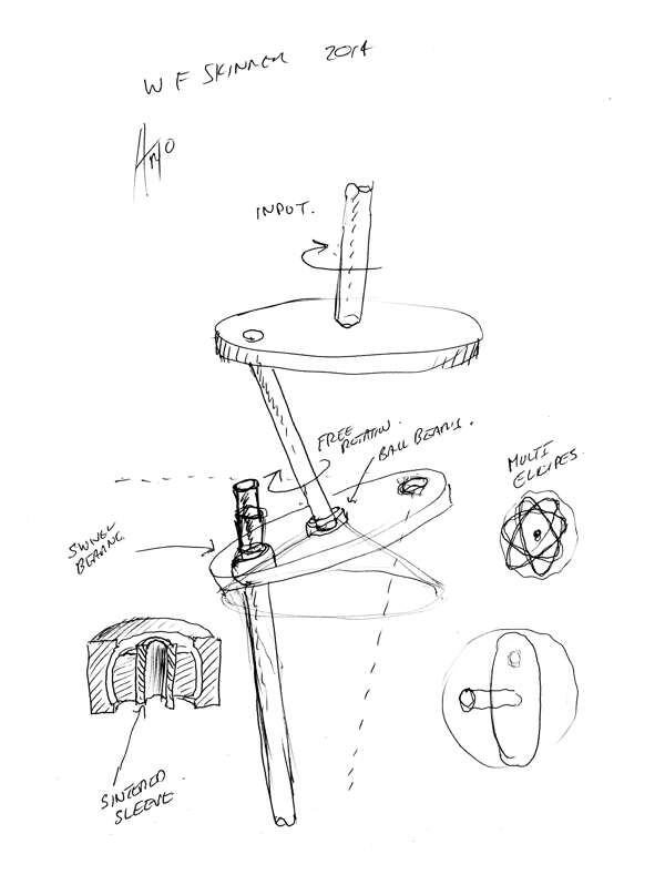
    What mechanism are you using for the input to the lever attached to the gimbal?

    Leave a comment:


  • Aaron
    replied
    input lever

    Originally posted by artoj View Post
    Hi Aaron, I have drawn an interesting combination, as you suggested, this particular type will definitely show chaotic tendency, multiple ellipses in a circular form, it could show harmonic tendencies of whole number elliptical rotations.

    Eltimple, nice work on your gimbals, I drew the Skinner gimbals as per video(+ or - 1/16"), any machine shop could make it, or even a good drill press and some flat bar and scrap steel also the bearings are available at QBC.

    It looks like everybody is enjoying a great learning experience, thanks William. Regards Arto.
    Arto,

    Where the images says "Free Rotation" it would still have a pivot there. The input wheel would be tilted and would be locked into place guaranteeing the top of the input lever traces the same ellipse every time.

    Leave a comment:


  • eltimple
    replied
    i have drawn up a dyno excell spreadsheet based on the Lindemann prony protocol..I could not actually find anything ro use so drew this up..link to my dropbox


    https://www.dropbox.com/s/781fzq359jocsy4/Dyno.xls

    if you have anything better let me know

    Leave a comment:


  • artoj
    replied
    Sketch

    Hi Aaron, I have drawn an interesting combination, as you suggested, this particular type will definitely show chaotic tendency, multiple ellipses in a circular form, it could show harmonic tendencies of whole number elliptical rotations.

    Eltimple, nice work on your gimbals, I drew the Skinner gimbals as per video(+ or - 1/16"), any machine shop could make it, or even a good drill press and some flat bar and scrap steel also the bearings are available at QBC.

    It looks like everybody is enjoying a great learning experience, thanks William. Regards Arto.

    Leave a comment:


  • eltimple
    replied
    well my gimbals could be scaled up, 4 x 1 inch flange bearings mounted on angle iron ( bolted together) then take the thing to a welder to weld all the bolts would not be much work...could all be done using a pilar drill with perhaps a 20 dollar tip to a mechanic to weld up in his lunch hour.

    Leave a comment:


  • Aaron
    replied
    gimbals and gimbal bearings

    Originally posted by eltimple View Post
    hopefully this will help people visualize

    Skinner gravity Engine Gimbals Part 5 - YouTube

    installed gimbals

    could use either of my pre built drive trains to run this but looking at ellipsoid
    Great demo! I didn't know it was called a gimbal - keeps things level like cameras, gyroscope instruments, etc...

    Started to search for gimbals online and found there are gimbal bearings - just what I need. Seems they're usually used in boat motors to keep the shaft in alignment and they have a lot more swivel action than the self-centering bearings I've been using.


    I can mount one of those on a wheel for the elliptical drive and can tilt the wheel quite a bit more than with the self centering bearings to get a narrow ellipse.

    Can also be used for the pivot point of the lever.

    One test I was using 3 super balls put in a triangle (as the pivot point) with the lever rod going through the middle. Gave me the range of motion needed and also was intrinsically spring loaded.

    Looks like a gimbal like what you made would give the most range on a wheel for an elliptical drive but I hope I can get away with just one of these bearings.

    Leave a comment:


  • Aaron
    replied
    elliptical motion

    Originally posted by goldpro View Post
    I built a crude version of the horizontal arm type and the short bar wouldn't
    always whip around as the longer bar was oscillated back and forth. Often it
    would just remain basically at right angles to the longer horizontal bar.

    I'm still not convinced that we need to move the lower end of the input lever shaft in an ellipse. Maybe the question to ask is what motion would serve us best?

    It seems to me the top of the bottom weight shaft (where it attaches to the translation coupler in a spherical bearing) moves in a circle through volumetric space (through the air). To try to confine it to an ellipse would
    require significant force that would always be fighting the centrifugal force
    of the lower, tall weight. That would lower the output of the whole machine.

    Therefore if the top of the bottom shaft moves in a circle, the translation coupler must move in a circle which means the bottom of the input lever rod
    must move in a circle. That means the top of the input lever rod must move in a circle. ?

    Trying to visualise it all is fun.... I think the lower weight's shaft lower pivot/bearing point (just above the gear but below the universal joint), and the x/y pivot point in the frame of the input lever rod must be lined up vertically so both the upper and lower weights are moving in circles in the air.
    The lower tip of the input lever rod and the upper end of the lower shaft would be drawing circles in the air but they would be different diameters.
    The translation plate would be doing some sort of dance around these 2
    pivot points.


    watching the videos it seems that my eyes and brain can see whatever motion of the top end of the input lever rod I want to see. I can see it moving in a clockwise circle. then if I play it again I can see it turning in a counter clockwise circle. then if played again I can see it oscillating back and forth. ???

    the above are just some musings on the workings of it all.
    I could be completely wrong.
    I sure am enjoying this discussion forum, thanks for almost everyone's helpful and insightful input.
    You bet this is getting exciting!
    Tom
    Tom,

    Instead of a short bar at the end of the horizontal shaft, would it work better if it was a wheel with the connection to the lever offset - like the little pulley I show in the video. I wasn't using it for that purpose but if that pulley was on the end of the horizontal bar and the lever was connected to where I have the self-centering bearing, it would serve the same purpose and might rotate easier?

    I believe elliptical absolutely serves us best. I don't think it is an issue of fighting the centrifugal force trying to maintain the ellipse. It is intrinsic in the mechanism to make that ellipse and its motion is limited by its relationship to the input lever's limits. There's like multiple positive feedback methods that are intrinsic to the whole machine.

    Leave a comment:


  • Aaron
    replied
    ellipse methods

    Originally posted by eltimple View Post
    see this video on elliipses starts at at 54 seconds

    https://www.youtube.com/watch?v=1v5Aqo6PaFw
    Yes, same concept. Looked around more but still can't find that anyone is actually using the wheel method.

    Those are all really cool - I like the wheel method like what I'm going with and the swing.

    I think the swing would make the most incredible piece of moving art and it would give the biggest gain since it does make use of gravitational potential energy. On a big unit with massive weights that don't have to move fast, the swing would be perfect. It would start to look like a Rube Goldberg machine at that point, but all the better. lol

    Leave a comment:


  • Aaron
    replied
    youtube

    Originally posted by shylo View Post
    Hi All, just got the video posted over at ou, if somebody wants to put it here their more than welcome. Here it just keeps saying failed to load maybe not enough room I don't know?
    artv
    Thanks Shylo, do you have a YouTube account you can post it to?

    Leave a comment:


  • artoj
    replied
    Simple graphic

    Here is a small video of an ellipsographic type mechanism with 2 axis, note the circle, broad ellipse, thin ellipse and the linear to and fro, all from the same mechanism. Regards Arto.
    Ellipse Guides - YouTube

    Leave a comment:


  • goldpro
    replied
    Originally posted by eltimple View Post
    hopefully this will help people visualize

    Skinner gravity Engine Gimbals Part 5 - YouTube

    installed gimbals

    could use either of my pre built drive trains to run this but looking at ellipsoid
    Thanks for that video! Great work.
    which motion best starts the top weight spinning?

    Leave a comment:


  • eltimple
    replied
    hopefully this will help people visualize

    Skinner gravity Engine Gimbals Part 5 - YouTube

    installed gimbals

    could use either of my pre built drive trains to run this but looking at ellipsoid

    Leave a comment:


  • goldpro
    replied
    I think the Murakami E.D. will work better than the idea of a horizontal
    bar that oscillates back and forth on a pivot with another short bar that pivots on it's end and "whips" around as Aaron laid out in one of the videos
    with the white graph paper pieces.
    I built a crude version of the horizontal arm type and the short bar wouldn't
    always whip around as the longer bar was oscillated back and forth. Often it
    would just remain basically at right angles to the longer horizontal bar.
    Keep in mind that we have to coordinate the rotating upper weights with each other in order to keep the forces balanced. Any given upper weight
    has to move in a manner exactly opposite to the one across from it on the machine or the whole thing will vibrate itself apart or across the floor.

    I'm still not convinced that we need to move the lower end of the input lever shaft in an ellipse. Maybe the question to ask is what motion would serve us best?

    It seems to me the top of the bottom weight shaft (where it attaches to the translation coupler in a spherical bearing) moves in a circle through volumetric space (through the air). To try to confine it to an ellipse would
    require significant force that would always be fighting the centrifugal force
    of the lower, tall weight. That would lower the output of the whole machine.

    Therefore if the top of the bottom shaft moves in a circle, the translation coupler must move in a circle which means the bottom of the input lever rod
    must move in a circle. That means the top of the input lever rod must move in a circle. ?

    Trying to visualise it all is fun.... I think the lower weight's shaft lower pivot/bearing point (just above the gear but below the universal joint), and the x/y pivot point in the frame of the input lever rod must be lined up vertically so both the upper and lower weights are moving in circles in the air.
    The lower tip of the input lever rod and the upper end of the lower shaft would be drawing circles in the air but they would be different diameters.
    The translation plate would be doing some sort of dance around these 2
    pivot points.


    watching the videos it seems that my eyes and brain can see whatever motion of the top end of the input lever rod I want to see. I can see it moving in a clockwise circle. then if I play it again I can see it turning in a counter clockwise circle. then if played again I can see it oscillating back and forth. ???

    the above are just some musings on the workings of it all.
    I could be completely wrong.
    I sure am enjoying this discussion forum, thanks for almost everyone's helpful and insightful input.
    You bet this is getting exciting!
    Tom

    Leave a comment:


  • eltimple
    replied
    Originally posted by Aaron View Post
    Here - one of my secrets I was testing a year ago on small scale, which essentially replaced the translation coupler with a pulley to cause the lower shaft to move in slightly elliptical orbit. The degree of the ellipse was limited to the angle that a self-centering bearing would allow for so I only was able to do a slight ellipse by tilting the input motor to drive the pulley. Ideally, it would be a pulsed motor pulsing when the shaft is at the ends of the ellipses.

    The translation coupler is best but again was just some tests I was doing.

    However, using the translation coupler and needing to move the upper part of the input lever in an ellipse, I will show what I think is the simplest method to DIRECTLY convert a circular motion in one plane to an elliptical motion in another plane. Others might be doing this concept in other applications but since I can't find it online, I'm calling it the Murakami Circular to Elliptical Converter or Murakami Elliptical Drive.

    I've never shown this before. I have gone back and forth over various ideas and tests in the last 1-2 years on all of this and I think this will make it easy for just about anyone to create the elliptical motion for the input lever in the most simple way...as long as we can get a self centering bearing or similar part that accomplishes what is in the video.

    Arto - you probably know exactly what is needed for this - it is pretty self-evident in the bicycle wheel demo that I do at the end of the video. After going back and forth through many ideas, this was actually the original concept I came up with and is why I have that pulley with the offset bearing in it because that is what I started with for testing quite a while back. The degree of elliptical-ness is determined by the tilt of the wheel...the more the tilt, the more elongated the ellipse. Do you know of a self centering bearing or something else that would give me 45 degrees tilt for example to give a serious ellipse?

    Here it is - hope you all like the concept. Murakami Elliptical Drive - https://www.youtube.com/watch?v=IbMUrY5MynA
    see this video on elliipses starts at at 54 seconds

    https://www.youtube.com/watch?v=1v5Aqo6PaFw

    Leave a comment:


  • turbogt16v
    replied
    you really should put some more effort in making the device,

    the weight are a little to far of the center,and also to light,
    the first and the second weight "must" move freely ,
    and to lever moves in elliptical orbit,

    Leave a comment:

Working...
X