Announcement

Collapse
No announcement yet.

My Asymmetric Electrodynamic Machines

Collapse
X
 
  • Filter
  • Time
  • Show
Clear All
new posts

  • Originally posted by HuntingRoss View Post
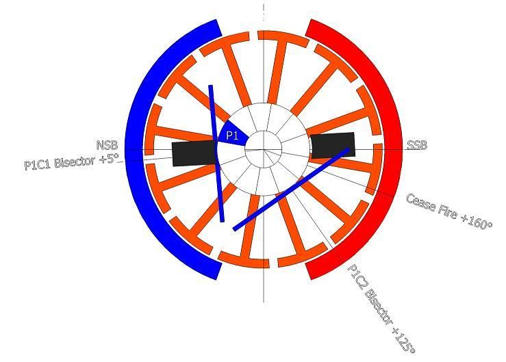
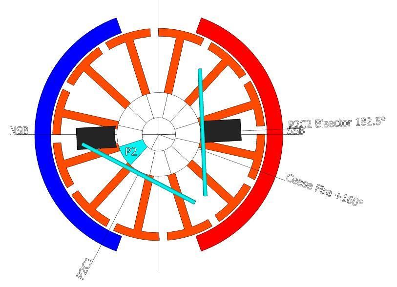
    The following images answer the ON/OFF timing angles for the 12 pole rotor wound as 4 pole pairs.

    [IMG][/IMG]

    Image 1 indicates P1 on the brush by 1° with the P1C1 coil 5° past the NSB. This is the 'ON' timing angle.

    [IMG][/IMG]

    Image 2 indicates the point at which P2 disconnects from the brush shown exactly at 0° disconnection. This is the 'OFF' timing angle.

    This places the P2C2 bisector at 2.5° past the SSB and 22.5° past the ideal 'cease fire' angle.

    Originally Posted by Ufopolitics View Post
    NOW, IF WE DO NOT FULLY DISCONNECT P2 & P16 BEFORE IT REACHES SOUTH STATOR BISECTOR...WE MUST DISREGARD THIS METHOD AND SWITCH BACK TO PREVIOUS OVERLAPPED METHOD, WHICH OFFERS MORE ADJUSTMENTS.
    The quote is for the 28 pole Imperial motor. For the purpose of the 12 pole motor, reference to P16 is irrelevant.

    The only conclusion to be drawn is...P2 DOES NOT disconnect until AFTER the SSB and therefore the 12 pole rotor 4 pole pairs CAN NOT be correctly timed.

    Hunting

    mark
    Ok, Mark,

    Now that you are so sure about the Four Pole Coils in the Pair NOT working good because of BAD timing...and after affirming it with my previous quoted text...

    Then I believe that by now you would realize why...the failure to perform of your previous model testing versus the OEM?

    The 'solution' was to overlap Coils in the Pair, like I wrote above...

    So, did you already built that new Overlapped version and test it?

    Would like to know the results...so we could all put this "page" behind...


    Regards


    Ufopolitics
    Principles for the Development of a Complete Mind: Study the science of art. Study the art of science. Develop your senses- especially learn how to see. Realize that everything connects to everything else.― Leonardo da Vinci

    Comment


    • question to anyone that knows -

      how do the various poles, of the steel armature, interact with a single winding ?

      does the contacting wire physically inject the metal with magnetism ? or does the coil just pulse by itself, and the amature does nothing ?

      Comment


      • Originally posted by JC4me View Post
        Hello UFO and Machine Alive,

        GoferParts.com is the distributor Imperial made me use for UFO Kit. Dyann did not respond, maybe because Gofer as their distributor is new. The 2012 UFO Kit prices have changed, or middle-man jacked-up, from $268 US to $445 US with 10-weeks lead time. July 15th delivery date.
        Hello JC4me,

        Oh man, I really hate when they do something like that!!...I am pretty sure some "good business man" had this "bright idea" to buy out this parts and re-sell them(with huge profit$ of course) ...taking it away from Imperial.

        That is a Jack up 'profit' of almost double from original price!!

        Factory motor new price, and itemized UFO Kit Parts line-items new prices coming tomorrow. I asked Nicky at Gofer for this today after weeping on the phone about the UFO Kit price Jolt. Friday i will call and get it in e-mail for the others who will follow your advice. Am I the only one to buy one since 2012?

        When i see how hard it looks to unwind, i surrender and painfully accept your advice to build this UFO Kit as "Easiest".
        Yes, I see...however, Dyann has given the MSRP or "List Price" for every single Item on this Kit...directly from the manufacturers (Imperial)...so, honestly...I would Insist on getting the same deal, or at least a 10-20% increase as Max...on top of established MSRP.

        Some of this parts like the Commutators are made in China...so, imagine the price they pay there for each when buying wholesale.

        This is a BIG motor. Along with this huge Imperial, I am wanting to learn about the 6KV generator for this thing you mentioned, to turn Bedini SG battery power back to usable AC, so i can put it to work.

        I will be reading until July 15th, and buying 5 LBS 16 AWG 200C Magnet wire. If you can, please post or PM small hardware details, like the woven insulator pasta, Stave-Sticks to hold windings in, Brush Cables, ("6 AWG", but are they 6 AWG 'Fine-Stranded Silicone Hobby Wire'?

        Thank you for your help

        -Ward

        Wow, stop there!
        ...a 16 awg was the OEM wire...but NOT GOOD for Asymmetric Winding!

        18 awg would be the right gauge friend...or finer than.


        Regards


        Ufopolitics
        Principles for the Development of a Complete Mind: Study the science of art. Study the art of science. Develop your senses- especially learn how to see. Realize that everything connects to everything else.― Leonardo da Vinci

        Comment


        • Simple old principle...

          Originally posted by grounded View Post
          question to anyone that knows -

          how do the various poles, of the steel armature, interact with a single winding ?

          does the contacting wire physically inject the metal with magnetism ? or does the coil just pulse by itself, and the amature does nothing ?
          Grounded,

          Whenever you wind a coil around any piece of ferromagnetic core and run electricity through the wires, the iron core WITHIN COIL magnetizes in a polarization defined according to the way you wound it...or the way you inject the voltage polarity.

          When the case of Motors...the Rotor Poles and Overlapped Coils...We turn them on one by one, so only the segment of core comprehended within the energized coil (in sequential turn) would be magnetized...

          In reality...if we could be able to just see the magnetic fields interacting in each turning Asymmetric Rotor...we would observe an almost STEADY magnetic field Pulsating in the firing designated timing angle related to Stators...while the iron core and coils keeps spinning, no matter the speed, and...the faster the spinning...the faster the pulses to the point it would show almost a steady Field...picture all this in your mind...if you could...

          Hope this helps...


          Ufopolitics
          Last edited by Ufopolitics; 05-09-2015, 04:23 PM.
          Principles for the Development of a Complete Mind: Study the science of art. Study the art of science. Develop your senses- especially learn how to see. Realize that everything connects to everything else.― Leonardo da Vinci

          Comment


          • Originally posted by Ufopolitics View Post
            Ok, Mark,

            Now that you are so sure about the Four Pole Coils in the Pair NOT working good because of BAD timing...and after affirming it with my previous quoted text...

            Then I believe that by now you would realize why...the failure to perform of your previous model testing versus the OEM?

            The 'solution' was to overlap Coils in the Pair, like I wrote above...

            So, did you already built that new Overlapped version and test it?

            Would like to know the results...so we could all put this "page" behind...


            Regards


            Ufopolitics
            Hi UFO

            I have been certain about this fact since this argument was fabricated by a certain participant on this thread.

            The two diagrams posted illustrate that certain participant knows 'DICK' about timing, and by calling the 12 pole '4 pole pairs' incorrect implied it was correctable. IT IS NOT correctable.

            You and I were seeking 'final agreement' and I conclude from your comments now, that we agree on the only outstanding issue...being, the angle for P2 to clear the brush MUST be included in the correct timing design for all motors.

            With regards to the 'failure to perform of [my] previous model testing'... I can confirm that none of those failures were due to the issue identified as inherent in the 12 pole '4 pole pairs' geometry.

            I have already (previously) agreed that 'lapping pairs' was the only salvation for the inherent flaw and, yes, I have built both 4 and 5 pole lapping pairs and they were not adequate to surpass the OEM.

            I have subsequently returned to and pressed ahead with 'lapping groups' as I have found them to be superior in every way.

            Testing results for my latest motors will be suppressed until fully completed.

            All I will add to this is my motor tests are now within 5% efficiency of the OEM motor which removes any criticism regarding my build quality and motor timing. The basis for comparison of test results is courtesy of Prochiro's horsepower and efficiency software which is an excellent piece of 'kit'.

            As a spoiler for future announcement...results indicate near parity on torque with much increased rpm against a falling (almost tolerable) power consumption compared to the OEM.

            Good Hunting

            mark

            Comment


            • Originally posted by HuntingRoss View Post
              Hi UFO

              I have been certain about this fact since this argument was fabricated by a certain participant on this thread.

              The two diagrams posted illustrate that certain participant knows 'DICK' about timing, and by calling the 12 pole '4 pole pairs' incorrect implied it was correctable. IT IS NOT correctable.

              You and I were seeking 'final agreement' and I conclude from your comments now, that we agree on the only outstanding issue...being, the angle for P2 to clear the brush MUST be included in the correct timing design for all motors.

              With regards to the 'failure to perform of [my] previous model testing'... I can confirm that none of those failures were due to the issue identified as inherent in the 12 pole '4 pole pairs' geometry.

              I have already (previously) agreed that 'lapping pairs' was the only salvation for the inherent flaw and, yes, I have built both 4 and 5 pole lapping pairs and they were not adequate to surpass the OEM.

              I have subsequently returned to and pressed ahead with 'lapping groups' as I have found them to be superior in every way.

              Testing results for my latest motors will be suppressed until fully completed.

              All I will add to this is my motor tests are now within 5% efficiency of the OEM motor which removes any criticism regarding my build quality and motor timing. The basis for comparison of test results is courtesy of Prochiro's horsepower and efficiency software which is an excellent piece of 'kit'.

              As a spoiler for future announcement...results indicate near parity on torque with much increased rpm against a falling (almost tolerable) power consumption compared to the OEM.

              Good Hunting

              mark
              Great to know your advances there Mark!

              Hope those 'Lapped Groups' are not referring to the single commutator structure...but to the fully Dual Comm Asymmetric Model...

              Hope to see those 'suppressed tests' released very soon!


              Take care


              Ufopolitics
              Principles for the Development of a Complete Mind: Study the science of art. Study the art of science. Develop your senses- especially learn how to see. Realize that everything connects to everything else.― Leonardo da Vinci

              Comment


              • Originally posted by Ufopolitics View Post
                Grounded,

                Whenever you wind a coil around any piece of ferromagnetic core and run electricity through the wires, the iron core WITHIN COIL magnetizes in a polarization defined according to the way you wound it...or the way you inject the voltage polarity.

                When the case of Motors...the Rotor Poles and Overlapped Coils...We turn them on one by one, so only the segment of core comprehended within the energized coil (in sequential turn) would be magnetized...

                In reality...if we could be able to just see the magnetic fields interacting in each turning Asymmetric Rotor...we would observe an almost STEADY magnetic field Pulsating in the firing designated timing angle related to Stators...while the iron core and coils keeps spinning, no matter the speed, and...the faster the spinning...the faster the pulses to the point it would show almost a steady Field...picture all this in your mind...if you could...

                Hope this helps...

                Ufopolitics
                yeah, perfect. thanks ufo.

                i thought it might be like this, charging the steel, but i wasnt sure, as my knowledge on electronic components is next to nothing.

                i can see why you wind like you do now, for maximum surface area, and a full, even pulse, across the section of poles.

                good stuff

                edit : have you tried wrapping a chain of several single poles before ?
                so that the single segments get a concentrated blast of magnetism ? (if it works like that)
                Last edited by grounded; 05-10-2015, 01:41 PM.

                Comment


                • Originally posted by Ufopolitics View Post
                  [IMG][/IMG]


                  [IMG][URL=http://s1251.photobucket.com/user/ufopolitics/media/ALL_NORTH_IMPERIAL%2056/REAL_IMPERIAL_MEASUREMENTS_zpsmm4lxpcn.png.html][/IMG]

                  That was absolutely all I needed to say or write here...


                  Ufopolitics
                  The first pic inaccurate. The brushes on the Imperial are the width of 2 commutator segments... Not 1 comm segment.

                  If possible, you need the correct critical angles with magnets and their bisectors showing. It will help future builders to understand.

                  Suggestion: 3 frames; P1 start, P1 middle and P1 disconnect... That will give a fuller picture of the critical angles.


                  Keep it Clean and Green
                  Midaz
                  Last edited by Midaztouch; 05-10-2015, 01:01 PM.

                  Comment


                  • Imperial P56 Two Diff Max Interact Angles

                    Hello to All,

                    Ok, below is something else I wanted to share here...it is a Diagram of Imperial Motor with Two Different Max Interaction Angles, just by a difference of an extra shared pole ...I chose to Fragment/Split the Rotor, since both arrangements apply to Two different winding types.

                    And secondly, my bad, the single Brush of Imperial does comprehend about Two Commutator Elements. It is corrected now, on Diagram below.

                    [IMG][/IMG]

                    In above Diagram I have chosen Five (5) Pole Coils in each Pair, since this is about overlapped coils. The main difference is about the spreading or contracting of Pair Bisectors by lapping with 2 or 3 poles shared or in common.

                    I have highlited in red the Max Interact Angles from starting Coil of "Entering" Pair (Repulse) to "Leaving"-end Coil from Second Pair (Attract) for both 'scenarios' displayed.

                    It is clearly seen that by just one rotor pole difference at intersection, creates a pretty considerable difference at final Max Interact Angles. (38.59º versus 50.83º)...but that is NOT ALL...

                    Note the 38º (left side) arrangement have All Four Bisectors VERY COMPACT, right next to each others, resulting in a very compact therefore strong Magnetic Field.

                    As in this contracted arrangement delivering a more compact field... We have much more play WITHIN the 90º Angle from N-S Stator Bisectors to search for the best timing.

                    I like this set up for Higher Torque...however, speed would be a bit slower than the 50º Angle at Right side of Graphic.

                    If You notice, the only difference of Total Poles Involved at this Max Interaction...is just One extra Pole. (8 to 9)...so the speed difference would be very small between both types.

                    We could reduce even more this lap winding by having up to Four Poles in common at Pairs...however...something start happening that may have some unpredicted results...Bisectors from Pairs start intersecting at same space...and until tested, we would not be able to tell if this would result in benefits or decrease of performance.

                    IMO, the left arrangement would be a very strong Machine...very flexible angle to Set Timing, searching for that "sweetest spot", without sacrificing torque because of such compact magnetic fields.

                    Only issue we may face here is "ROOM" to fit all required Pairs, since this would be a very 'populated' winding...meaning turns MUST BE VERY TIGHT.

                    The 50º winding type is much more "RELAXED"...since wider spread wires along rotor poles.


                    Regards to All


                    Ufopolitics
                    Last edited by Ufopolitics; 05-10-2015, 04:21 PM.
                    Principles for the Development of a Complete Mind: Study the science of art. Study the art of science. Develop your senses- especially learn how to see. Realize that everything connects to everything else.― Leonardo da Vinci

                    Comment


                    • Originally posted by Ufopolitics View Post
                      Hello to All,

                      Ok, below is something else I wanted to share here...it is a Diagram of Imperial Motor with Two Different Max Interaction Angles, just by a difference of an extra shared pole ...I chose to Fragment/Split the Rotor, since both arrangements apply to Two different winding types.

                      And secondly, my bad, the single Brush of Imperial does comprehend about Two Commutator Elements. It is corrected now, on Diagram below.

                      [IMG][/IMG]

                      In above Diagram I have chosen Five (5) Pole Coils in each Pair, since this is about overlapped coils. The main difference is about the spreading or contracting of Pair Bisectors by lapping with 2 or 3 poles shared or in common.

                      I have highlited in red the Max Interact Angles from starting Coil of "Entering" Pair (Repulse) to "Leaving"-end Coil from Second Pair (Attract) for both 'scenarios' displayed.

                      It is clearly seen that by just one rotor pole difference at intersection, creates a pretty considerable difference at final Max Interact Angles. (38.59º versus 50.83º)...but that is NOT ALL...

                      Note the 38º (left side) arrangement have All Four Bisectors VERY COMPACT, right next to each others, resulting in a very compact therefore strong Magnetic Field.

                      As in this contracted arrangement delivering a more compact field... We have much more play WITHIN the 90º Angle from N-S Stator Bisectors to search for the best timing.

                      I like this set up for Higher Torque...however, speed would be a bit slower than the 50º Angle at Right side of Graphic.

                      If You notice, the only difference of Total Poles Involved at this Max Interaction...is just One extra Pole. (8 to 9)...so the speed difference would be very small between both types.

                      We could reduce even more this lap winding by having up to Four Poles in common at Pairs...however...something start happening that may have some unpredicted results...Bisectors from Pairs start intersecting at same space...and until tested, we would not be able to tell if this would result in benefits or decrease of performance.

                      IMO, the left arrangement would be a very strong Machine...very flexible angle to Set Timing, searching for that "sweetest spot", without sacrificing torque because of such compact magnetic fields.


                      Regards to All


                      Ufopolitics
                      Can you add extra brushes to either designers to collect the collapsing field? I don't want to reduce the performance of the machine/magnetic drag.

                      Keep it Clean and Green
                      Midaz
                      Last edited by Midaztouch; 05-10-2015, 04:29 PM.

                      Comment


                      • Imperiall Structure

                        Hello to All,

                        I forgot to write on above Diagram that Generator Brushes (as Generating Pairs and related Comm Elements) are not included- meaning "painted", for sake of simplicity to just clearly explain about Motoring Actions.

                        It is well understood that Imperial is a Four (4) Brushes and Four Stators Structure.

                        Ufopolitics
                        Principles for the Development of a Complete Mind: Study the science of art. Study the art of science. Develop your senses- especially learn how to see. Realize that everything connects to everything else.― Leonardo da Vinci

                        Comment


                        • Originally posted by Ufopolitics View Post
                          Hello to All,

                          I forgot to write on above Diagram that Generator Brushes (as Generating Pairs and related Comm Elements) are not included- meaning "painted", for sake of simplicity to just clearly explain about Motoring Actions.

                          It is well understood that Imperial is a Four (4) Brushes and Four Stators Structure.

                          Ufopolitics
                          Thank you. That's very nice

                          BUT...

                          Can you ADD extra brushes to either designs to collect the collapsing field? I don't want to reduce the performance of the machine/magnetic drag.

                          In your opinion, is it possible to do what I'm saying? Because anything besides that would be a waste of time. Don't you agree!?

                          Midaz
                          Last edited by Midaztouch; 05-10-2015, 04:58 PM.

                          Comment


                          • Originally posted by Midaztouch View Post
                            Thank you. That's very nice

                            BUT...

                            Can you add extra brushes to either designers to collect the collapsing field? I don't want to reduce the performance of the machine/magnetic drag.

                            In your opinion, is it possible to do what I'm saying?

                            Midaz
                            As soon as P2 and P16 gets fully disconnected from Input, this coils would be in a kind of "limbo", where their previously oriented domains with North direction would get somehow in a 'loose status' just for nano seconds, then easily influenced by both South Stators Magnetic Fields...this would cause a Counter Orientation of the ferromagnetic comprehended core, which would be completely "compatible" with the natural collapsing field and Voltage polarity reversal.

                            We must realize that every time a ferromagnetic core approaches a magnetic field Pole, the field will "expand" and that specific Pole will take over that portion of the core under the inflluence.

                            IMO, at this early, primitive stage is too soon and too close to start collecting energy (by setting extra brushes), since it may create "Influence Conflicts" with the Coils being energized by direct input, since they are too close.

                            I recommend to set the Generator Brushes further away as possible from this 'conversion' stage, and as closer as possible before entering the next Input Cycle, this way we will 'suck out' all the reversed plus the induced energies, leaving a "Blank" clean Coil to receive next input, resulting in much less sparking.

                            However, all this are just assumptions based on magnetism and electrical behavior 'theories' as well as "not theories but reality", however, complex interactions requires that all of this must be tested/checked at different angles in order to determine which setting will deliver better performance and output.

                            Just my opinion.


                            Ufopolitics
                            Last edited by Ufopolitics; 05-10-2015, 05:20 PM.
                            Principles for the Development of a Complete Mind: Study the science of art. Study the art of science. Develop your senses- especially learn how to see. Realize that everything connects to everything else.― Leonardo da Vinci

                            Comment


                            • Originally posted by Ufopolitics View Post
                              As soon as P2 and P16 gets fully disconnected from Input, this coils would be in a kind of "limbo", where their previously oriented domains with North direction would get somehow in a 'loose status' just for nano seconds, then easily influenced by both South Stators Magnetic Fields...this would cause a Counter Orientation of the ferromagnetic comprehended core, which would be completely "compatible" with the natural collapsing field and Voltage polarity reversal.

                              IMO, at this early, primitive stage is too soon and too close to start collecting energy (by setting extra brushes), since it may create "Influence Conflicts" with the Coils being energized by direct input, since they are too close.

                              I recommend to set the Generator Brushes further away as possible from this 'conversion' stage, and as closer as possible before entering the next Input Cycle, this way we will 'suck out' all the reversed plus the induced energies, leaving a "Blank" clean Coil to receive next input, with much less sparking.

                              However, all this are just assumptions based on magnetism and electrical behavior 'theories' as well as "not theories but reality", however, complex interactions requires that all of this must be tested/checked at different angles in order to determine which setting will deliver better performance and output.

                              Just my opinion.


                              Ufopolitics
                              With the Singular Coils = A1MoGen, I believe that you can add extra brushes to collect the collapsing field... There is plenty of room to add the extra brush with no interface.

                              Look at the CAD. They fit and with with room to find that "Sweet Spot". Don't you think so!?

                              Midaz
                              Attached Files
                              Last edited by Midaztouch; 05-10-2015, 05:23 PM.

                              Comment


                              • Originally posted by Midaztouch View Post
                                With the Singular Coils = A1MoGen, I believe that you can add extra brushes to collect the collapsing field... There is plenty of room to add the extra brush with no interface.

                                Look at the CAD. They fit with with room to find that "Sweet Spot". Don't you think so!?

                                Midaz
                                Re read my previous post as I have edit it.

                                It must be tested.

                                The best answer to any questions is only found through real testing.
                                Principles for the Development of a Complete Mind: Study the science of art. Study the art of science. Develop your senses- especially learn how to see. Realize that everything connects to everything else.― Leonardo da Vinci

                                Comment

                                Working...
                                X