Announcement

Collapse
No announcement yet.

Transformer Core of Capacitor plates

Collapse
X
 
  • Filter
  • Time
  • Show
Clear All
new posts

  • #16


    Uploaded with ImageShack.us

    Power supply is via a DC convertor. 9.75V @ 1.5A. The supply has an AC leakage of 4.5V @ 0.3mA when measured against a ground on either lead from the PS. No AC present when tested from both leads.

    output measurements as follows.

    22.20 VAC
    46.58 VDC

    attaching a 12v 21W 1156 bulb to the PS side changes the voltage thusly:

    21.88 VAC
    49.82 VDC

    this circuit will charge a capacitor to 70V, lights neon bulbs.

    tried to measure amp draw on the PS side when charging a cap and neon bulb and there is no measurable draw. putting the bulb on the PS leads shortens the time it takes to charge a capacitor.

    the ground lead is responsible for the voltage, no ground lead and voltage drops signifigantly.
    disconnecting the lead from the negative terminal to windings and ground lead the V points measure 4.54VDC and 1.97VAC, putting the bulb on the PS side the voltage increases steadly but slowly.

    The circuit draws strongly from the earth ground, a 16sq/ft foil surface wrapped in 3mil poly acts a virtual 'antennae' ground and voltages are lower by about 15VDC and ~18VAC.

    interesting to note, it's difficult to measure the voltage, as it is dependent on load. just the terminal ends reads a maximum of 48V putting a capacitor across the terminals the voltage increases to 70V however it will light a 120V neon bulb.
    Last edited by madhatter; 05-23-2012, 06:56 AM.

    Comment


    • #17
      the windings are .017" 25awg enamel magnetic wire parallel wound series connected bifilar. total of 17 turns.

      Comment


      • #18
        just adding a few notes...
        total wire length is 10'

        this is an unbalanced circuit, as the capacitor plates are odd numbered there is going to be a miss match in the dielectric charge, this in-turn pulls from the ground. with the ground being on the load side the load is now in the circuit and needs to be balanced as well.

        70v is the maximum so far at 60Hz.

        need to adapt a number of capacitive equations and develop some capacitive inductive equations to model this.

        core field strength is ~480 uT

        Steinmetz capacitive M inductance equations with given results predicts a 0.8 T field to achieve the voltages given.

        Comment


        • #19
          Very interesting, May I make a suggestion?

          Separate the circuit for giggles. Create a tank circuit out of the primary winding and a separate inductor. Drive this at resonance. Now place a DC current through the secondary winding. Place your scope probes across the secondary. Now you can see if the effect of charging and discharging the capacitive plates affects the transformer operation. If it changes the permeability of the core, you will get a parametric oscillation, and you may see a wiggle on the scope probe of 2x the frequency of the tank circuit created by the primary and separate inductor.


          Just a thought.....

          Comment


          • #20
            Originally posted by Armagdn03 View Post
            Very interesting, May I make a suggestion?

            Separate the circuit for giggles. Create a tank circuit out of the primary winding and a separate inductor. Drive this at resonance. Now place a DC current through the secondary winding. Place your scope probes across the secondary. Now you can see if the effect of charging and discharging the capacitive plates affects the transformer operation. If it changes the permeability of the core, you will get a parametric oscillation, and you may see a wiggle on the scope probe of 2x the frequency of the tank circuit created by the primary and separate inductor.


            Just a thought.....
            I know that the charge cycle on the plates effects the windings, in a sense this is a tank circuit as the primary windings are the plates and the secondaries are the windings around the core.

            got a scope tonight, going to setup and start again tomorrow.

            Comment


            • #21
              got the scope up and running yesterday, odd results. One of my probes is not working as it should, need to fix that.

              putting a DC charge on the plates then overlaying it with an AC signal is very effective. Still having a dickens of time getting an ampre draw reading on capacitor plates when in operation. I'll try a couple other things today, last resort is to go get one of those wall plug meters and use that.

              One big issue is near field capacitance, and the voltage spike. The latest prototype hums at 120Hz or twice the plates. a cap and neon bulb will resonate based on the std parameters although it's when the bulb is just about to flash there is a MASSIVE voltage spike that the meter chirps a warning on uS before the flash. the scope picks it up with the probe laying about 12" away.

              I'm also not comfortable with the floating differential measurements, as the ground significantly increases voltage.

              Comment


              • #22
                plugging away, well the cores don't last long. shorting and arcing over to the windings is becoming a problem. need to move up to borosilicate glass and probably silicone or ptfe insulated wire.

                back to work...

                Comment


                • #23
                  new core design,interesting result. Taking the B field of a capacitor and optimizing a layout to work in this strange circular field I came up with a log periodic array. I put together a simple 2 sector prototype, not calc'd just rough. It's the most effective layout so far.

                  did a quick layout in cad and will need to work on the calcs for the series. a number of parameters to account for, size, frequency, pulse duration, field intensity.

                  Eric if you're reading this it falls directly into your post on the log periodic. What I'm wrestling with though is the time variant or invariant electrostatic field movement that induces the magnetic field in a capacitor.


                  I'm still surprised by the simplicity of this and that is does indeed work. OK simple is relative, there is a surprising amount of calculations needed to make it efficient, but it's still simple enough.


                  Uploaded with ImageShack.us

                  Comment


                  • #24
                    9' of 0.017" wire wound in the star pattern, log periodic spacing. ends up with 4 turns per pattern. one wire lead out.

                    output is 28 VDC.

                    it's seems to be a type of electrostatic generator, going to build a bank and see if I will increase the voltage.

                    A mineral oil bath added 5 volts to the efficiency.

                    Comment


                    • #25
                      experiment and research, well during the research phase of this it's developed into where this phenomenon is known as 'displacement current'. This is where is gets complex, very complex. The missing 'J in Maxwell's modified Ampere law.

                      Comment


                      • #26
                        Originally posted by madhatter View Post
                        9' of 0.017" wire wound in the star pattern, log periodic spacing. ends up with 4 turns per pattern. one wire lead out....
                        Hi madhatter,
                        Thanks for all the updates on this interesting topic.
                        If you can post the odd photo, every now and then, so that I can get a better idea of the setups,that would be great.

                        PS: I am dunking my "replications" into the air core of excited coils and try to "see what gives".
                        Attached Files

                        Comment


                        • #27
                          been busy working away on the calculations and equations. So far I'm at where something doesn't add up, no surprise really.

                          The voltages I'm getting are much higher than the math suggests, more research is needed.

                          I also wonder about lenz's law in this case as well.


                          Comment


                          • #28
                            Hi madhatter,
                            thank you for the photos.
                            So you place the flat star winding in the electric field between two capacitor-plates ?
                            Which basically gives you the following 5-layer sandwich:
                            Code:
                            top layer:    iron washer
                            below that:   copper plate 
                            below that:   flat star winding
                            below that:   copper plate
                            bottom layer: iron washer
                            Is my understanding correct?
                            Last edited by marxist; 06-02-2012, 03:51 AM.

                            Comment


                            • #29
                              Originally posted by madhatter View Post
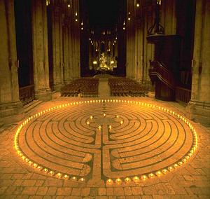
                              Interesting. This reminds me of something I noticed, I think watching some TV documentary on something relating to religion/churches/cathedrals and being cynical of all the "innocent" religious/masonic symbolism and all that propaganda type stuff, they showed a pattern on a floor which I thought through reason of my views on the use of symbolism might make an interesting coil. After some google image search and narrowing it down to the terms "Notre Dame floor" or "Labyrinth Notre Dame":


                              [edit] Centre of the square cornered one

                              http://3.bp.blogspot.com/-3Nqy3-Wm9G...Q/s1600/31.jpg

                              Last edited by dR-Green; 06-02-2012, 04:40 AM.
                              http://www.teslascientific.com/

                              "Knowledge is cosmic. It does not evolve or unfold in man. Man unfolds to an awareness of it. He gradually discovers it." - Walter Russell

                              "Once men died for Truth, but now Truth dies at the hands of men." - Manly P. Hall

                              Comment


                              • #30
                                Originally posted by marxist View Post
                                Hi madhatter,
                                thank you for the photos.
                                So you place the flat star winding in the electric field between two capacitor-plates ?
                                Which basically gives you the following 5-layer sandwich:
                                Code:
                                top layer:    iron washer
                                below that:   copper plate 
                                below that:   flat star winding
                                below that:   copper plate
                                bottom layer: iron washer
                                Is my understanding correct?
                                Yes, it's a flat steel washer. I'm going to replace that with plexi tommorow as I want to remove any ferromagnetic fields.

                                Comment

                                Working...
                                X