Announcement

Collapse
No announcement yet.

Mosfet Heating Circuits

Collapse
X
 
  • Filter
  • Time
  • Show
Clear All
new posts

  • #76
    Hi everyone,

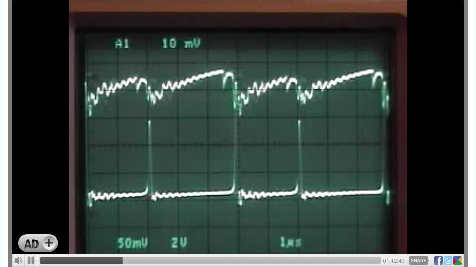
    This post is a recap of a "LIVE" recording at "Open Source Research and Development" channel which was a 5-hour non stop recording on January 24, 2010 using a Tektronix 2445A Oscilloscope.

    Please see the Image time bars for actual recorded time in hours, minutes and seconds.

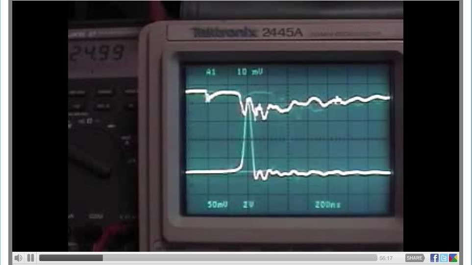
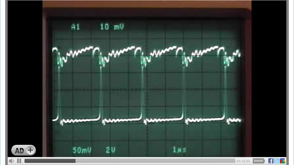
    Channel 1 - Mosfet Source Pin 50 Mv (x10)
    Channel 2 - 24 Volt Battery Bank 2 V (X10)


    Scope Trigger - Channel 1 (A1) "FALLING" signal slope [ \ ] "IMPORTANT"

    "START"

    First the 12 Volt battery was connected to 555 timer circuit "only" and pre adjusted, the "ON" potentiometer to minimum resistance (0), the "OFF" potentiometer adjusted to maximum resistance (2K), resulting duty cycle is at about 21.48 %

    Second the 24 Volt battery bank is connected, The circuit now defaults to a 50 - 55 % duty cycle, no further "ON" or "OFF" potentiometer adjustments are needed. Then by adjusting the "GATE" potentiometer "only" using the oscilloscopes 200ns division for minimum Mosfet source Mv and two (2) divisions from the "OFF" signal to the 24 Volt Battery signal "spike" combined with the Fluke 87 DMM highest voltage reading connected to the 24 volt battery bank.

    The device circuit is 100 % fully functional in the preferred mode of operation and under "load" the 24 Volt Battery bank.

    Voltage is now at 25.00 DC Volts with no further adjustment to be made on any of the circuit potentiometers.
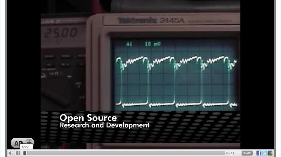


    A now recorded 24 Volt battery bank voltage increase seen on the Fluke 87 from the starting voltage of 25.00 to 25.01 DC volts.
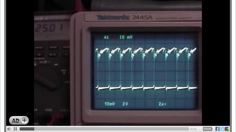
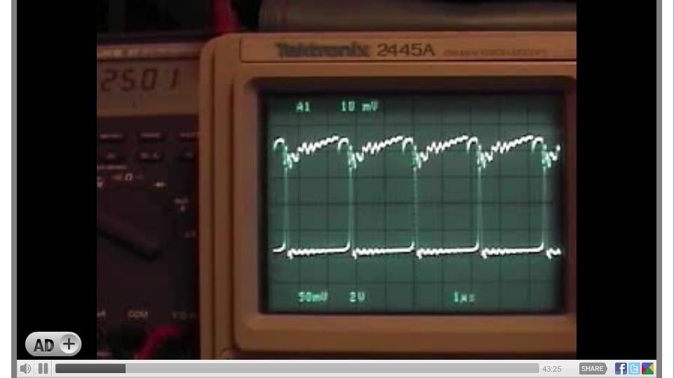

    A look at all the circuit components and temperature readings of the Load Resistor, Mosfet and Shunt Resistor.
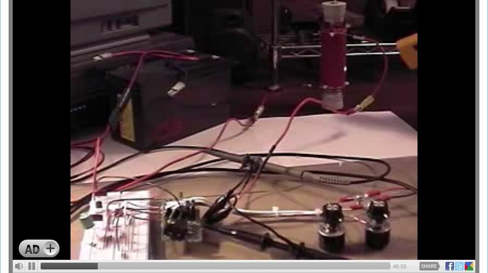
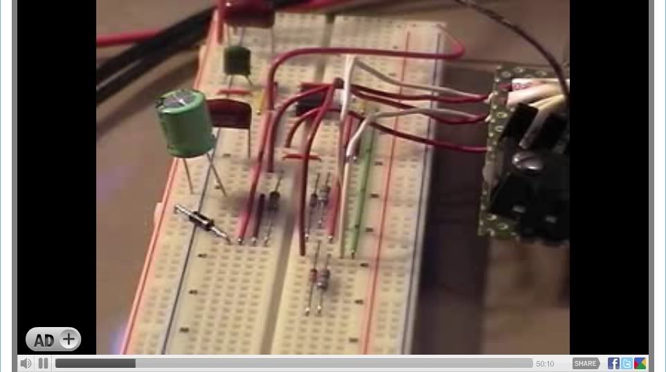


    The oscilloscope at the 200ns division selection with two (2) divisions from the Mosfet source "OFF" signal to the 24 Volt Battery signal "spike" combined with the Fluke 87 DMM highest voltage reading connected to the 24 volt battery bank.

    The oscilloscope at the 1us division in the circuits preferred mode oscillating normally


    "FINISH"

    Now after approximately 5-hours of continuous operation the 24 Volt battery bank voltage has dropped from the Starting voltage of 25.00 to 24.88 Volts DC, a total decrease of .12 Volts DC under load, maintaining a 140 to 145 + degree F temperature on the "Load Resistor" which is about 5.5 watts continuous load.



    Best Regards,
    Glen
    Last edited by FuzzyTomCat; 05-04-2010, 01:50 AM. Reason: clearity of description
    Open Source Experimentalist
    Open Source Research and Development

    Comment


    • #77
      Back To Basics - Part 3 : The Other Half Of The Transaction

      Hi Guys,


      I have the utmost confidence that those following my last two post regarding questions for Test #13 will have realized that so far I have only covered half of the AC transaction - the positive half of the cycle. So far we have discussed the dissipated power in the load resistor that we can attribute to battery power being delivered to it. However, we all know that there is more to the story. We have 9.14 volt-amps of apparent power involved that we really haven't given a fair hearing.

      We know, that after a period of time that the MOSFET is in the ON condition, that conventional DC current flows through the load resistor and if allowed to continue long enough, that resistor will charge magnetically in the inductive winding it possesses. This means that it becomes a DC solenoid and a magnetic field surrounds it with a B vector running straight through its center lengthwise.

      How long does it take to build the field and how much energy is stored in the field?

      There is a relationship between the electrical current and the building of the magnetic field. At time zero (0t) when we first turn on the MOSFET, 100% of the current is not yet flowing. At time one (1t), 63.2% will be flowing, leaving 36.8% not yet flowing. At 2t, an added 63.2% of the remaining 36.8% will be flowing leaving 13.54% of the overall current not yet flowing. At 3t, an added 63.2% of the remaining 13.54% will be flowing, leaving 4.98% not yet flowing. At 4t an added 63.2% of the remaining 4.98% will be flowing, leaving 1.83% not yet flowing. And finally at 5t an added 63.2% of the remaining 1.83% will be flowing, leaving 0.675% not yet flowing. So, after 5t we find that our current is flowing at 99.33% of its total value - therefore we generally consider an inductor to be fully charged after 5 time constants. You can go to infinity and it will never reach 100% because each addition of current flow is always 63.2% of the remaining amount. The formula for the forgoing is It = E/R (1 - e ^ (tR / L) where e is the natural log constant 2.71828. This resolves down to each time constant, t = L / R seconds. This is good for us, because we know the R = 9.73 ohms from Glen's Baseline profile test and we know the L in Henries from Back To Basics Part 2Energy Stored in an Inductor

      Energy Stored in an InductorSo if we are operating at 426kHz, how long do we have DC current building the field?The BEMF seeks to distribute itself evenly throughout all the conductors connected to it. In this case, the conductors become charged evenly (given the time to fully distribute).

      So how much voltage would we expect in the BEMF pulse?
      Interestingly, this depends on how fast the field is allowed to collapse and how much energy is stored in the field. We can use this formula: E = -NdΦB / dt where N is the number of turns (48) and ΦB is the flux density in Webers and E How much real dissipated power can we expect from the BEMF Spike?62.08W. Is that real power? Yes, but it is peak power of a sinus waveform and is reduced to zero watts over a 100ns period. So the RMS value would be 0.707 ∙ 62.08 for that 100ns period, or 43.89W. 4.47WWhere does the extra watt come from?
      "Amy Pond, there is something you need to understand, and someday your life may depend on it: I am definitely a madman with a box." ~The Doctor

      Comment


      • #78
        H, Glen this is brilliant info, i have already started putting a video production as thank you and quick start for this, the open source community really owes you guys a MASSIVE DEBT.

        Thanks so much for these posts guys.

        Ash

        Comment


        • #79
          Hi everyone,

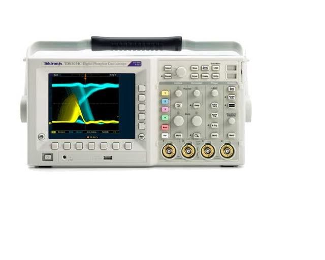
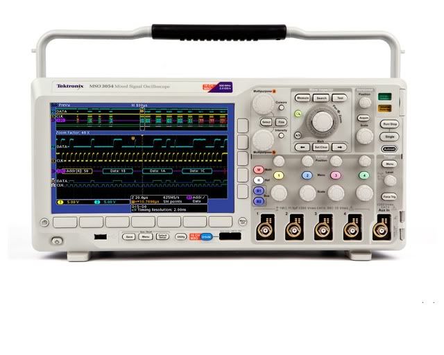
          These are the oscilloscopes I used on my Videos, testing and evaluation of this circuit so far ....

          TESTS #1 through TEST #15

          Model - Tektronix TDS3054C
          Bandwidth - 500 MHz
          Sample Rate - 5.0 GS/s
          Record Length - 10 k
          Channels - 4


          TDS3000C Digital Phosphor Oscilloscope Series > Products : Tektronix
          Tektronix TDS 3054C - Operation Manual and Specifications - PDF


          TESTS #16 through TEST #22

          Model - Tektronix DPO3054
          Bandwidth - 500 MHz
          Sample Rate - 2.5 GS/s
          Record Length - 5 M
          Channels - 4


          MSO/DPO3000 Mixed Signal Oscilloscope Series : Tektronix
          Tektronix DPO 3054 - Operation Manual and Specifications - PDF


          Model - Tektronix 2445a
          Bandwidth - 150 MHz
          Channels - 4

          Tektronix 2445A - Operation Manual and Specifications - PDF

          Glen
          Open Source Experimentalist
          Open Source Research and Development

          Comment


          • #80
            Hi Harvey,
            Thank you for your detailed reply to my
            I have to thank you for very gently pointing out to me that my coil is part of a capacitor discharge system - this is now glaringly obvious to me, and I have spent some time in the last two days trying to talk to the right engineer at Evinrude/Johnson to get the data on this component -with no result.
            The motor it came from had a separate cdi module, so I automatically assumed that the cap was in the module, and that the coil was just a coil. Another of my litany of mistakes.There must be some cap inside it. I turned the diode around, and the on time of the spark gap increased substantially [more power ,as you predicted], but the ringing was very much less, and its the ringing thatI am interested in. The capacitative spike disappeared except for the shoot thru .The Tau is very evident in the decay of the ringing.
            To get back on topic - the circuit you drew for me, was my effort to to find out what happens to the body diode in a mosfet heater circuit.
            I use a circuit very similar to the one discussed here.I have a lot [20years] of practical experience with liquid lead acid batteries, and I reckon that the batttery is a fundamental part of the cicruit. You will not get the effect with a power supply. A liquid lead acid battery has low impedance and is capable of resonance - look at the ringing in the battery voltage in Glen`s fantastic scope shots. A liquid lead acid battery is not amenable to a strict mathematical analysis - a few crystals of PbSO4 fall off a plate during discharge, and suddenly you have increased voltage. To the knee in the discharge curve , you can use voltage as a guage of state of charge, - but I have yet to find it a straight line.I regularly discharge batteries from 12.8v to10.8v and the specific gravity of each cell will have dropped from 1.26 to 1.24 during the discharge, and if left unrecharged for 2 hours, will drop to 1.22 while the voltage will have risen to 11.8 at least. A lot of people cannot understand that a battery @11.8v is dead flat!
            Also, pulse charging is definitely more efficient than brute force DC charging, where a lot of energy is wasted as heat.

            I think that if you can match the resonant frequency[ or a sub division of it] of an inductive resistor, to the resonant frequency of a battery, - there can be effects worth looking at.
            I do this with large batteries [100Ahr] @ low frequency. I keep a radio 2 feet away from the resistor, and when it starts squealing, I know I am getting near - and then the mosfet fries.- I have fried over 50 mosfets, and I blame the body diode. And yes, I know i am operating the mosfet way beyond its ratings, but I reckon the diode cannot handle the energy being bounced off it.
            Glen, I would like to ask you if, once you hit your "sweet spot",do you have difficulty in maintaning it, as the resistor rises in temperature? It does not seem so from your description of start-up. You are operating at a much higher frequency than me , which may give greater stability.
            All I want is a switch that can handle vast power, reversals of polarity, at any frequency - is that too much to ask!? Sooner or later, my large IGBT will be called to the frontline, but not before I think it has a fighting chance - it has a body diode too.
            Another effect, before the mosfet fries, is that my mobile phone will switch off from over 20 feet away, and this worries me . I want shielding, but from what? -RF ? Microwave? X-Ray!? - of course ,if infra red is a large part , then we are in business!
            Chris

            Comment


            • #81
              is
              "Amy Pond, there is something you need to understand, and someday your life may depend on it: I am definitely a madman with a box." ~The Doctor

              Comment


              • #82
                Hi everyone,

                I don't want anyone to think that work on this circuit has stopped ....

                We are now in a long waiting period for any actual or credible circuit "replications" to be constructed and help verify the detailed data and video findings that has already been done by Harvey and myself.

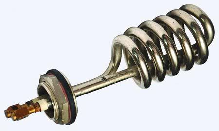
                There is several actual applications using other "resistive" load devices that are being looked at for any possible use that could be of benefit using the circuit modified even further for higher wattage applications with new technology on experimental items such as Oxyhydrogen ( HHO ) production to off the shelf items such as this "water heating" element.


                Best Regards,
                Glen
                Open Source Experimentalist
                Open Source Research and Development

                Comment


                • #83
                  Wow, that is shiny and new - very nice

                  Are their any specs as to the inductance or is that just purely a resistive type element?

                  I guess what I am asking is; can that style somehow resonate in the desired frequency range? It looks like it would be made for a low frequency like 50 or 60 hertz but I would need the sizes to be sure.

                  I really like the design you show here where the one lead runs through the center of the coil - I've seen others where it runs outside and that just seems so unbalanced and problematic.

                  Great Stuff
                  "Amy Pond, there is something you need to understand, and someday your life may depend on it: I am definitely a madman with a box." ~The Doctor

                  Comment


                  • #84
                    Good work

                    Originally posted by FuzzyTomCat View Post
                    Hi everyone,

                    I don't want anyone to think that work on this circuit has stopped ....

                    We are now in a long waiting period for any actual or credible circuit "replications" to be constructed and help verify the detailed data and video findings that has already been done by Harvey and myself.

                    There is several actual applications using other "resistive" load devices that are being looked at for any possible use that could be of benefit using the circuit modified even further for higher wattage applications with new technology on experimental items such as Oxyhydrogen ( HHO ) production to off the shelf items such as this "water heating" element.


                    Best Regards,
                    Glen

                    Your work is always given at 100%.
                    Thank you


                    TheTruthBeKnown

                    Comment


                    • #85
                      Originally posted by Harvey View Post
                      Wow, that is shiny and new - very nice

                      Are their any specs as to the inductance or is that just purely a resistive type element?

                      I guess what I am asking is; can that style somehow resonate in the desired frequency range? It looks like it would be made for a low frequency like 50 or 60 hertz but I would need the sizes to be sure.

                      I really like the design you show here where the one lead runs through the center of the coil - I've seen others where it runs outside and that just seems so unbalanced and problematic.

                      Great Stuff
                      Hi Harvey,

                      I haven't gotten the full specifications from the manufacture yet but it is a 240 volt 1000 watt unit and I'm trying to find a lower voltage product with the same element configuration. Hopefully it would be something that's "off the shelf" and not custom built which would be preferred and still using the modified circuit to drive the "resistive" element upgraded for the loads connected.

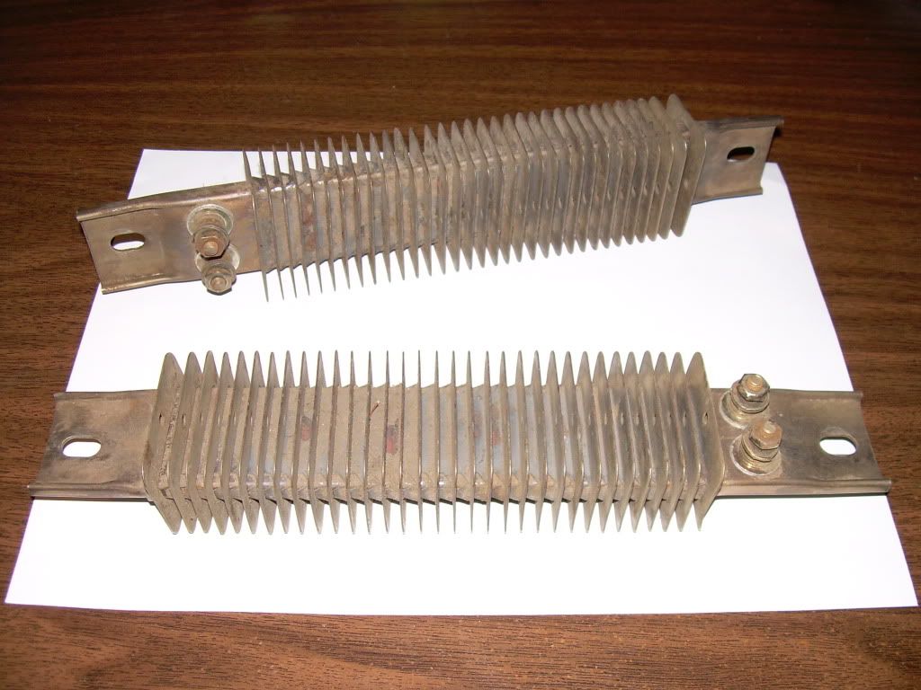
                      Here is another "resistive" element (used needing a good cleaning) which is a finned strip heater, these are 20 ohm, 120 volt, 725 watt, stainless steel, 925 degrees F. maximum temperature.


                      Industrial Heaters, Controls, Heat Tracing - Chromalox
                      Vulcan: Heaters - Metal Sheath

                      I'm still acquiring some components to duplicate the modified circuit and device used in all the Tests 1 through 22, so I can keep the "original" intact for any possible future use.

                      Best Regard's
                      Glen
                      Open Source Experimentalist
                      Open Source Research and Development

                      Comment


                      • #86
                        Is Ok For Current MOSFET

                        Hi Glen,

                        At 1000W, we are still well within the voltage and amperage limits of the IRFPG50 on that element because the Amperage would only be about 4.2A. That is the advantage of using the 240V

                        The problem, in a battery powered system, is to boost the battery voltage to 240V in a 1kW configuration. Of course the simple answer would be 20 batteries in series and that is not all that far-fetched in real world applications I have seen.

                        However, a 1kW Inverter could be used as well but such approaches inevitably add unwanted losses to the system.

                        Another approach would be to use a voltage multiplier front end that typically has lower losses associated with it compared to the inverters. Of course a single 700Ah car battery would only give you about 8 hours of operation before needing to be recharged if it were feeding a 1kW heater.

                        I installed a 120VAC Hott Rod
                        "Amy Pond, there is something you need to understand, and someday your life may depend on it: I am definitely a madman with a box." ~The Doctor

                        Comment


                        • #87
                          Hi Everyone,

                          Just thought I would share this with any who would like to keep the heat in their element instead of in the MOSFET:


                          This is a relatively high amperage part with an extremely low on resistance.

                          Cheers!


                          "Amy Pond, there is something you need to understand, and someday your life may depend on it: I am definitely a madman with a box." ~The Doctor

                          Comment


                          • #88
                            Modified circuit

                            Hi guys can you post the latest circuit for a 1000w or 2000w heater?
                            Thanks

                            Comment


                            • #89
                              Originally posted by Guruji View Post
                              Hi guys can you post the latest circuit for a 1000w or 2000w heater?
                              Thanks
                              Hi Guruji,

                              The circuit is basically the same, but the voltage needs to be increased while keeping the amperage the same.

                              The IRFPG50 can tolerate upto 1000V before it goes into avalanche. As long as the current is kept at 6A, the MOSFET thermal dissipation will not change because the internal resistance of the MOSFET is always about 2 ohms when fully powered and the voltage drop across that will be the same for a given amperage.

                              So, the target configuration will be a 2kW heater at 6A and the necessary supply voltage for that power dissipation. The net impedance will need to be about 55.55 Ohms and the voltage will need to be about 333.33V.

                              So, let's imagine 6 of Glen's resistors in series and a 3kW power supply at 360V. This gives a practical current of 6A and 2.16kW of output power.

                              How do you get a 3KW supply?

                              Imagine if you had 10 of these in series: 36V 30AH V2.5 LiFePO4 Battery Pack

                              These batteries have a through current of 30A continuous and 2100W by themselves. So 10 gives you twenty one thousand watts of power available or the ability to run a 2kW heater for about 10 hours straight.

                              So the only real changes you need to make to Glen's Modified circuit is to ensure the electrical paths can handle the 6A and 360V. Of course the duty cycle is only about 50%, so the actual room heating from the dissipation will be half as far as true BTU's go and the actual battery drain will be 20 hours instead - maybe . . . it all depends on that aperiodicity - the real BTU's could be drastically less if the average dissipation is less than 50% depending on the integrated spike area and dissipation of that spike into the load.


                              EDIT: I made an error in those calcs - the battery capacity is 1200W not 2100W - you may wish to adjust my calcs accordingly.
                              Last edited by Harvey; 07-17-2010, 12:26 AM.
                              "Amy Pond, there is something you need to understand, and someday your life may depend on it: I am definitely a madman with a box." ~The Doctor

                              Comment


                              • #90
                                Originally posted by Harvey View Post
                                Hi Chris,

                                If I have the layout in my mind correctly, and looking at your pic, does this look like what you have there?

                                The Ozmatic Schematic

                                The Ozmatic Schematic RevA


                                Hi Harvey you're reffering to these posted schematics when you said circuit is basically the same?
                                Thanks

                                Comment

                                Working...
                                X