Announcement

Collapse
No announcement yet.

Mosfet Heating Circuits

Collapse
X
 
  • Filter
  • Time
  • Show
Clear All
new posts

  • FuzzyTomCat
    replied
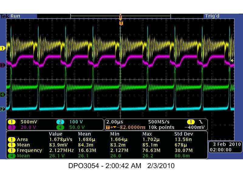
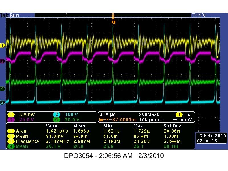
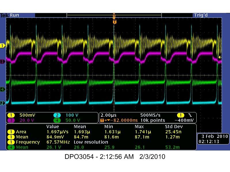
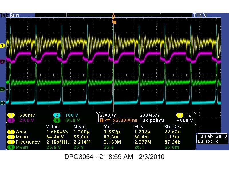
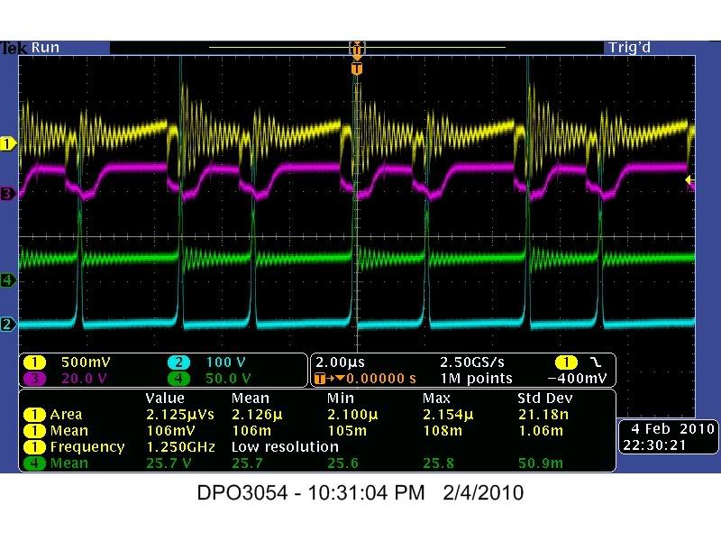
    Test #22

    Hi everyone,

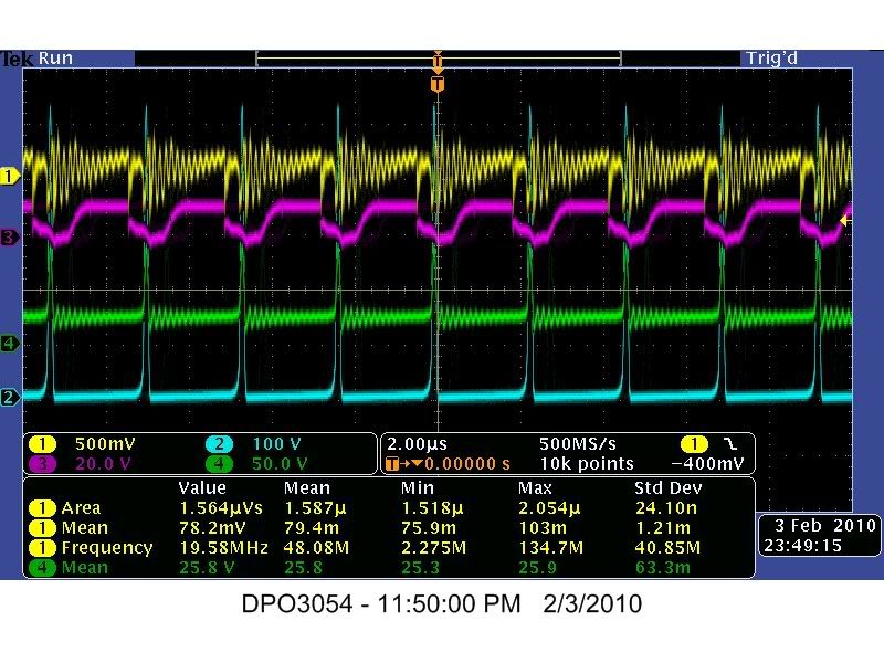
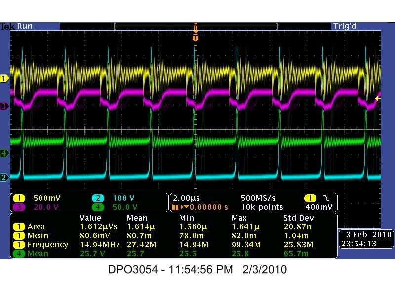
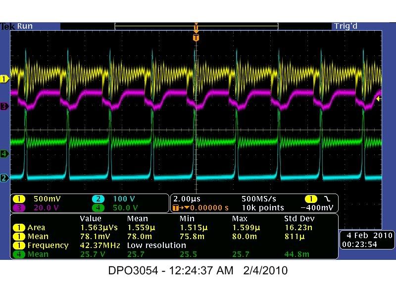
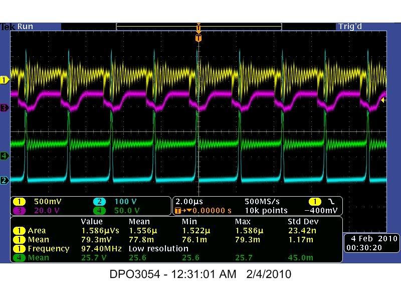
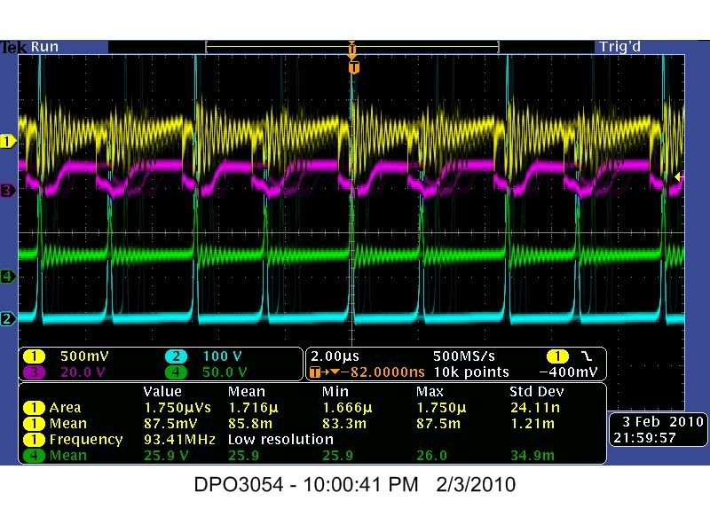
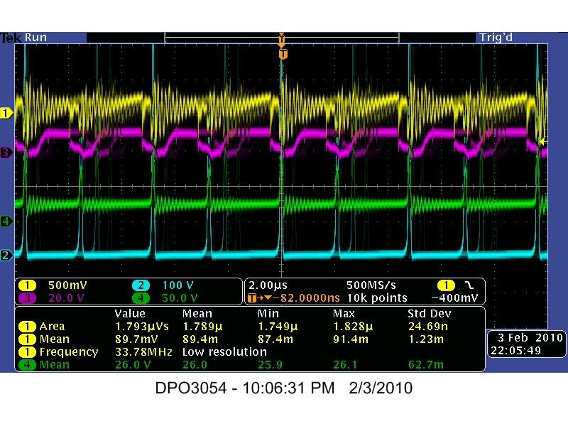
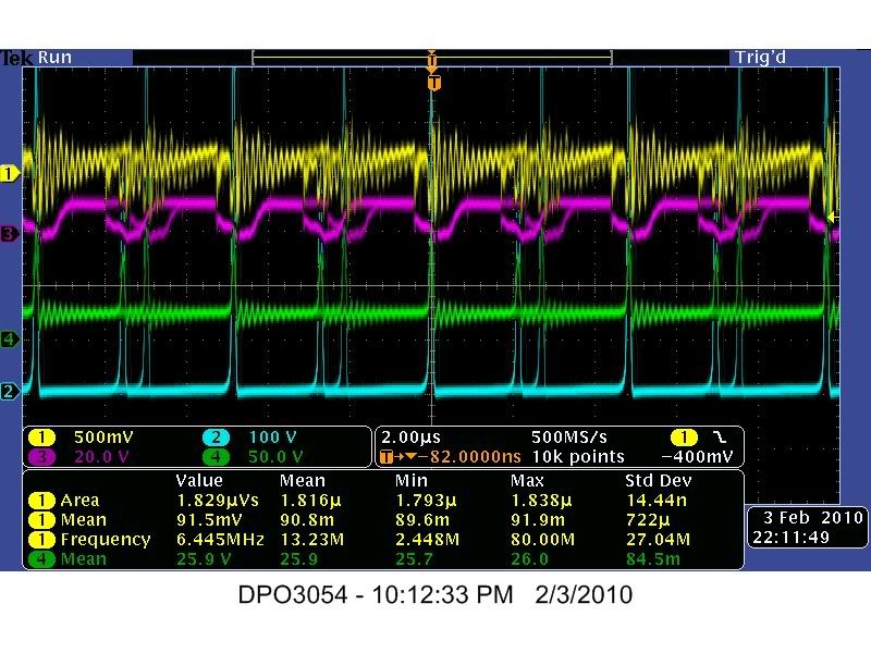
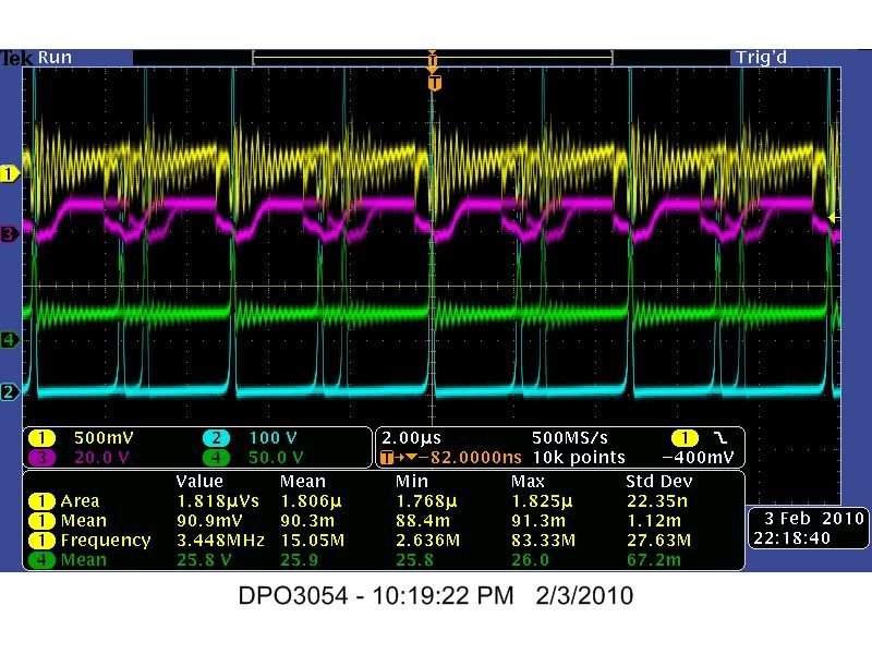
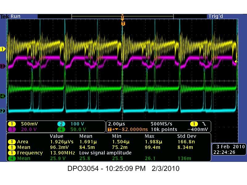
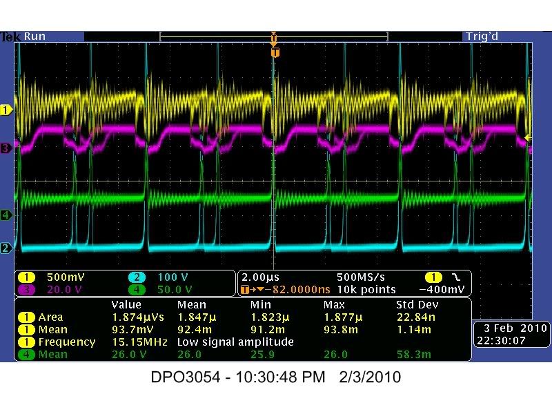
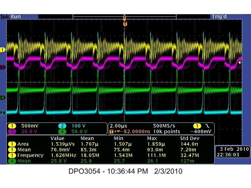
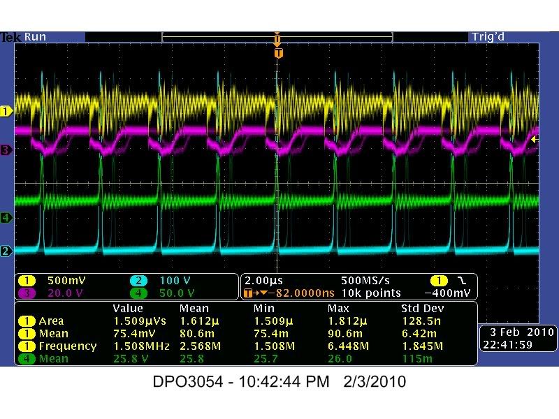
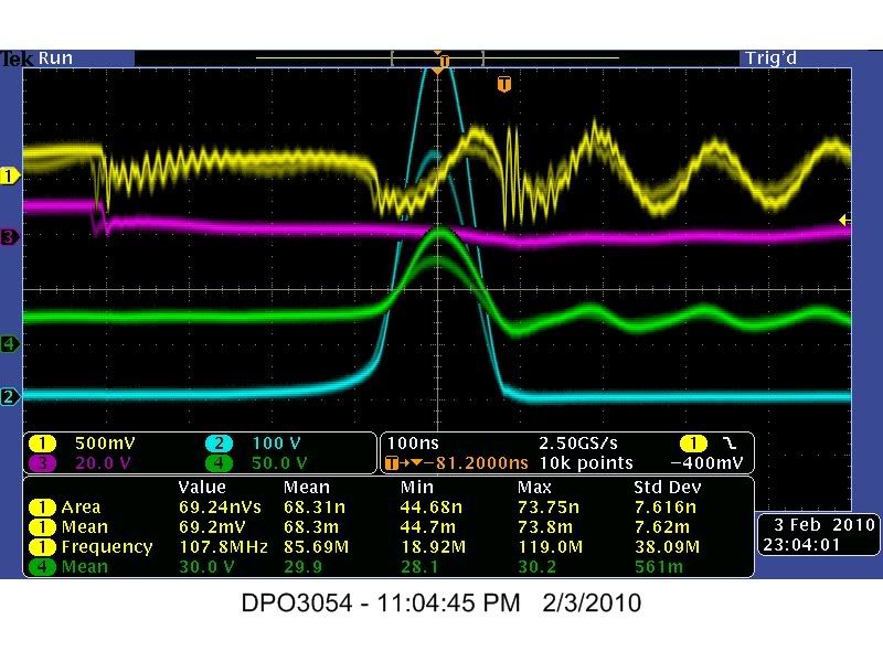
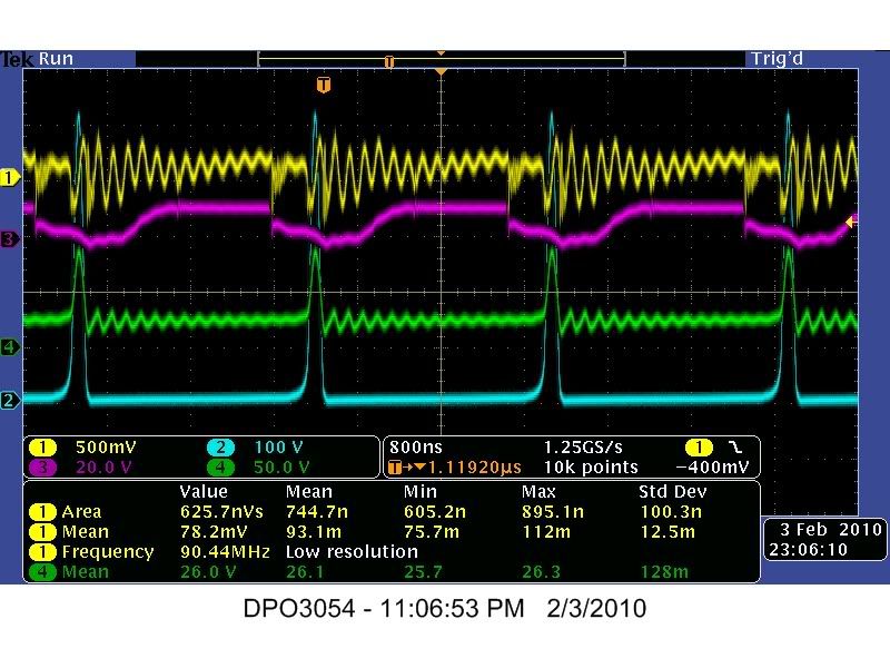
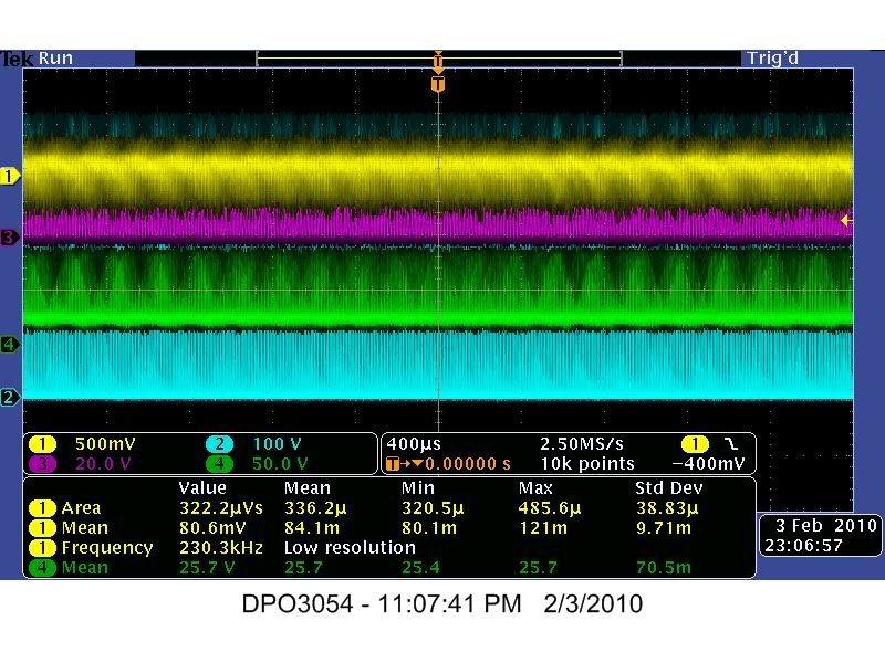
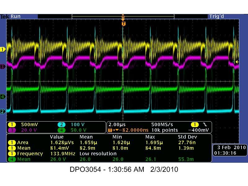
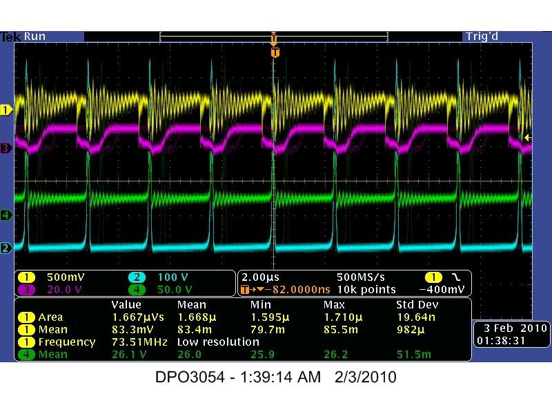
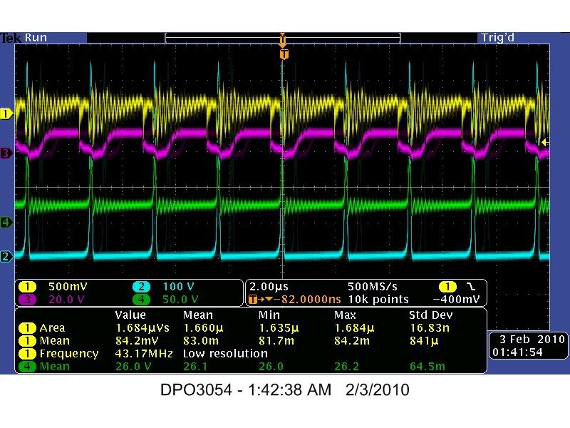
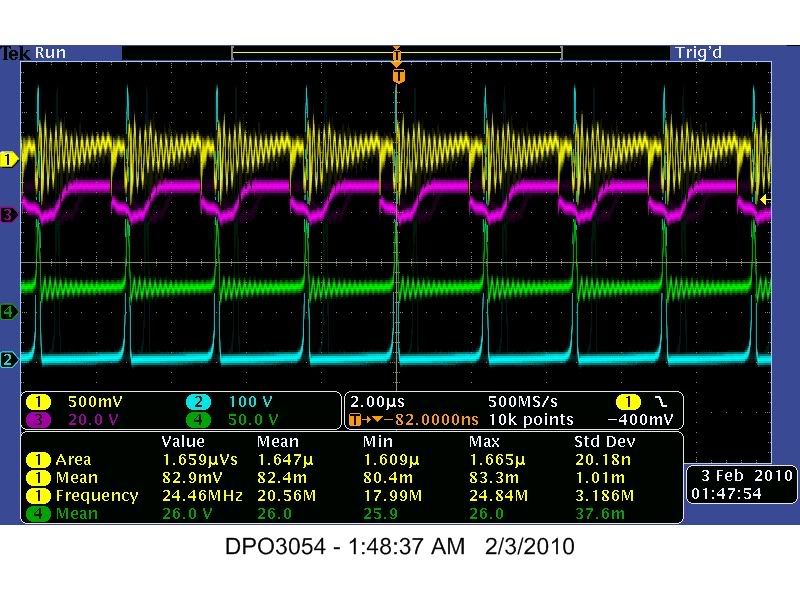
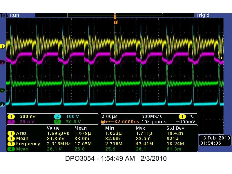
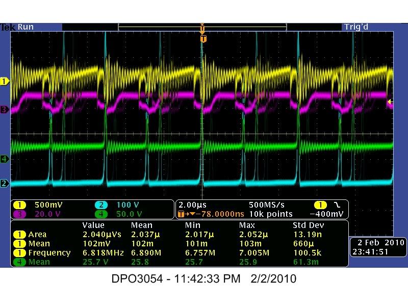
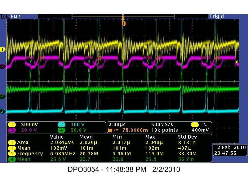
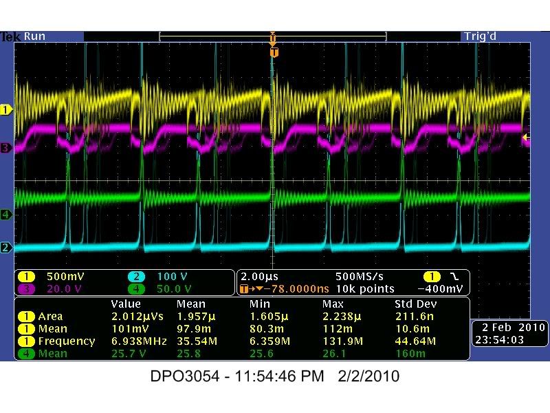
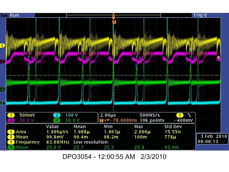
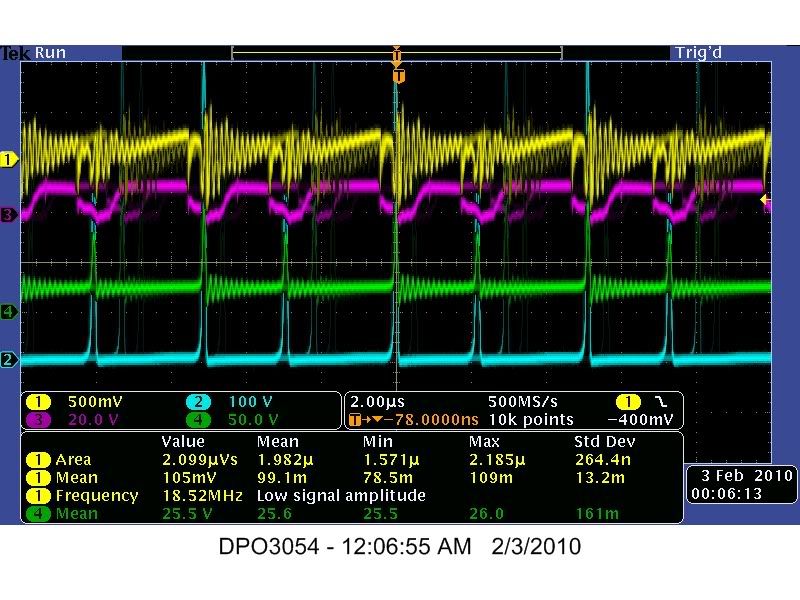
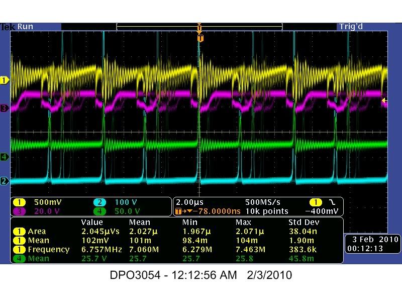
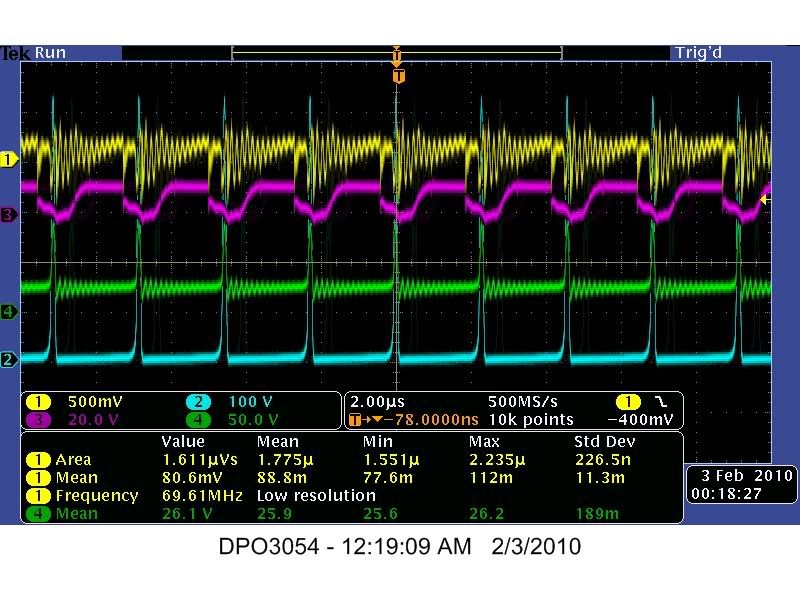
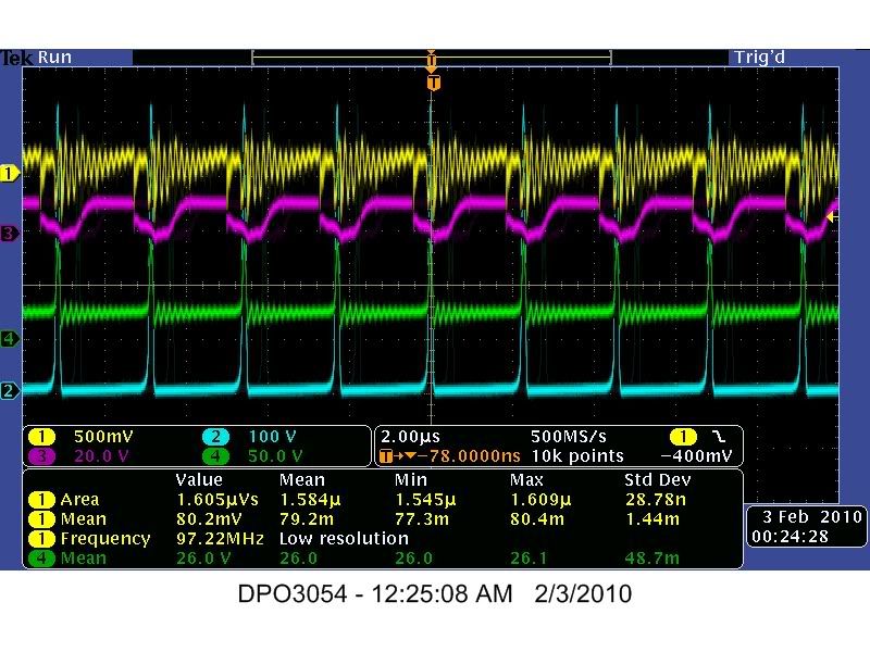
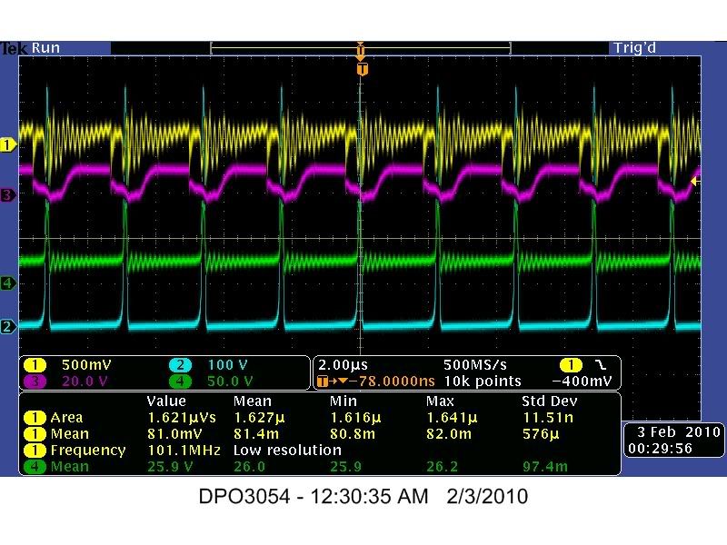
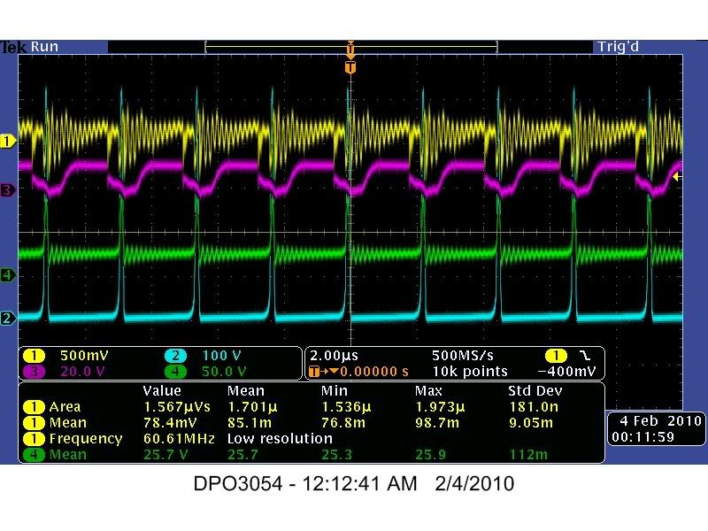
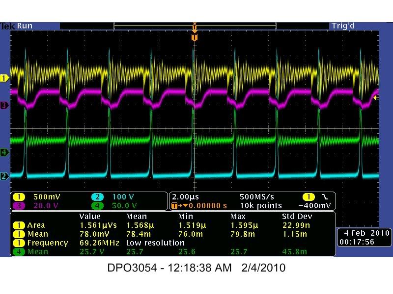
    Here are the Images and Data from TEST #22 these were done with a Tektronix DPO 3054 Oscilloscope using there software called "Open Choice Desktop" with Visa.

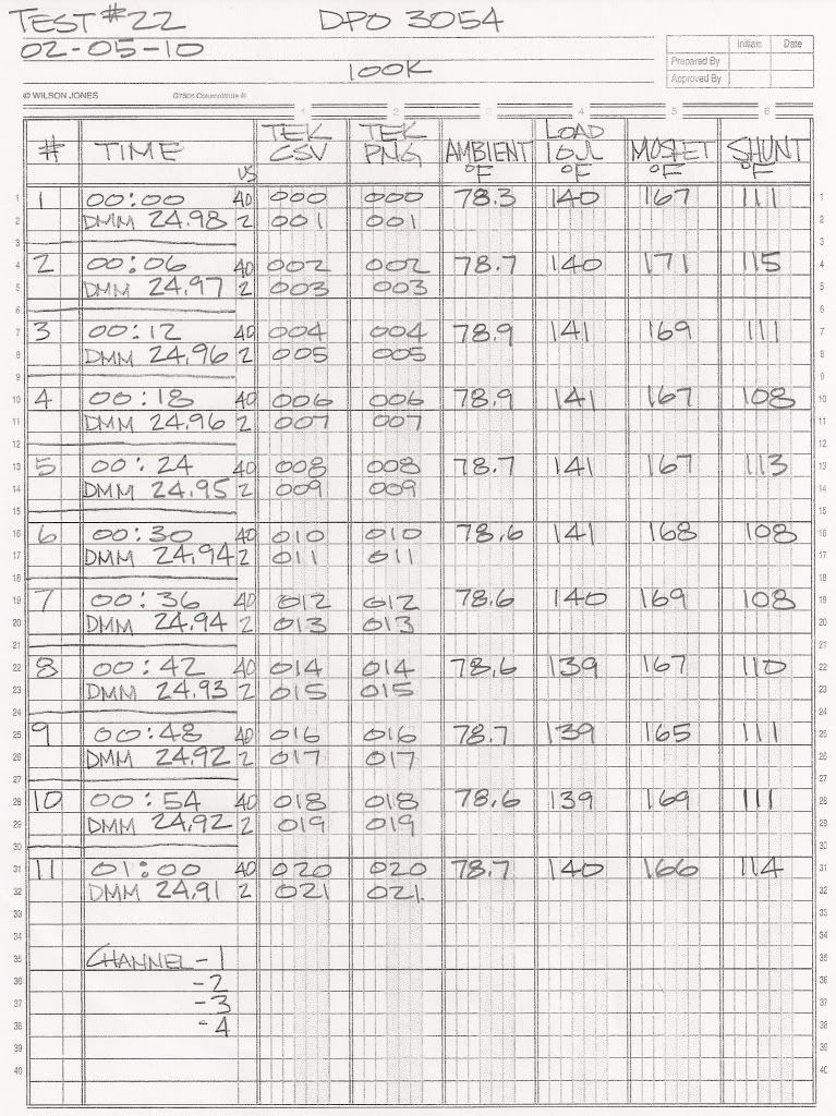
    This is a One (1) Hour test taking Image and Data readings every six (6) minutes using 40us and 2us divisions at 100K


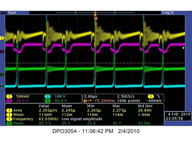
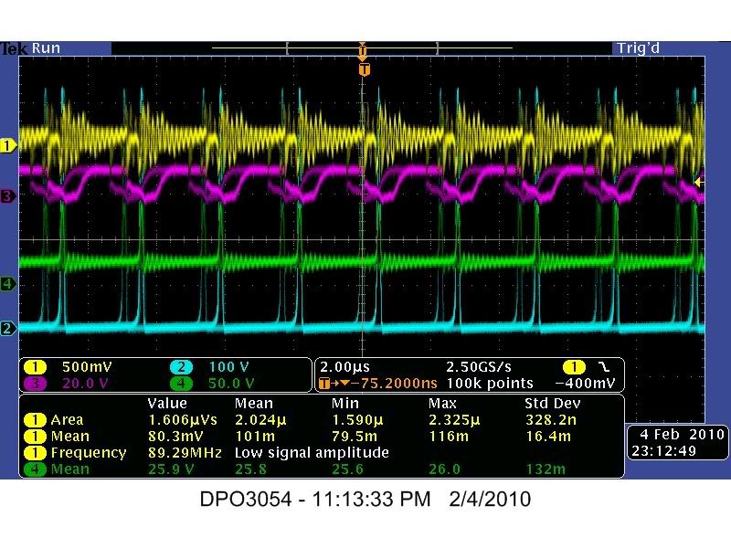
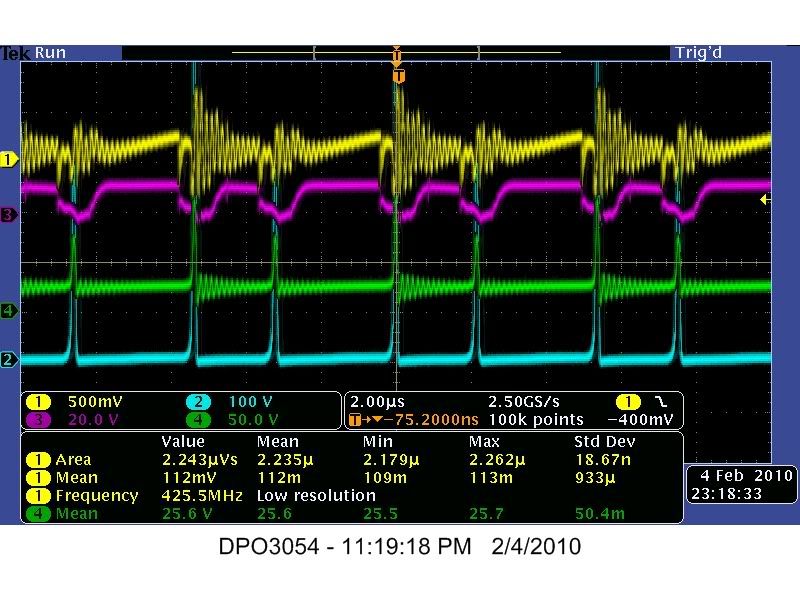
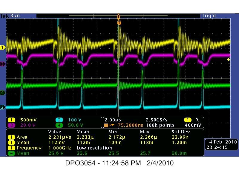
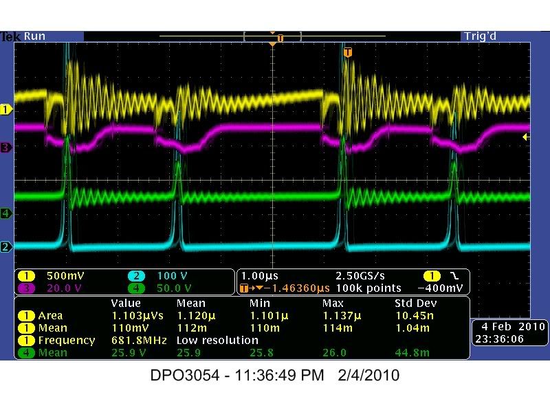
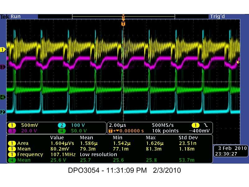
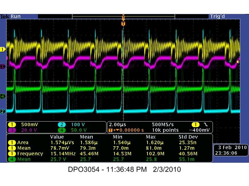
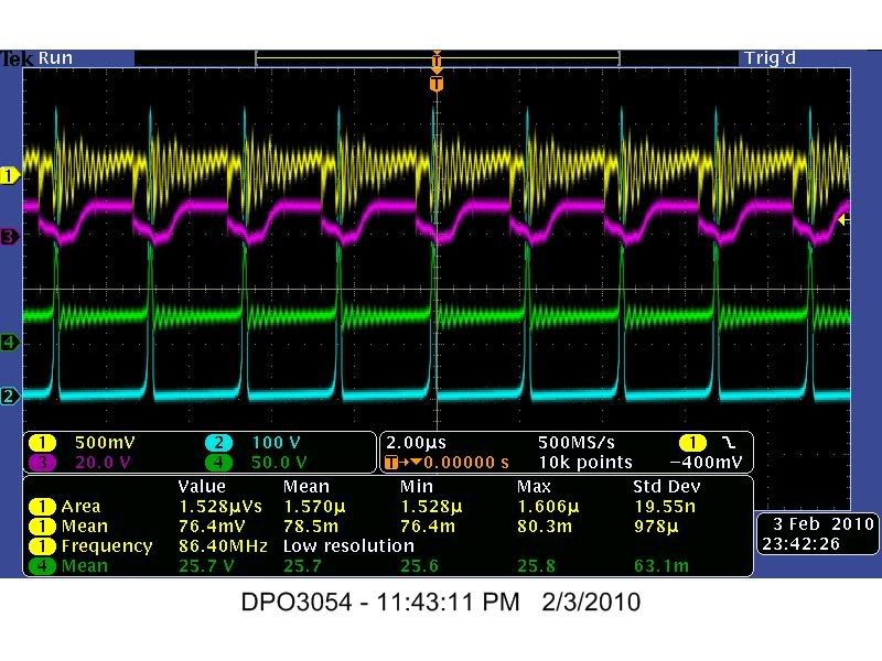
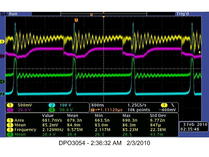
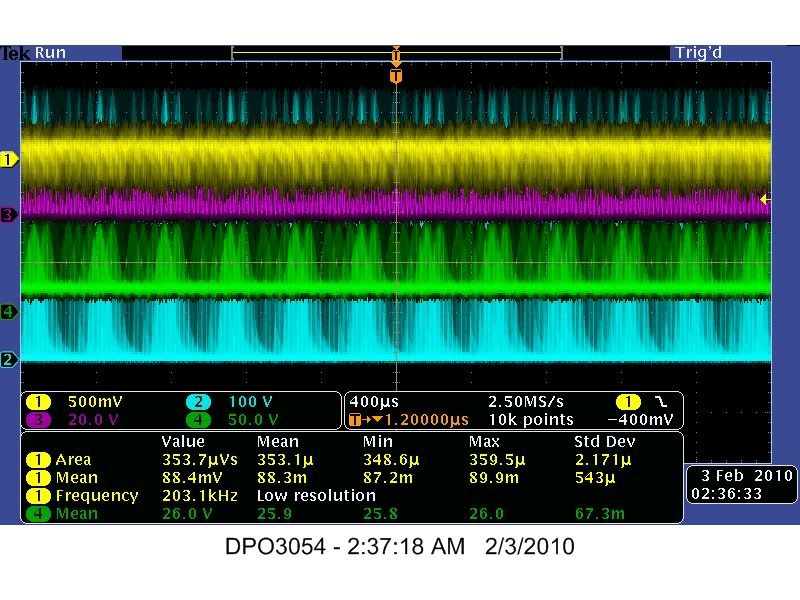
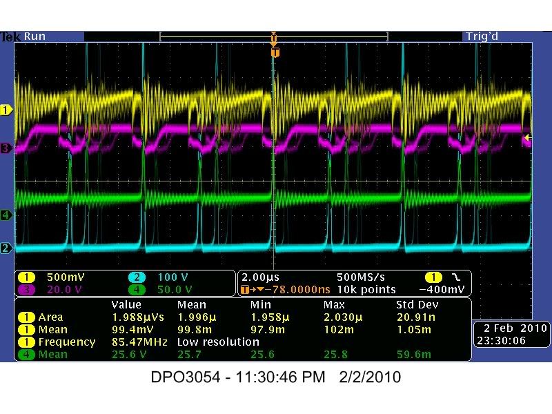
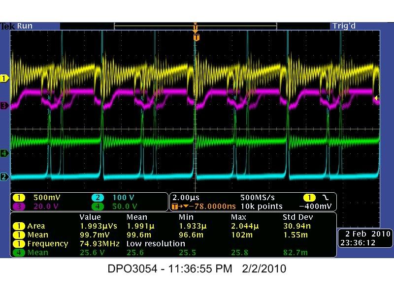
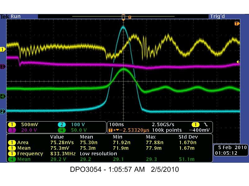
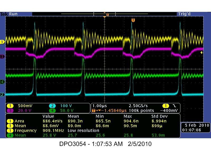
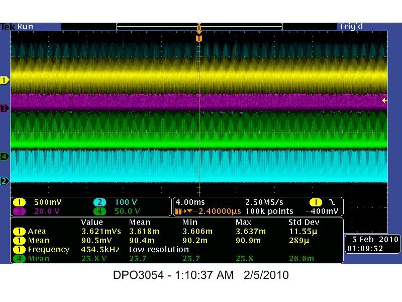
    Channel 1 - Mosfet Source to .25 Ohm Current Sensing Resistor
    Channel 2 - Mosfet Drain Pin to 10 Ohm Load Resistor
    Channel 3 - 555 Timer Pin #3
    Channel 4 - 24 Volt DC Battery Bank


    2us_001
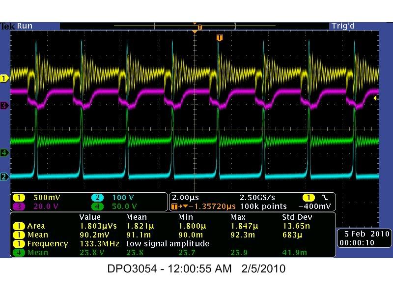

    2us_003
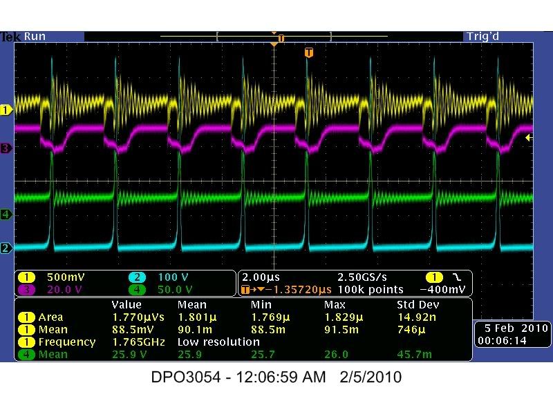

    2us_005
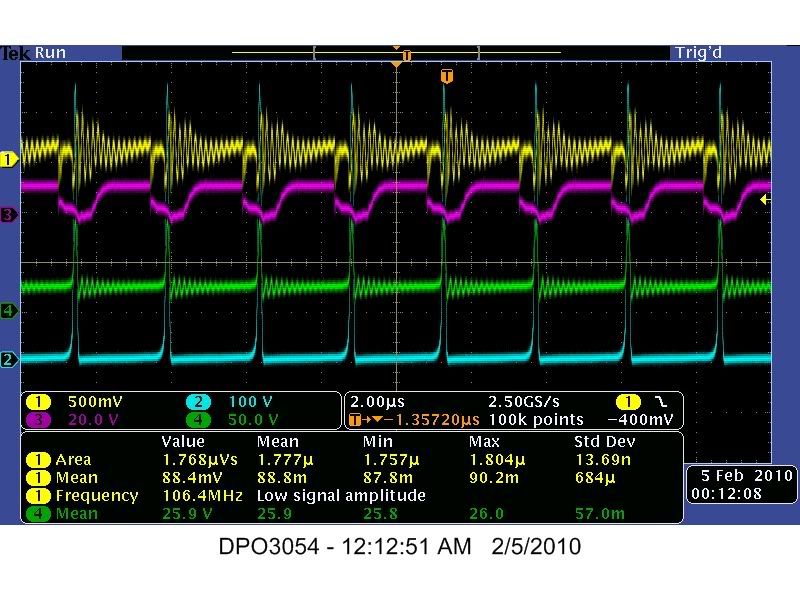

    2us_007
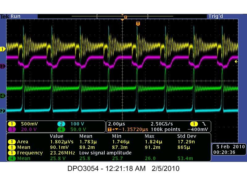

    2us_009
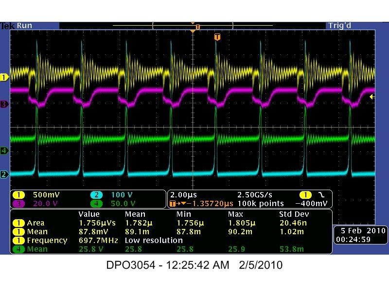

    2us_011
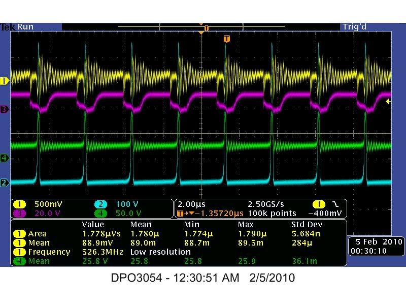

    2us_013
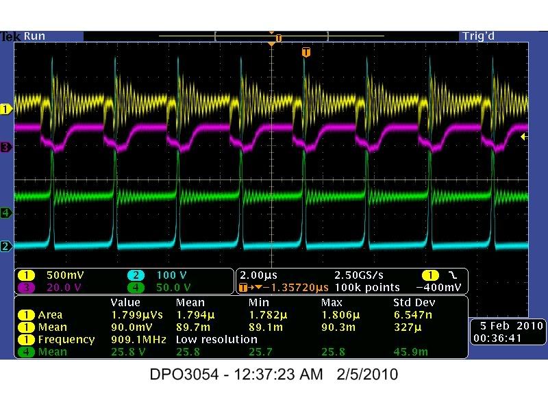

    2us_015
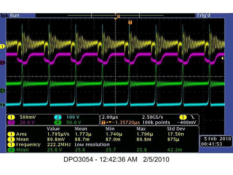

    2us_017
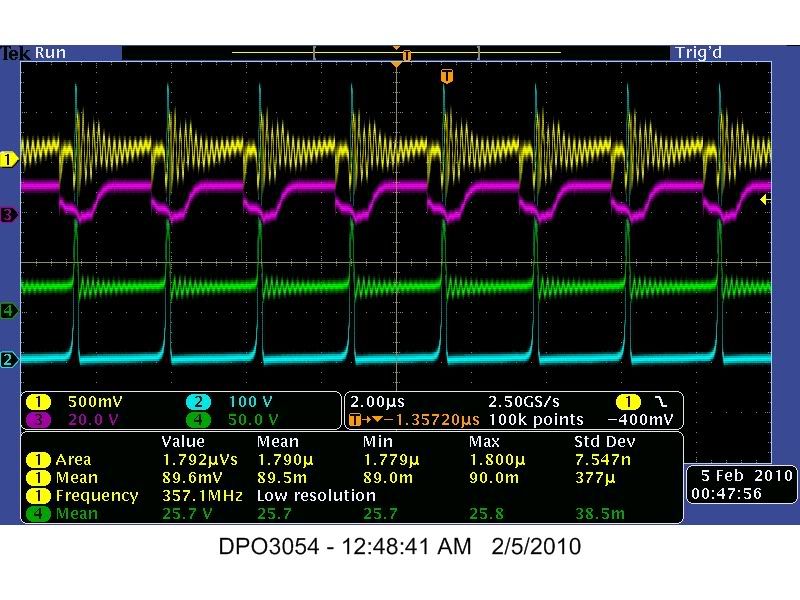

    2us_019
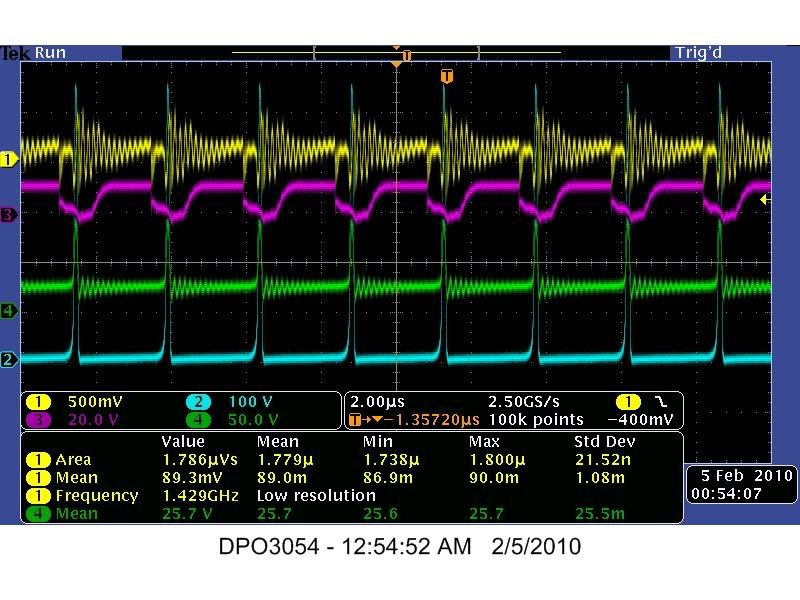

    2us_021
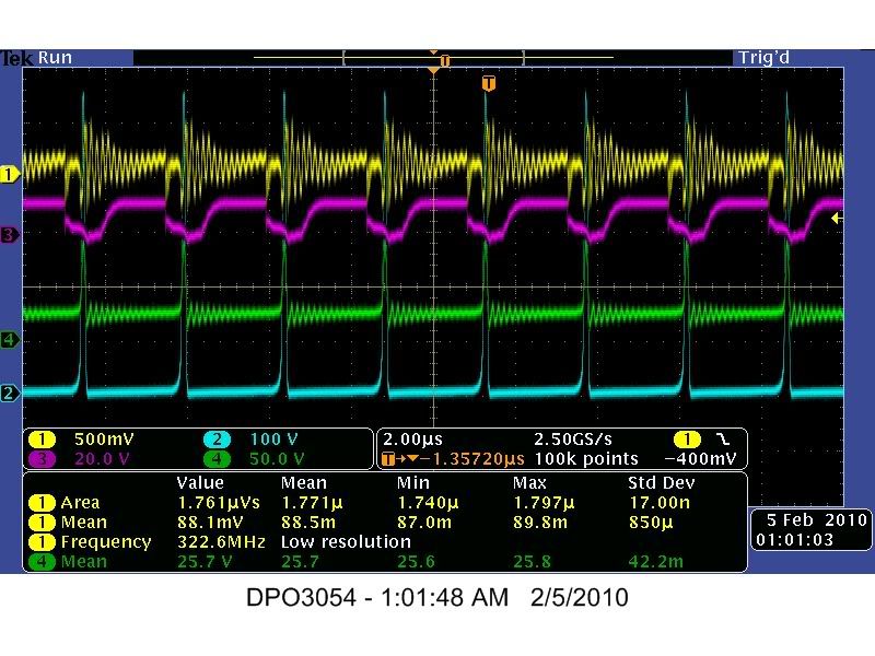


    Image and Data file Key w/ Temperature Readings


    100ns_022

    1us_025

    4ms_030


    Original Test #22 Image and Data files - Zip Format


    Best Regards,
    Glen
    Last edited by FuzzyTomCat; 04-18-2010, 05:42 PM.

    Leave a comment:


  • FuzzyTomCat
    replied
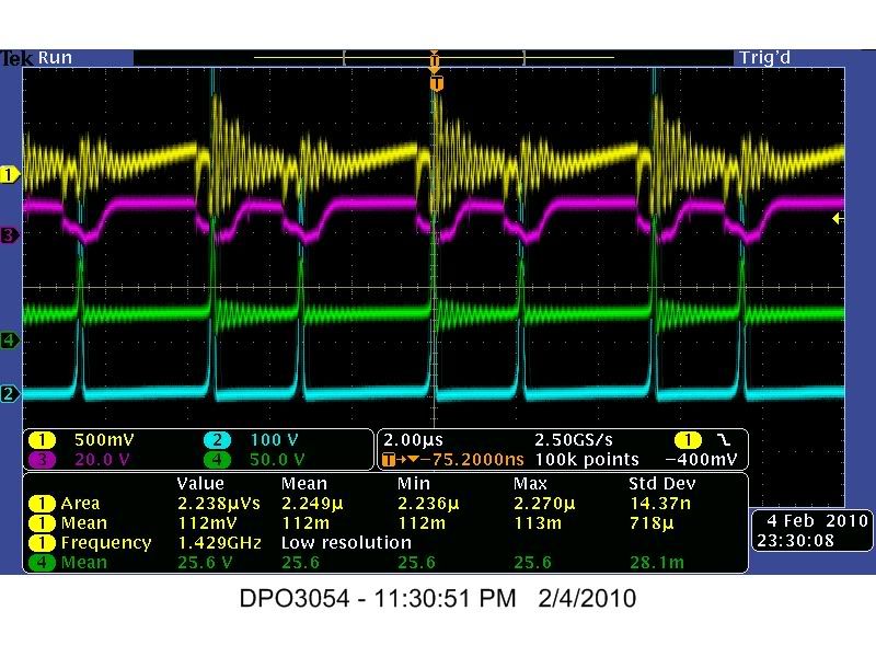
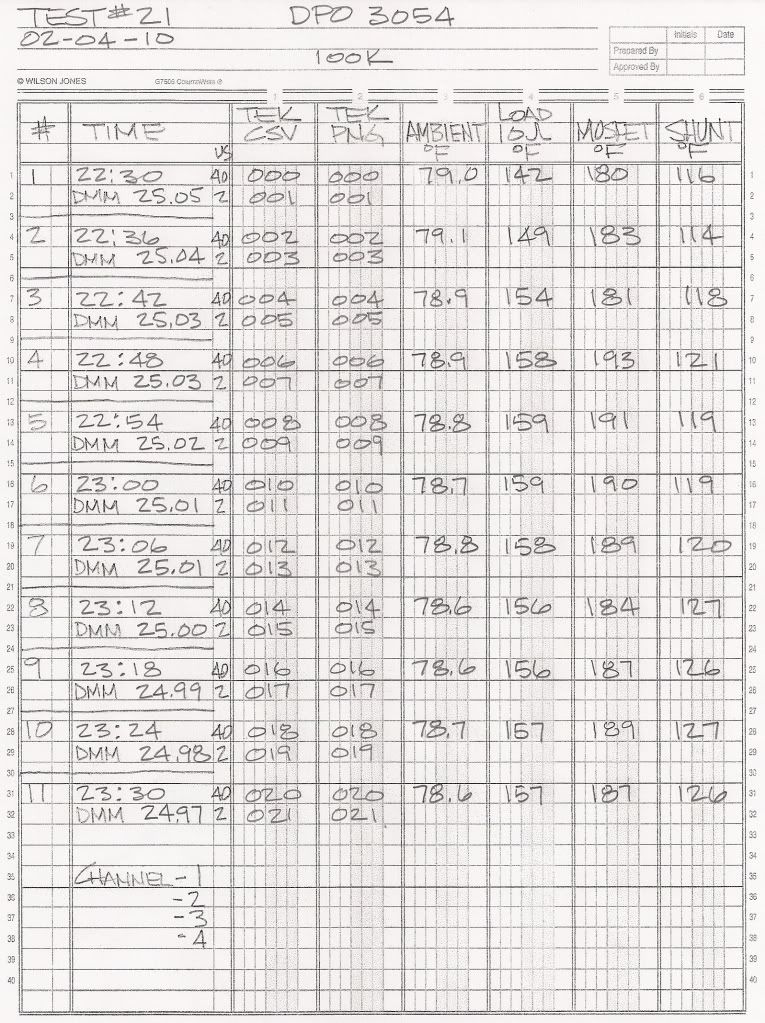
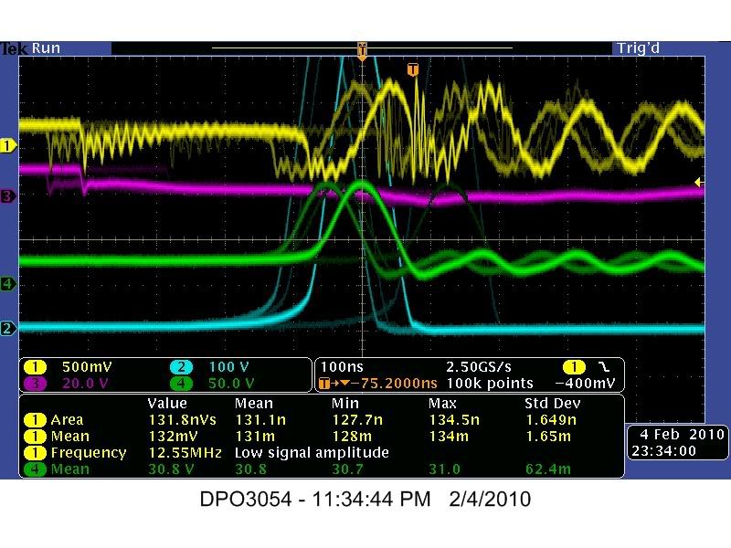
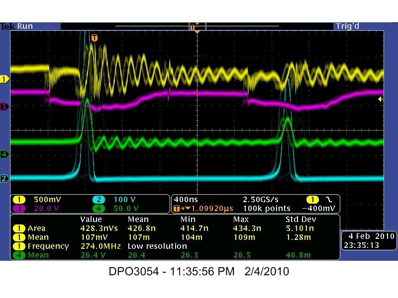
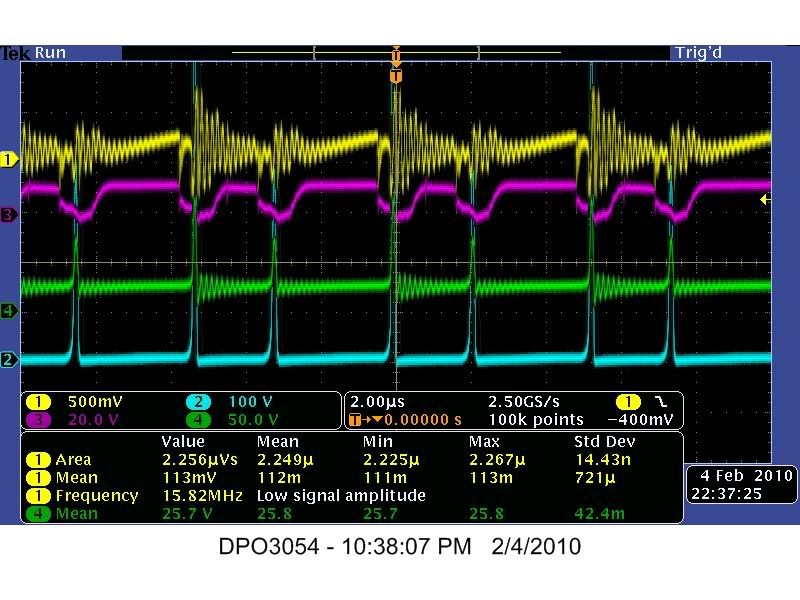
    Test #21

    Hi everyone,

    Here are the Images and Data from TEST #21 these were done with a Tektronix DPO 3054 Oscilloscope using there software called "Open Choice Desktop" with Visa.

    This is a One (1) Hour test taking Image and Data readings every six (6) minutes using 40us and 2us divisions at 100K

    Channel 1 - Mosfet Source to .25 Ohm Current Sensing Resistor
    Channel 2 - Mosfet Drain Pin to 10 Ohm Load Resistor
    Channel 3 - 555 Timer Pin #3
    Channel 4 - 24 Volt DC Battery Bank


    2us_001


    2us_003


    2us_005


    2us_007


    2us_009


    2us_011


    2us_013


    2us_015


    2us_017


    2us_019


    2us_021


    Image and Data file Key w/ Temperature Readings


    100ns_022


    400ns_024


    1us_025


    Original Test #21 Image and Data files - Zip Format


    Best Regards,
    Glen
    Last edited by FuzzyTomCat; 04-18-2010, 05:40 PM.

    Leave a comment:


  • FuzzyTomCat
    replied
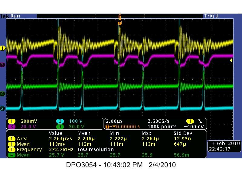
    Test #20

    Hi everyone,

    Here are the Images and Data from TEST #20 these were done with a Tektronix DPO 3054 Oscilloscope using there software called "Open Choice Desktop" with Visa.

    This is a One (1) Hour test taking Image and Data readings every six (6) minutes using 40us and 2us divisions at 10K

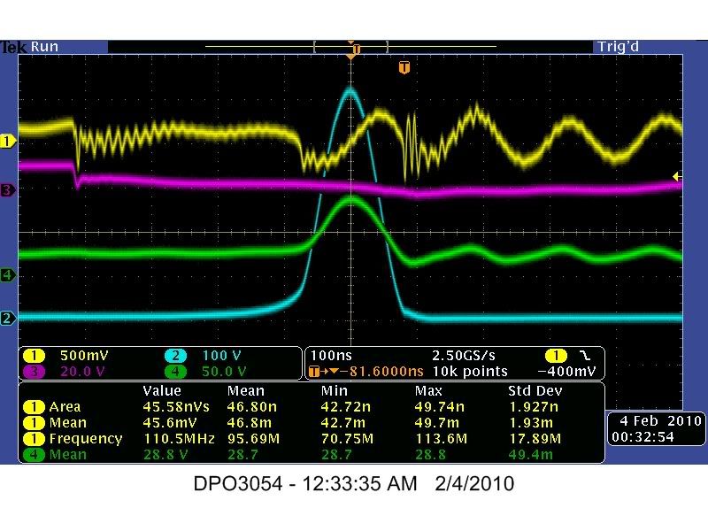
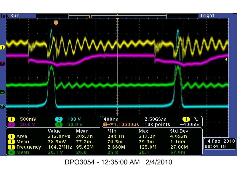
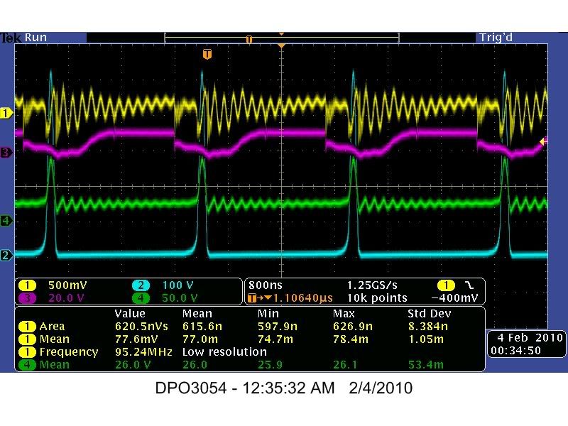
    Channel 1 - Mosfet Source to .25 Ohm Current Sensing Resistor
    Channel 2 - Mosfet Drain Pin to 10 Ohm Load Resistor
    Channel 3 - 555 Timer Pin #3
    Channel 4 - 24 Volt DC Battery Bank


    2us_001


    2us_003


    2us_005


    2us_007


    2us_009


    2us_011


    2us_013


    2us_015


    2us_017


    2us_019


    2us_021


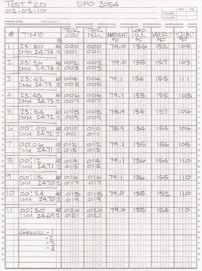
    Image and Data file Key w/ Temperature Readings


    100ns_023


    400ns_025


    800ns_025


    Original Test #20 Image and Data files - Zip Format


    Best Regards,
    Glen
    Last edited by FuzzyTomCat; 04-18-2010, 05:36 PM.

    Leave a comment:


  • FuzzyTomCat
    replied
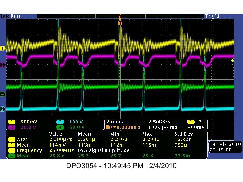
    Test #19

    Hi everyone,

    Here are the Images and Data from TEST #19 these were done with a Tektronix DPO 3054 Oscilloscope using there software called "Open Choice Desktop" with Visa.

    This is a One (1) Hour test taking Image and Data readings every six (6) minutes using 40us and 2us divisions at 10K

    Channel 1 - Mosfet Source to .25 Ohm Current Sensing Resistor
    Channel 2 - Mosfet Drain Pin to 10 Ohm Load Resistor
    Channel 3 - 555 Timer Pin #3
    Channel 4 - 24 Volt DC Battery Bank


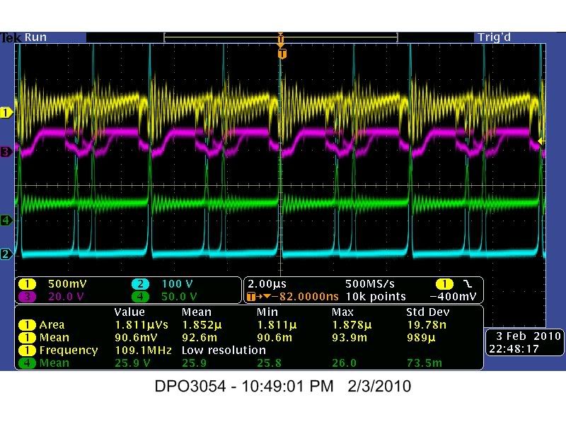
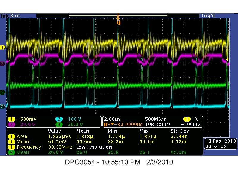
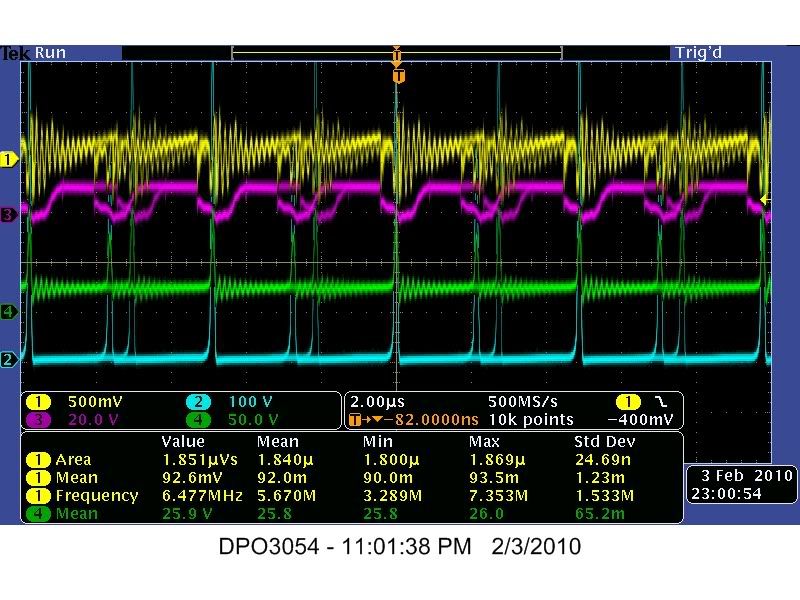
    2us_001


    2us_003


    2us_005


    2us_007


    2us_009


    2us_011


    2us_013


    2us_015


    2us_017


    2us_019


    2us_021


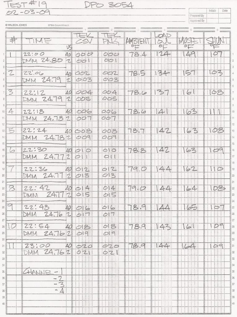
    Image and Data file Key w/ Temperature Readings


    100ns_023


    800ns_025


    400us_026


    Original Test #19 Image and Data files - Zip Format


    Best Regards,
    Glen
    Last edited by FuzzyTomCat; 04-18-2010, 05:35 PM.

    Leave a comment:


  • FuzzyTomCat
    replied
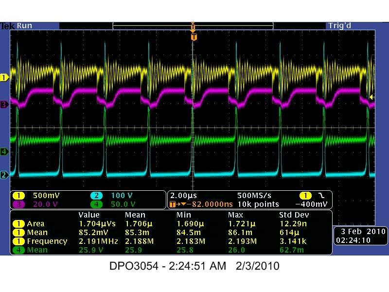
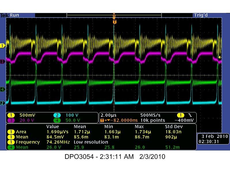
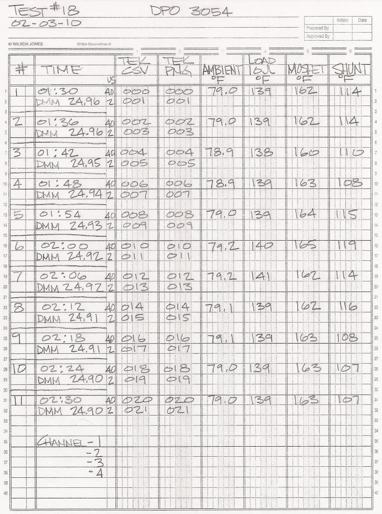
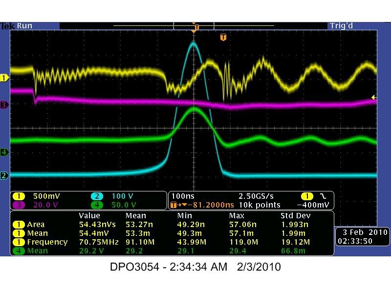
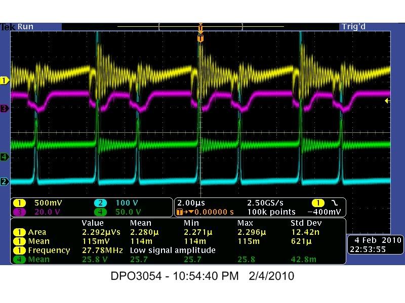
    Test #18

    Hi everyone,

    Here are the Images and Data from TEST #18 these were done with a Tektronix DPO 3054 Oscilloscope using there software called "Open Choice Desktop" with Visa.

    This is a One (1) Hour test taking Image and Data readings every six (6) minutes using 40us and 2us divisions at 10K

    Channel 1 - Mosfet Source to .25 Ohm Current Sensing Resistor
    Channel 2 - Mosfet Drain Pin to 10 Ohm Load Resistor
    Channel 3 - 555 Timer Pin #3
    Channel 4 - 24 Volt DC Battery Bank


    2us_001


    2us_003


    2us_005


    2us_007


    2us_009


    2us_011


    2us_013


    2us_015


    2us_017


    2us_019


    2us_021


    Image and Data file Key w/ Temperature Readings


    100ns_023


    800ns_025


    400us_026


    Original Test #18 Image and Data files - Zip Format


    Best Regards,
    Glen
    Last edited by FuzzyTomCat; 04-18-2010, 05:33 PM.

    Leave a comment:


  • FuzzyTomCat
    replied
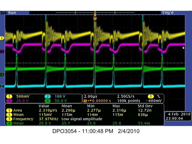
    Test #17

    Hi everyone,

    Here are the Images and Data from TEST #17 these were done with a Tektronix DPO 3054 Oscilloscope using there software called "Open Choice Desktop" with Visa.

    This is a One (1) Hour test taking Image and Data readings every six (6) minutes using 40us and 2us divisions at 10K

    Channel 1 - Mosfet Source to .25 Ohm Current Sensing Resistor
    Channel 2 - Mosfet Drain Pin to 10 Ohm Load Resistor
    Channel 3 - 555 Timer Pin #3
    Channel 4 - 24 Volt DC Battery Bank


    2us_001


    2us_003


    2us_005


    2us_007


    2us_009


    2us_011


    2us_013


    2us_015


    2us_017


    2us_019


    2us_021


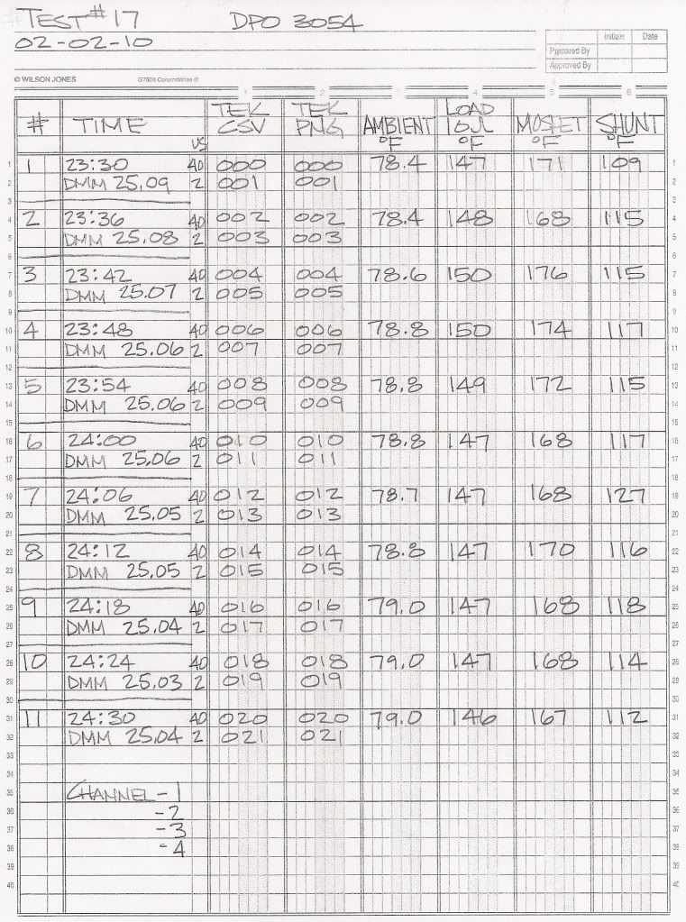
    Image and Data file Key w/ Temperature Readings


    Original Test #17 Image and Data files - Zip Format


    Best Regards,
    Glen
    Last edited by FuzzyTomCat; 04-18-2010, 05:32 PM.

    Leave a comment:


  • FuzzyTomCat
    replied
    Originally posted by Guruji View Post
    Fuzzy which one you found best in efficiency and heating from those heating elements?
    Thanks
    Hi Guruji,

    The one so far using what resistive wire listed is Number 1 for the best circuit efficiency. I will be in the future trying other types of resistive wire Ni Cr "Type B" and possibly some German silver type which I think Aaron is going to try also.

    Best Regards,
    Glen
    Leave a comment:


  • Guruji
    replied
    Heater

    Fuzzy which one you found best in efficiency and heating from those heating elements?
    Thanks

    Leave a comment:


  • FuzzyTomCat
    replied
    Testing Resistor Set

    Hi everyone,

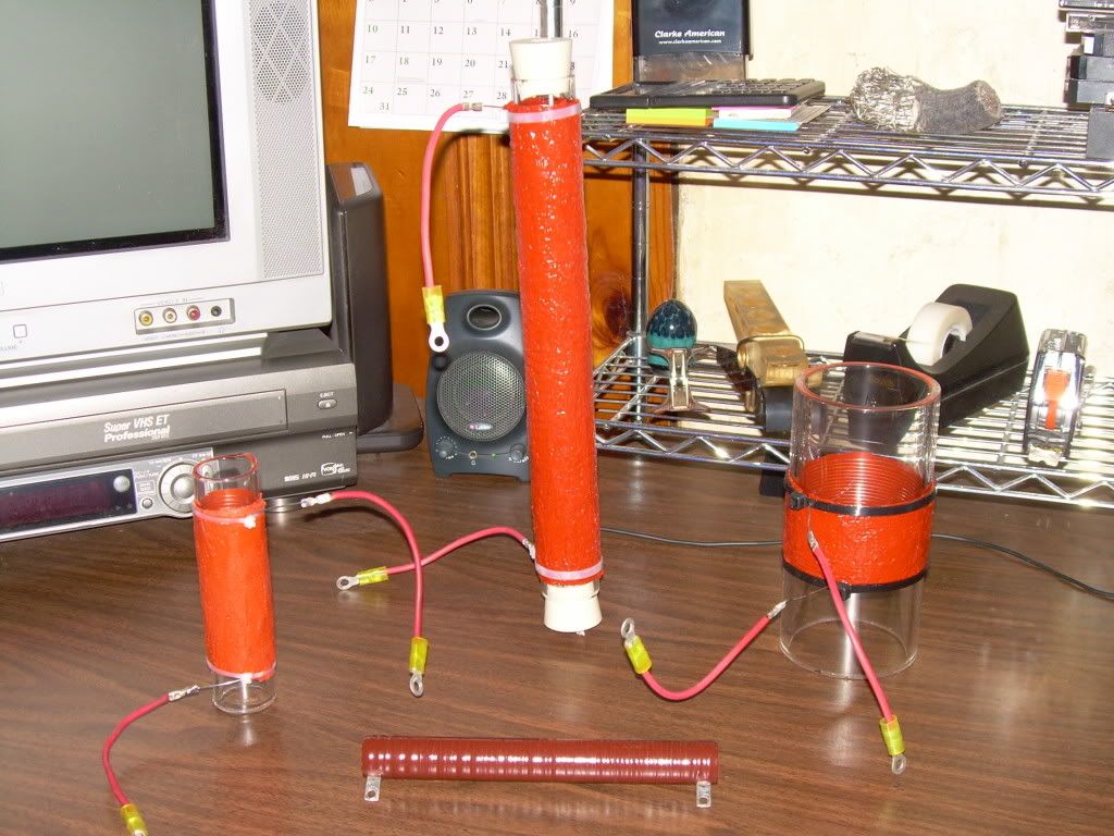
    Here is the set of my prototype 10 Ohm "Borosilicate Glass Tube" ( Pyrex ) wire wound load resistors that has been made for testing and evaluation on the modified replication of the "Mosfet Heating Circuit", resistor specifications are -

    Borosilicate Glass Tube
    "Simax"
    Code Number -246 320 280
    O.D. - 32 mm (#1 and #2)
    I.D. - 26.4 mm
    Wall Thickness - 2.8 mm ( standard medium )
    Length - 6 inches (#1) and 11 inches (#2)
    http://www.pegasus-glass.com/2006_Si..._Catalogue.pdf ( page 6 )

    Resistance Wire
    AWG 20 [.032 dia] "Ni Cr" Type A - 80% nickel, 20% chromium (.6348 ohms ft.)
    Spacing - 1mm (+ -)
    Turns - 43 to 48 (maintain 10 Ohms, + - 5% maximum)

    RTV Silicone
    "Permatex"
    Red High Temp RTV Silicone
    Continuous Operating Temperatures °F -65 to 600 (°C -54 to 316)
    Red High Temp RTV Silicone #81409


    Picture from Left to Right

    1) 32 mm diameter , coil length 3.375 inches , wire spacing gap 1 mm , uH - 20.41 ( calculated )
    Complete Construction Details

    2) 32 mm diameter , coil length 10 inches , wire spacing gap 4.762 mm ( approx ) , uH - 8.64 ( calculated )

    3) 76 mm diameter , coil length 1.750 inches , wire spacing gap 1 mm , uH - xxx ( calculated )

    Picture Center Front

    4) 19 mm diameter , coil length 6.5 inches , uH - 18.81 ( calculated )
    100 watt , Memcor # FR100 / 7931 "Off The Shelf Store Bought"


    I hope this information is helpful in any replications experimenters may have.

    Best Regards,
    Glen
    Last edited by FuzzyTomCat; 10-26-2010, 03:57 AM. Reason: added information

    Leave a comment:


  • FuzzyTomCat
    replied
    Test #1 through Test #16

    Hi everyone,

    Here is a listing of all my previous Tests #1 through #16 on the modified replication of the "Mosfet Heater Circuit" Energetic Forum links, with additional complete Tektronix Oscilloscope "Image and Data" files for each one.

    TEST #1
    Test #1
    TDS 3054C Data and Image files - TEST #1

    TEST #2
    TEST #2
    TDS 3054C Data and Image files - TEST #2

    TEST #3
    TEST #3
    TDS 3054C Data and Image files - TEST #3

    TEST #4
    TEST #4
    TDS 3054C Data and Image files - TEST #4

    TEST #5
    TEST #5
    TDS 3054C Data and Image files - TEST #5

    TEST #6
    TEST #6
    TDS 3054C Data and Image files - TEST #6

    TEST #7
    TEST #7
    TDS 3054C Data and Image files - TEST #7

    TEST #8
    TEST #8
    TDS 3054C Data and Image files - TEST #8

    TEST #9
    TEST #9
    TDS 3054C Data and Image files - TEST #9

    TEST #10
    TEST #10
    TDS 3054C Data and Image files - TEST #10

    TEST #11
    TEST #11
    TDS 3054C Data and Image files - TEST #11

    TEST #12
    TEST #12
    TDS 3054C Data and Image files - TEST #12

    TEST #13
    TEST #13
    TDS 3054C Data and Image files - TEST #13

    TEST #14
    TEST #14
    TDS 3054C Data and Image files - TEST #14

    TEST #15
    TEST #15
    TDS 3054C Data and Image files - TEST #15

    TEST #16
    TEST #16
    TDS 3054C Data and Image files - TEST #16


    If any other information is needed on the previous tests that I may have or not listed please don't hesitate to ask ...

    Best Regard's,
    Glen
    Last edited by FuzzyTomCat; 10-26-2010, 03:56 AM. Reason: correct link

    Leave a comment:


  • Harvey
    replied
    Hi All - and to the new thread

    In this post I would like to address the concerns that most engineers and academics have regarding the mixture of energy from different power sources and the difficulty of keeping these separate during the data acquisition and recording. I have provided 3 different modifications to Glen's arrangement that provide a means of removing the secondary energy source from the circuit and will list the pros and cons of each modification.

    First we have Mod A:
    Here we have the simple addition of a readily available 7812 voltage regulator to allow the timer circuit to be powered by the 24V Supply directly. However, this modification requires a blocking diode to prevent the >90V inductive BEMF from damaging the regulator which is rated at 35V Max input.

    Click This Link For Larger Image

    MOD A Pros:
    1. The CSR values represent 100% of the current flowing back to the battery including all Timer related current. Mesh Currents become a non-issue.
    2. A more accurate battery power value is recorded as the BEMF is prevented from inflating this measurement
    3. Scope probe positioning is retained from previous tests allowing similar adjustment protocols as previously used.
    4. COP registrations will increase as all inductive energy is trapped between the blocking diode and the HEXFET forcing the energy to be dissipated in the Load (R3). [this feature requires sufficient time between retriggering to allow full transformation of the energy to heat]
    5. Regulator only requires a 2.6V overhead - will work with total battery voltage as low as 14.6V - Good for endurance runs
    6. No additional components needed to set regulator voltage.
    7. Very large BEMF values on the blocking diode cathode can be withstood, up to 1000V

    MOD A Cons:
    1. The Batteries will not be recharged. The blocking diode forces that energy back to the Load (R3) to be dissipated.
    2. Obtaining the Preferred Mode Of Oscillation will be more difficult because the voltmeter reference will always show a discharge commensurate to the actual total energy consumption.
    3. The Linear regulator adds to the total energy consumption
    4. Addition of the regulator requires involved modifications to the existing circuit

    MOD A Conclusion:
    Use this configuration for high COP accurate energy consumption tests.

    ==================================================

    MOD B:

    The Mod B configuration is very similar to Mod A, but uses a High Voltage TL783 Regulator that does not require the blocking diode. However, this regulator does require the addition of resistors to set the output voltage to the desired level.

    Click This Link For Larger Image

    MOD B Pros:
    1. The CSR values represent 100% of the current flowing back to the battery including all Timer related current. Mesh Currents become a non-issue.
    2. Scope probe positioning is retained from previous tests allowing similar adjustment protocols as previously used.
    3. Source Battery is allowed to recharge
    4. Obtaining the Preferred Mode Of Oscillation will be essentially unchanged from previous tests
    5. Meter connections are retained with the same function as previous tests

    MOD B Cons:
    1. BEMF is allowed to inflate Voltage Source measurements giving a false indication of actual battery consumption.
    2. BEMF energy at the battery is limited to 125V max
    3. The Linear regulator adds to the total energy consumption
    4. Extra resistors are needed to set the output voltage of the Regulator
    5. COP values will be less than optimum as some of the BEMF energy is used to recharge the battery rather than heat the Load (R3).
    6. The regulator has a high dropout voltage of over 21 volts - this limits endurance runs where recharging is unable to exceed or stall consumption.
    7. Addition of the regulator requires involved modifications to the existing circuit

    MOD B Conclusion:
    Use this Mod where battery recharging is desirable along with retaining former equipment configurations.

    ================================================== =


    MOD C:
    This is really the most simplistic modification with regards to circuit changes. However, it necessitates a radical departure of the equipment connections and data acquisition. This is due to the fact that we are using a tapped supply source with two different voltage levels. Each must be properly monitored to accurately calculate the battery delivery power. This requires all four scope probes to be dedicated to obtaining the information required to calculate the total power delivered. Mesh currents are inherently addressed in either of the two branches for any instant in time.


    Click This Link For Larger Image

    MOD C Pros:
    1. Very Simple modification, no new parts are required as the secondary CSR is already in place from a previous Mesh Current test.
    2. Separate data collection for the timer circuit consumption and the Load circuit consumption.
    3. No Regulator to add to the energy consumption
    4. Battery Recharge is enabled
    5. Meter connections are retained with the same function as previous tests.
    6. There is no component limit to the BEMF other than HEXFET avalanche and battery plate arcing (which would be very bad - even explosive - maybe this should be a Con?).

    MOD C Cons:
    1. Major changes in Scope Probe connections and function. We lose the Gate reference and the Drain Pulse reference in our data acquisition.
    2. Due to Con#1, obtaining the Preferred Mode Of Oscillation will be very problematic - a separate scope may be necessary to facilitate this function.
    3. COP values will be less than optimum as energy is used to recharge the batteries.


    MOD C Conclusion:
    Use this mod where minimum circuit consumption is desired and a separate record of each branch is needed. A pre-calibrated circuit may be necessary prior to data acquisition. This arrangement would be good for very long endurance runs.


    Cheers,

    Leave a comment:


  • FuzzyTomCat
    replied
    Originally posted by Guruji View Post
    Hi Fuzzy Aaron comes here? Cause I want to talk to him about his circuit of the one 12v battery that it's working.
    Thanks
    Yes, he will and he is very much part of the group, glad to see you made it !

    Best Regard's,
    Glen

    Leave a comment:


  • Guruji
    replied
    Heating circuit

    Hi Fuzzy Aaron comes here? Cause I want to talk to him about his circuit of the one 12v battery that it's working.
    Thanks

    Leave a comment:


  • FuzzyTomCat
    replied
    Mosfet Heating Circuit - Videos

    Hi everyone,

    I would like to also reference that at the "Open Source Research and Development" Channel there is a latest video library of available "LIVE" 5 Hour non stop recordings of various Oscilloscope wave forms, temperature readings and device shots of the modified Mosfet Heating Circuit available for your viewing pleasure.

    Tektronix TDS 3054C
    7 - Recordings or 33 Hours

    Tektronix 2445A
    1 - Recording of 5 Hours

    Tektronix DPO 3054
    1 - Recording of 5 Hours

    *Highlights* on January 9, 2010, January 24, 2010 and January 31, 2010 with the preferred mode of operation shown.

    Best Regards,
    Glen
    Leave a comment:


  • FuzzyTomCat
    started a topic Mosfet Heating Circuits

    Mosfet Heating Circuits

    Hi everyone,

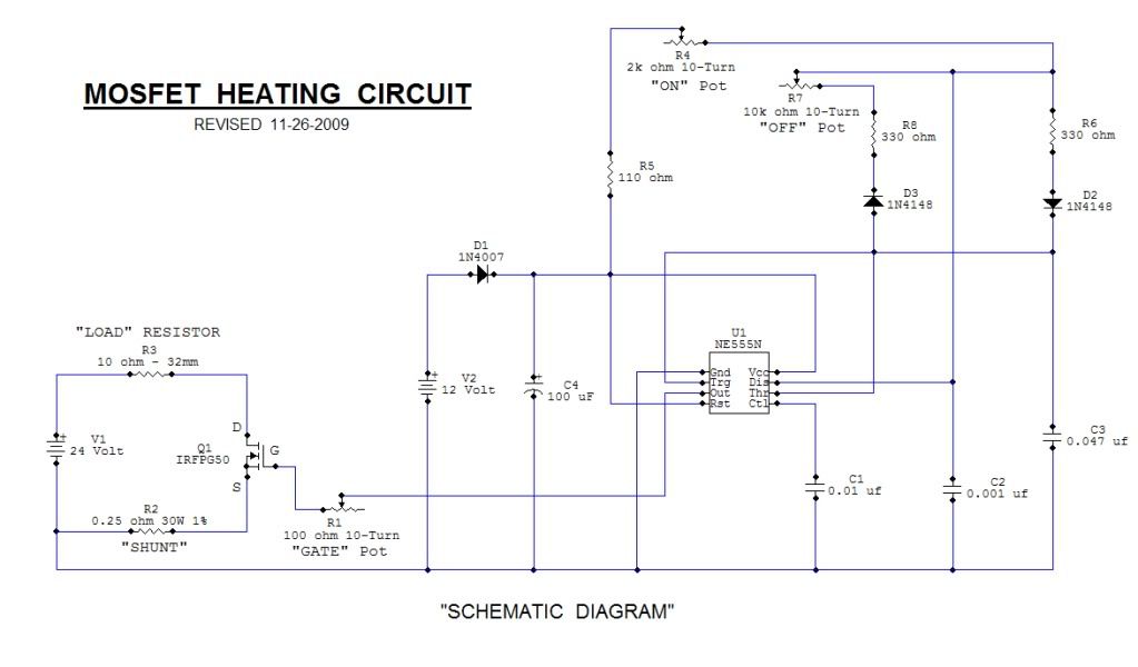
    This Open Source thread is for the advancement of a "Mosfet Heating Circuit" one that is a modified replication of one described in the Quantum October 2002 article.


    The goal is to provide all possible updates and modifications to the existing "Revised 11-26-2009" circuit to find a higher "Coefficient of Performance" or COP using the latest circuit components, technology and equipment available for the advancement of this present circuit being used.

    It will also given the time needed to document and fully evaluate previous testing and future testing on a submittal for possible publication in a accredited Journal or Magazine and Scribd the worlds largest on line publisher.

    Please .... refrain from cutting and pasting this threads context to other "Energetic Forum" threads with questions or comments.

    Best Regards,
    Glen
    Last edited by FuzzyTomCat; 10-13-2010, 09:19 PM. Reason: Up-Dated
Working...
X