-
-
I have a question
Hi all,
I have a question, how can we measure the wattage going into the resistor when it is across two phases, one reading 69.1v and the other 78.5v when measured independantly, the voltage across the two phases is 133v. we are talkig AC here.
I did take a reading on DC as well:- 7.74 and 11.06 both positive so it has to be AC
Maybe Harvey can answer this one!
Maybe the electrons are hitting each other in the middle of the resistor and creating heat or maybe this is nothing to laugh about!
MikeComment
-
Red Alert
Hi Guys. Just to alert everyone to a really clever ploy in hacking that has now become evident.
Glen supposedly sent the following message to Harvey
'Hey Harvey, I got some new wave forms Rosie wanted me to send you and maybe some .XLR spread sheet info ... not posted yet ...Aaron is now also trying to replicate the new finding' - Glen L...
The point being that Fuzzy never sent this. And who knows what was in that file.
Harvey also found himself in a typed dialogue conversation with someone who was - again - not Glen and Glen then became the confused recipient of Harvey's replies.
Strange things afoot. Just double check the sender before you open files on Skye. And it's possible that voice identification is possibly the safest. Golly. So much intrigue about this little circuit.
Comment
-
Comment
-
This should put the question about returning energy to bed.Originally posted by FuzzyTomCat View PostComment
-
The Single Conduit Multi Vortex
Nikola Tesla once said that whatever electricity is, it acts like an incompressible fluid. Note the distinction here between fluid and liquid, they are not the same things. James Clerk Maxwell envisaged magnetic vortices swirling around Faraday's 'lines of force' which led to his famous 8 equations of which 4 are in particular use in classical physics involved with electromagnetic radiation today. Viktor Schauberger applied the vortex phenomenon to actual fluid dynamics involving real liquids and demonstrated how the shear zone between two vortices can have nearly zero resistance, and the shear zone between a single vortex and the conduit in which it travels can reduce the restriction of the forward movement of the fluid by reducing or preventing cohesive action.
When voltage and/or frequency increase, the current produced in a conductor tends to move from the inward material area to the outward surface area. This effect is referred to as the Skin Effect and you can discover the principle behind it by clicking on the link embedded in the forgoing term.
Today, I would like to entertain the possibility that a vortex current structure could form in specific resonant circuits that exhibit a dual function with regards to the voltage and/or frequency of the circuit. In this case, we may have a low voltage, low frequency, high current condition flowing in one direction in the conductor center, while we may have a high voltage, high frequency, low current condition flowing on the same conductor surface in the other direction - simultaneously.
Ok...most of you are doing this right now.... wait for it...and now
  , you ask, "is it even possible?"
Yes We know for a certainty that we can move fluids in two different directions simultaneously in the same conduit. We also know conclusively, that this action results in a transfer of energy from the one vortex to the other in order to conserve its angular momentum. Could Tesla be correct? Could electricity behave in the exact same way? Tesla also stated that electric current behaved as if it contained momentum, especially in inductive circuits. This would be necessary if an exchange were to occur between two coaxial vortices in the same conductor. The most remarkable aspect of this scenario is the possible internal action of a transformer in a single straight wire.
Our measurement equipment is most often attached to the surface of our conductors. Therefore, we may not be getting the whole picture. Instead, we may only be seeing what is happening on the surface and missing what is happening on the inside.
Recent involvement with the Rosemary Ainslie COP > 17 circuit has forced an evaluation of our current understanding of electrical transmission and its relationship with the surrounding magnetic field it produces.
Happy thoughts ,
,

(This information was first published here.)"Amy Pond, there is something you need to understand, and someday your life may depend on it: I am definitely a madman with a box." ~The DoctorComment
-
Revised Circuit Diagram
Hi everyone,
Here is a revised "Quantum" Rosemary Ainslie COP>17 Heater Circuit .... this should help everyone that is doing a replication ....

CIRCUIT ADJUSTMENTS - ( For the most efficient results but with less heat )
Use a Digital Multi Meter (DMM) or bench top unit able to see 0.00 type ohms if possible, not just tenths but hundreds to get the pre-set "sweet spot" between 5.80 to 5.30 ohms (checking pot back lash) then using a DMM to monitor the highest voltage reading from your 24 volt battery bank while doing GATE pot "fine adjustments" of more or less resistance to reach that highest voltage reading needed for the most efficient results.
Glen
Last edited by FuzzyTomCat; 10-29-2009, 05:40 AM. Reason: circuit adjustment clearification - LARGER PRINTOpen Source Experimentalist
Open Source Research and DevelopmentComment
-
Hi Mike,Originally posted by Michael John Nunnerley View Post
If I understand your question, you have two 'hot' lines and a neutral. Measuring from one hot to neutral you get 69.1VAC and from the other to neutral you get 78.5VAC whereas from one hot to the other you get 133VAC. It is extrapolated then that the difference between 147.6VAC and the measured 133VAC is due to a phase differential and not related to a time difference between measurements. We would need to know the frequency of each, the phase shift between them, possibly the wave shape and whether or not the neutral is included in any way with the resistor, like at a center-tap, wiper etc.
If the neutral is out of the picture as far as operation is concerned, and the power is used only between the two hots, then you simply have 133VAC squared divided by (r + z) where r is the resistance in ohms of the resistor and z is any inductive and/or capacitive reactance present in the resistor as a function of the frequency applied. In this case, your supply is said to be a source of power and your resistor is said to dissipate (consume) that power. Watts are always an indication of work being done. Volt-Amps on the other hand is a type of power that is returned back to the source unused. A transformer primary connected across the mains with no load connected on the secondary may seem to have current flowing in the winding, but no power is consumed until a load is placed on the secondary (barring Joule heating losses).
I don't know if I've answered your question yet - let me know if you need specifics based on the missing criteria above.
Cheers,
"Amy Pond, there is something you need to understand, and someday your life may depend on it: I am definitely a madman with a box." ~The DoctorComment
-
Hi Harvey thanks for your replyOriginally posted by Harvey View Post
I have posted all the results of the test on my STEAP thread as it is not directly associated with this thread. The inductance value of the resistor I do not know as I do not have an inductance meter, but I supose we could take a stab at it!
Would appreciate if you would take a look. Phase voltage measured with the meter grounded to battery negative.
MikeComment
-
Copying over from the OU forum for our readers here:
"Amy Pond, there is something you need to understand, and someday your life may depend on it: I am definitely a madman with a box." ~The DoctorComment
-
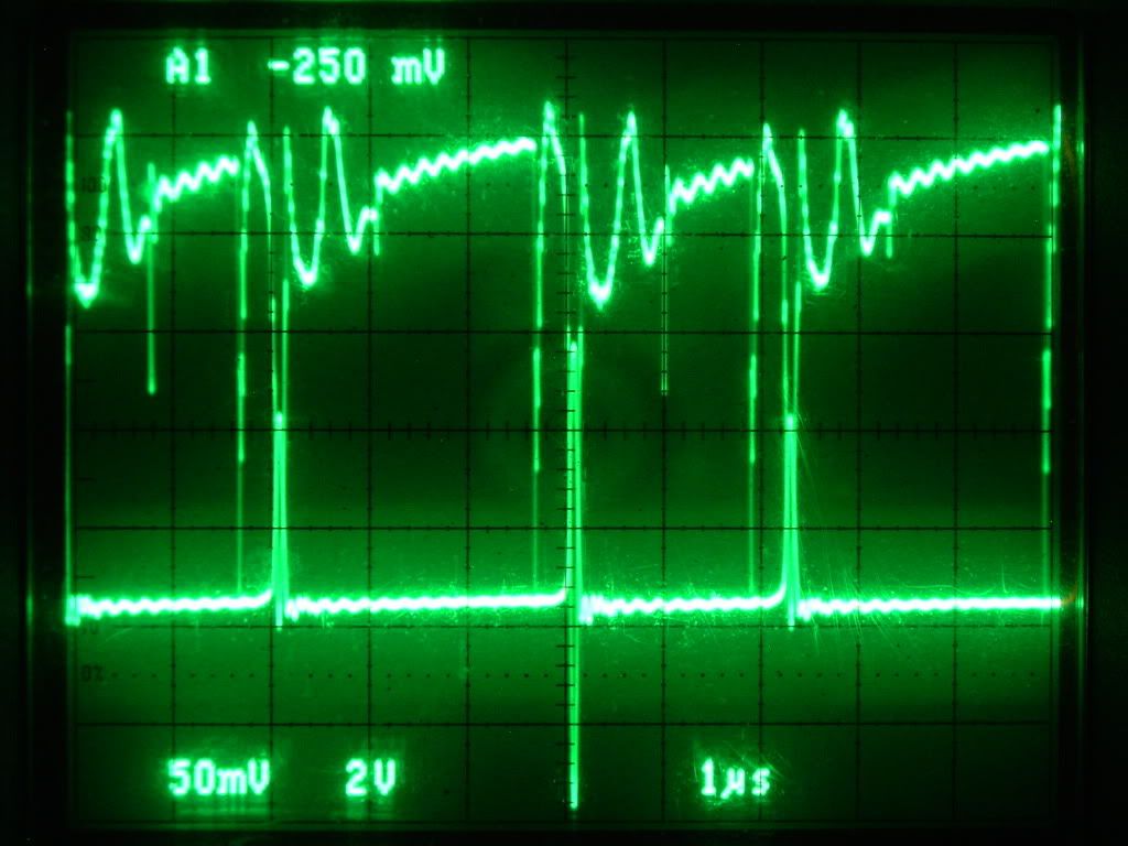
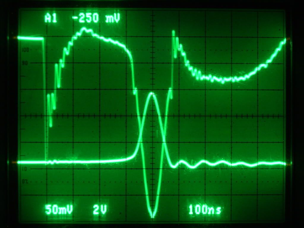
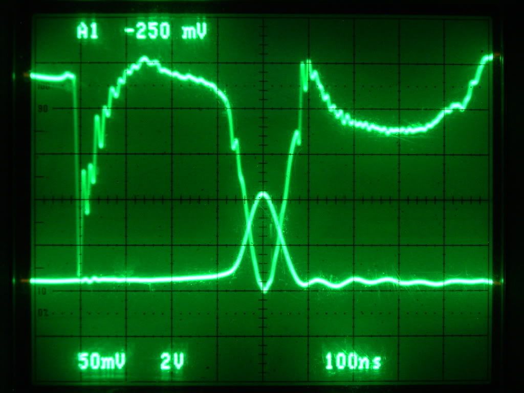
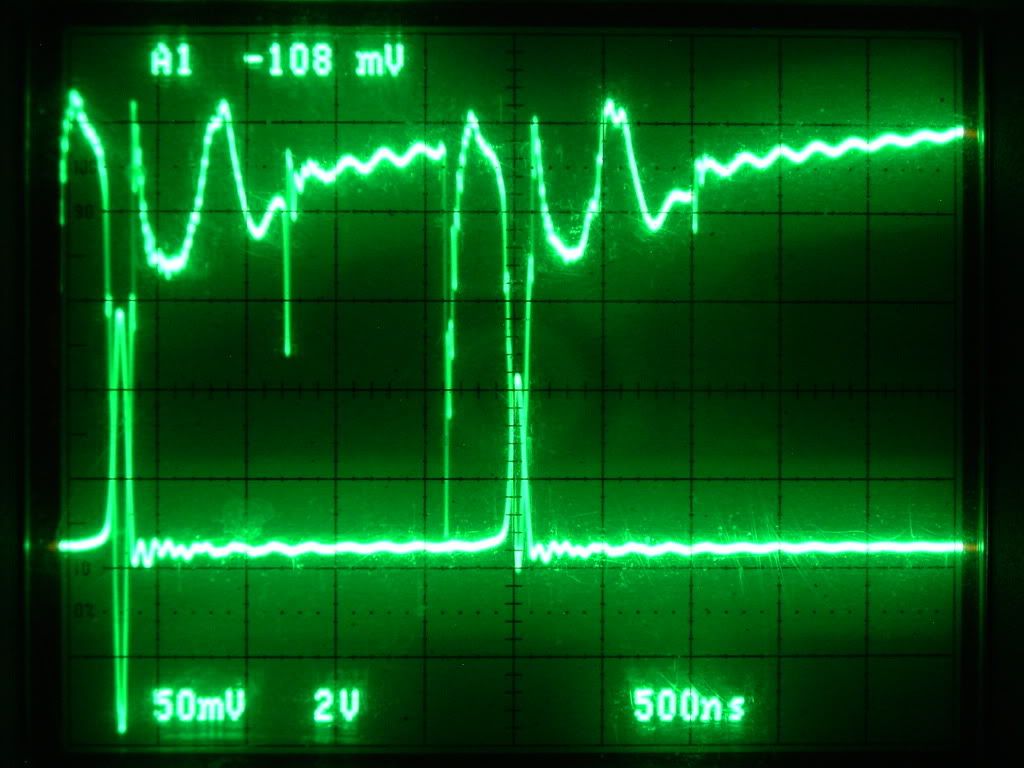
Interesting reading Rose!! [Hacking] Hmm!! The more they do the more they will reveal themselves. Thanks Glen got your PM and thanks Harvey /ALL. Did some more tests just getting a report ready and updating the doc for all. Will have Glens revised one to add to the report also. Thanks Glen
AshComment
-
Already implemented and sold as ethernet over powerline:Originally posted by Harvey View Post
Run Ethernet through Your Walls with the Existing Power Lines in Your Home - CAT-5 TO AC POWER LINE ADAPT
Linksys PowerLine AV Ethernet Adapter Kit PLK200 - bridge : Read product information and write a Linksys PowerLine AV Ethernet Adapter Kit PLK200 - bridge review
That is very high frequency low voltage low current over low frequency high voltage high current.
In Indonesia the national power company already implement this for internet connection for their branch office where electricity can reach. The data home meter gathering can also directly send by newer home metering to their server from powerline. If you never have power company people checking your meter, it is high chance that your meter act as reporting modem too.
As for theoritical explanation, I believe that what move in the wire move in spiral. Unlike common explanation that electron move between nucleus orbit, I believe that the thing move in stream, seeking the natural path just like river, where it rotation diameter will become bigger and bigger, thus making them move close to the skin. Eddy current is side effect of them since they are now rotating the center. To force them to move fast, I think Viktor Schauberger way of making the water move faster may also work.Last edited by sucahyo; 10-26-2009, 05:17 AM.Comment
-
Hi Sucahyo,
Thank you for sharing that information.
We also have available the inverse, Power over Ethernet where remote devices can be powered by a bias voltage supplied on the Ethernet wires.
One of the things I am proposing here is that the power can be the same for both types of current resulting in a net zero condition. That is part of what I was contemplating and opening up for discussion.
Cheers,
"Amy Pond, there is something you need to understand, and someday your life may depend on it: I am definitely a madman with a box." ~The DoctorComment
-
I don't think that is the case. From what I know Cisco use the term power over ethernet by using normally unused number 7 & 8 leg of the cable to transmit DC power to remote location. Both switch must have power over ethernet specification or one of them may break.Originally posted by Harvey View Post
I see. My mind can't reach that I guess. Maybe sort of two sound entering one chamber. They may weaken or strengthen or may not interrupt each other.Originally posted by Harvey View PostComment
-
Hi Sucahyo,
IIRC, 100Mb Ethernet only uses 2 of the pairs of a Category 5 cable, whereas 1Gb Ethernet uses all four pairs of a 5e or or higher category. Thus, if you want PoE over Gb Ethernet, the data must share the same wires with the power. For more information on the 802.3af standard see this, or if you have IEEE access; this
Imagine if you can 1KV at 1A moving on the conductor skin in one direction, spiral vortex and a 20V 50A moving in the center of the conductor, opposite spiral, opposite direction. Imagine that the frequency of each is such so as to provide a perfect magnetic interlace where each spiral crosses the other near right angles - sort of like the weave of a Litz wire. Would the result offer no resistance to the counter flow of current?
"Amy Pond, there is something you need to understand, and someday your life may depend on it: I am definitely a madman with a box." ~The DoctorComment

 Tweet
Tweet


Comment