This forum is preserved as a permanent archive. The community continues at eMedia Press.

Announcement

Collapse
No announcement yet.

COP 17 Heater | Rosemary Ainslie

Collapse
This topic is closed.
X
This is a sticky topic.
X
X
 
  • Filter
  • Time
  • Show
Clear All
new posts

  • ashtweth
    replied
    The PDF is looking pretty good now thanks to you my friend Alex thanks for the advice Bro, thats easy to try, winding Glens inductor now. ill get onto it ASAP my friend.I have a contact at the university, with some equipment will try and match Aaron's and Glens test for Rose/ALL.

    Ash

    Leave a comment:


  • FuzzyTomCat
    replied
    Originally posted by Harvey View Post
    Hi Glen,

    4:00AM here, and I still need to hit the racks, but I wanted to stop in and see how things were going.

    One thing I would like to see: Could you widen that view of the negative pulse on the Source? I am particularly interested in the activity of the source just as the body diode enters conduction. I see there is some cancellation going on there, but it is all too narrow to determine the progression.

    Thanx again for all this. Hopefully when I awake I can get a look at the CSV stuff.

    Cheers,

    Hi Harvey,

    Here is the Images from the Tektronix TDS 3054C and Data files you requested

    555 TIMER "OFF" 360 VOLT SPIKE

    200ns 360 Volt 555 Off .XLR Spread Sheet File


    40ns 360Volt 555 Off .XLR Spread Sheet File


    40ns 360 Volt Spike .XLR Spread Sheet File


    Glen

    Leave a comment:


  • witsend
    replied
    Hi Fuzzy. Yet again. THANK YOU FOR THESE AMAZING RESULTS AND FOR THE HARD WORK IN COLLATING IT ALL.

    I spent a frustrating day trying to open the files with rapidshare. It gets into a loop. I hope it's easier at your end. Eventually got this opened by Carine at Tektronix (SA) - but she could only post this on Skype. She also had some considerable difficulty with the free number. Eventually opened with the 'member?' option. It's complicated but my Skype is on the wrong computer. Any help here would be most appreciated.

    I also paid some tribute to your skills here at OU.Com. But - for the record - I am just so impressed with your professionalism in the way you present the data. And can't wait to do the analysis.

    Still the coolest cat on the block.

    Leave a comment:


  • Harvey
    replied
    Hi Glen,

    4:00AM here, and I still need to hit the racks, but I wanted to stop in and see how things were going.

    One thing I would like to see: Could you widen that view of the negative pulse on the Source? I am particularly interested in the activity of the source just as the body diode enters conduction. I see there is some cancellation going on there, but it is all too narrow to determine the progression.

    Thanx again for all this. Hopefully when I awake I can get a look at the CSV stuff.

    Cheers,

    Leave a comment:


  • FuzzyTomCat
    replied
    Rosemary Ainslie COP>17 Heater Circuit - TEST #2

    Hi everyone,

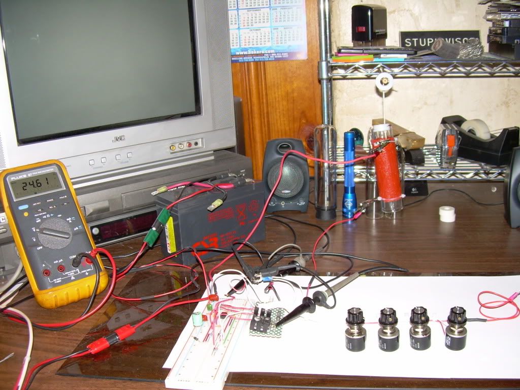
    Here is the second test of the Rosemary Ainslie COP>17 Heater Circuit replication of the "Quantum" October 2002 article.

    It also includes a set of Mosfet Drain 360 Volt spike images and data (spread sheet) .CSV files


    All Images and data from the Tektronix TDS 3054C from the Tektronix Corporation

    TEST #2

    Rosemary Ainslie COP>17 Heater Circuit
    "Quantum" October 2002


    Replication Components -

    1)
    w/ Sil-Pad insulator between Mosfet and Heat Sink

    2) Fairchild Semiconductor - NE555N Timer

    3) Vishay Spectrol - SP534 Percision Potentiometer/ 10-turn 2-Watt

    4) Exide Technologies Battery "Liquid Lead Acid" Model # GT-H - TRACTOR 12V 12Ah CCA 235

    5) CSB Battery Company "Gel Lead Acid" #GP 1270 F2 / 12 Volt 7.0 Ah

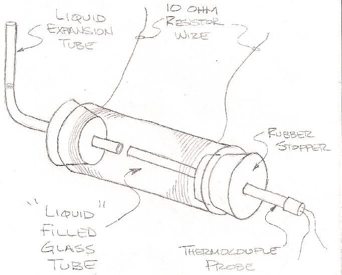
    6) Prototype - 10 Ohm resistor "Quantum Replication"


    Temperature Measurements -

    Fluke 62 "mini" IR Themometer ( used maximum reading on each componenet )

    Digital Mulit Meter -

    Fluke 87 DMM true RMS

    -------------------------------------------------------------------------

    Channel 1 - Mosfet source shunt
    Channel 2 - Mosfet drain
    Channel 3 - 555 Timer pin #3
    Channel 4 - 24 VDC "Liquid" Lead Acid Battery Bank


    2us Start
    *Original 2us "Start" .XLR Spread Sheet File
    2us_start .CSV file


    20us Start
    *Original 20us "Start" .XLR Spread Sheet File
    20us_start .CSV file


    2us Finish
    *Original 2us "Finish" .XLR Spread Sheet File
    2us_finish .CSV file


    20us Finish
    *Original 20us "Finish" .XLR Spread Sheet File
    20_us_finish .CSV file


    TEMPERATURE DATA SHEETS -


    2us 360 Volt Spike
    *Original 2us "360 Volt Spike" .XLR Spread Sheet File
    2us_4_chan .CSV file


    1us 360 Volt Mosfet Drain Spike
    *Original 1us "360 Volt Spike" .XLR Spread Sheet File
    1us_4_Chan .CSV file


    400ns 360 Volt Mosfet Drain Spike
    *Original 400ns "360 Volt Spike" .XLR Spread Sheet File
    400ns_4_chan .CSV file


    Glen
    Last edited by FuzzyTomCat; 10-08-2009, 02:51 AM. Reason: added .XLR files

    Leave a comment:


  • witsend
    replied
    elias - MANY THANKS FOR THE TEST. Your pictures are amazingly sharp. I'm afraid I'm not sure how to advise you on your test data evaluation. I'm hoping Aaron can oblige or someone? Failing which I'll try and get back to you tomorrow.

    I love your recommended energies btw. And again. Thanks very much for the input here.

    Leave a comment:


  • elias
    replied
    Originally posted by witsend View Post
    Great stuff. Btw - I see you're hardly a new member? Just new to this thread. Sorry about that. It looks like I'm actually the newbie here.
    This thread was in my mind in a corner and i also read your theories about zipons and so on, I have been so grateful. Your theory about a universe being created from a single infinitesimal God particle totally resonates with me. This forum has been a wonderful place for me to learn and grow.

    People like you have made this forum a wonderful place to be.

    Leave a comment:


  • elias
    replied
    My first replication

    Hi,

    I finally replicated it yesterday. I used a 12 volt DC adapter and my current meter was showing 0.51A at 50% duty cycle 24KHz set on my signal generator. The resister warmed up in about a minute and I suppose it was around 70 degrees Celsius. Because it was hot to the touch, as I couldn't hold my fingers on it for more than 2 or 3 seconds. I don't have thermometer yet, so I couldn't make accurate measurements.

    I used a 20% duty cycle signal at 2400Hz, and I could get the resistive element to warm up in the first minutes. I have to get a thermometer.

    Here are the pictures:


    Rosemary,
    I wonder about measuring the heat? Can you offer an easy way to measure the Heat Energy output?
    This was an interesting experiment, as it can be scaled up so easily.

    I also used my 18v adapter, and this made the resistive inductive element get pretty hot, as it was giving off noticeable heat. The current was 0.8A in this case.

    Thank you
    Elias

    Leave a comment:


  • jibbguy
    replied
    Hi Fuzzy,

    Excellent work, m8.

    Looking at your drawing, i was wondering what you are going to attach that thermocouple to.

    A "J" or "K" TC would probably be the most accurate means available for these temp ranges, but as far as i know, they always require a separate Signal Conditioner / Amplifier box to get a linear output. This is because their voltage output per degree is "naturally" non-linear, and the calibrated signal conditioner, set for the specific type of TC, has the proper table built in to "linearize" the output. Otherwise, it is a bit of a nightmare to use the table & manually do the calcs to get the temps right from the V output (... although it is possible to do, the tables are available).

    So unless you have a TC signal conditioner, you may consider using a thermistor instead, like the DMM options, as they have linear outputs and can be used without a separate "front end" signal conditioner more easily.

    Last edited by jibbguy; 10-04-2009, 11:00 PM.

    Leave a comment:


  • quantumuppercut
    replied
    Fuzzy,

    Very nice and neat. Sorry I missed that post.

    Leave a comment:


  • FuzzyTomCat
    replied
    Originally posted by quantumuppercut View Post
    Hi all,

    Could someone fill me in on the procedure measuring heat for this experiment? I saw the logging on ambient temp and component temps. Does this means we're using air as a medium to measure dissipated heat? Thanks.
    @ quantumuppercut

    At The present time my only method is to do temperature measurements in ambient air using a Fluke 62 "mini" IR thermometer .... to do surface tests of components and using the "Maximum" temperature reading on each component for recording purposes .... although I have shown a alternate method for my prototype
    Quantum 10 ohm "Load Resistor" a method in a earlier posting here at Energetic ..... I don't know at this point before more data is acquired from the planned tests I have if this will be possible or useful prior to returning the TDS 3054C oscilliscope to the Tektronix Corporation thats on loan ....


    Glen

    Leave a comment:


  • FuzzyTomCat
    replied
    Originally posted by Harvey View Post
    Glen!

    Fantastic - really good work there. Great record keeping to boot

    This is exactly what I was expecting on the Drain and Source, I can't express my thanks enough for what you've shown. And that negative spike perfectly aligned with the gate falling edge , so glad you moved the marker over on those shots so we could really see it's full impact. That one is the capacitive gate-source feed through that occurs 1.3 divisions before the inductive collapse. Very interesting how well that passes through there. But the Drain and Source activity after the FET is off, that is the really interesting thing.

    As the magnetic field collapses around the load resistor the Drain spikes to what, 220V? That is a positive going voltage. At the exact
    Hi Harvey

    Thanks for the words of encouragement ...... any other information or data you may need just ask. I thought also mentioning the data on my Mosfet "shunt" resistor is a "Dale" RS-2B / .25 ohm / 3 watt / 3 % tolerance

    The 220 volt spike on the Mosfet drain .... where it comes from .... and where it goes .... could be the question of the day

    Glen

    Leave a comment:


  • quantumuppercut
    replied
    Hi all,

    Could someone fill me in on the procedure measuring heat for this experiment? I saw the logging on ambient temp and component temps. Does this means we're using air as a medium to measure dissipated heat? Thanks.

    Leave a comment:


  • Harvey
    replied
    Great Results

    Glen!

    Fantastic - really good work there. Great record keeping to boot

    This is exactly what I was expecting on the Drain and Source, I can't express my thanks enough for what you've shown. And that negative spike perfectly aligned with the gate falling edge , so glad you moved the marker over on those shots so we could really see it's full impact. That one is the capacitive gate-source feed through that occurs 1.3 divisions before the inductive collapse. Very interesting how well that passes through there. But the Drain and Source activity after the FET is off, that is the really interesting thing.

    As the magnetic field collapses around the load resistor the Drain spikes to what, 220V? That is a positive going voltage. At the exact

    Leave a comment:


  • rave154
    replied
    AWESOME stuff there tomcat !!!!

    Leave a comment:

Working...
X