
No one is interested in a fight, least of all me. I have ceased all activities which could even remotely be considered as hostile days ago and have apologized profusely.
People may be silent, Eric, but I assure you that all eyes and ears are on you.
Your efforts and those of Lamare are admired and appreciated by all on this forum.
Carry on
Orion
-
Lamare Dialogue
It is great to find a point of discussion, the Energetic Forum has been very boring to me, like talking to my own echo. However bickering like that with Light Ship seems to be more what interests everyone, a good fight!
When considering waves on coiled windings, leave out the electrons, let us forget them once and for all. They are for electronic devices (RG) NOT for electrical devices (LC). Forget the electrons, forget it!
It is generally considered that any wave must consist of a conjugate pair of energies, magnetic and dielectric let's say. Only then an interaction between time and space is possible. As I have shown recently it is through the union of a conjugate pair (L and C) that the dimension of time is produced. The propagation constant is then equal to:
(1) Negative Gamma Square
Having a pair of imaginary roots, plus j Gamma and minus j Gamma
It is however that the JJ Thompson Longitudinal Dielectric Motions cannot have a periodic solution, there is one energy only, dielectric. This needs to be resolved.
There are four distinct forms of energy stored in a winding,
Magnetic Pair:
L, Leakage Inductance, Henry
M, Mutual Inductance, per Henry
Dielectric Pair:
C, Leakage Capacitance, Farad
K, Mutual Capacitance, per Farad
The Magnetic Distribution along the coil axis is given by
(2) Epsilon to the square root of LM power. It is an exponential curve along the axis.
The Dielectric Distribution along the coil axis is given by
(3) Epsilon to the square root of CK power. It too is an exponential curve along the axis.
LM an CK are time scalars hence it can be seen that these initial distributions at t = 0 give rise to complex energy exchanges because of the exponential space distributions. We have now a fourth order differential in space and time. Alice lands in Wonderland. Forget Maxwell, forget the Corums, dead ends, forget them once and for all!!
Break, more to follow
DE N6KPHLeave a comment:
-
Today, I made a new probe according to the new design:
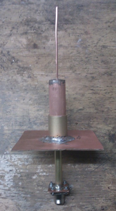
I used a 5 cents coin to close the top of the sleeve and solder the coax feed line in. For the ground plane reflector I used a piece of PCB, where I scratched away the copper from the center, while the dielectric material gives some mechanical support to the coax feed line. I took that one 15 cm, which should be a half wave length, considering the propagation speed factor of the aircom plus dielectric which I used in the coax feed line, which is a piece of 10 mm diameter 0,6 mm thickness copper tube, where the dielectric and core of a piece of Aircom plus coax fits very nice.
The length of the sleeve is adustable, because it can move back and forth within the socket. And the length of the whip is also adjustable, because I added a tube that fits just around the core of the coax, which can move back and forth around the whip.
More photos here with some construction details:
Dropbox - Photos - Longitudinal_Probe_V2Last edited by lamare; 01-03-2012, 02:51 PM.Leave a comment:
-
Originally posted by T-rex View Post
You are right in that these are not standard transverse E.M. waves aka "Hertzian waves", BUT they all are E.M. waves because they all have a magnetic component. I think the dielectric longitudinal wave does not have a magnetic component. In other words: it does not create rotational disturbances in the ether a.k.a. the magnetic field. At least they should be much smaller in magnitude.
Some time ago, I made an analysis of how waves propagate along a coil:
Article:Free Electric Energy in Theory and Practice - PESWiki
So, we are looking for a propagation mode without magnetic component, which is a different mode than a TM mode, since a TM mode still has a transverse magnetic component along with a longitudinal electric component, which eventually is why the TM mode will almost certainly still propagate at a speed of c, and not pi/2 times c.Let's look a bit deeper into resonating coils. As I stated before, Stifflers circuit resonates a coil at a multiple of its natural ground resonance frequency. Since the coil windings have a parasite capacitance towards one another, part of the electric energy, which is a wave, travels across these capacitances.
Usually, these parasite capacitors are only considered as a whole in order to calculate the natural ground resonance frequency of a coil. But they are very significant when we want to understand what happens with Stifflers circuit, the Joule Thief, Stanley Meyers stuff and all other resonating free energy coil systems.
I have been thinking about this for quite a while, but up to yesterday, I never understood what is actually happening inside a coil and wondered wether or not you could get the same effect by putting a bunch of caps in series and put those in resonance.
Then I realised that a coil wire is round and that the current, the electrons, actually travel across the surface of a wire. If we only consider the longitudinal component of the resonating waves along a coil, we are looking into the electrical wave traveling along the coil, perpendicular to the coil wires. In other words: we consider an electrical component that travels perpendicular to what we usually consider the direction of the currents going trough the wire.
I made some sketches which I have attached. The first page is just a rough sketch with some notes illustrating my line of thinking, but not much more.
If you take a look at the second pge, you see at the top-left two parts of coil windings, with at the top-right a model made up of capacitors, which is how you would usually think about these kind of things. If we consider the wire in the model connecting the different capacitors, and consider a current going trough there, you will have a magnetic field H curling around the wire.
However, the real parasite capacitors at the surface of coil wires are not at all connected to one another with straight wires. It’s a round surface, so the electrons will make curves, spirals, moving between the “capacitor plates”. So, you won’t get a H field curling around, but you will get an H field in parallel with the coil wires!
When I made this second page, I assumed there would be a resulting current spiraling around the surface of the wire. Then I realised that there is actually no reason to assume this spiralling current to have any preference for a particular direction. In other words: half of the electrons traveling between the capacitor plates will go in one direction, the other half will go in the other direction. And that is very interesting, since we now have an electric field propagating between the coil windings, *without* a resulting magnetic field!!!
And, if there’s no magnetic component, there’s no Poynting vector, and therefore no radiation of energy…
Very interesting, because this might give us some hints on how to make signal guides for longitudinal electric waves. One tends to think in the direction of putting several isolated wires in a row. Then, you would have the capacitive coupling to propagate the energy, while the spiralling currents prevent any magnetic component to spring up and radiate our precious energy away into outer space……
The sketches, page 2:

Conclusion: The longitudinal component of the wave across coil windings has the magnetic field component H in parallel with the wire, while the current moves perpendicular to the coil wire, across the surface. In order words: when f goes to infinity, the external supplied current goes to zero.
Page 3:

There is no reason to assume there is a difference between I_l and I_r. Probably 50% of the electrons go left, 50% go richt. So, H_left == H_right. Or: H_result == 0.
Conclusion: Because of the shape of the coil wires, a pure electrical wave is possible, without magnetic component and without et electrical current to feed in from the outside.
Also see: The L.M.D./T.E.M.Test
It is interesting to look at the probes they are using with the TM mode (left part of fig 129):
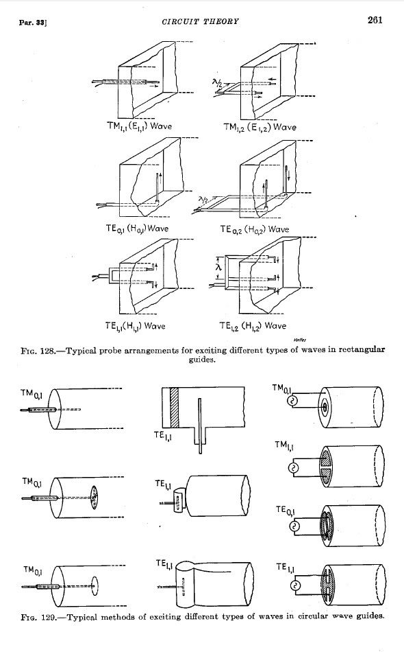
It looks like they are also using a sleeve balun, only this one is placed at the outside of the wave guide, while the ground / reflector plane is at the feed point, at the point where your feed current activates your wave, which means eddy currents, etc. will be induced in the plane, which appears to be the mechanism to create the conditions for a magnetic component to propagate along the surface of the pipe.
I suspect that when I place the ground/reflector plane at a tip of a dipole, where there is no current in the propagation direction, that you can get rid of this magnetic component, at least to a much larger degree than with the feed used for the TM modes.
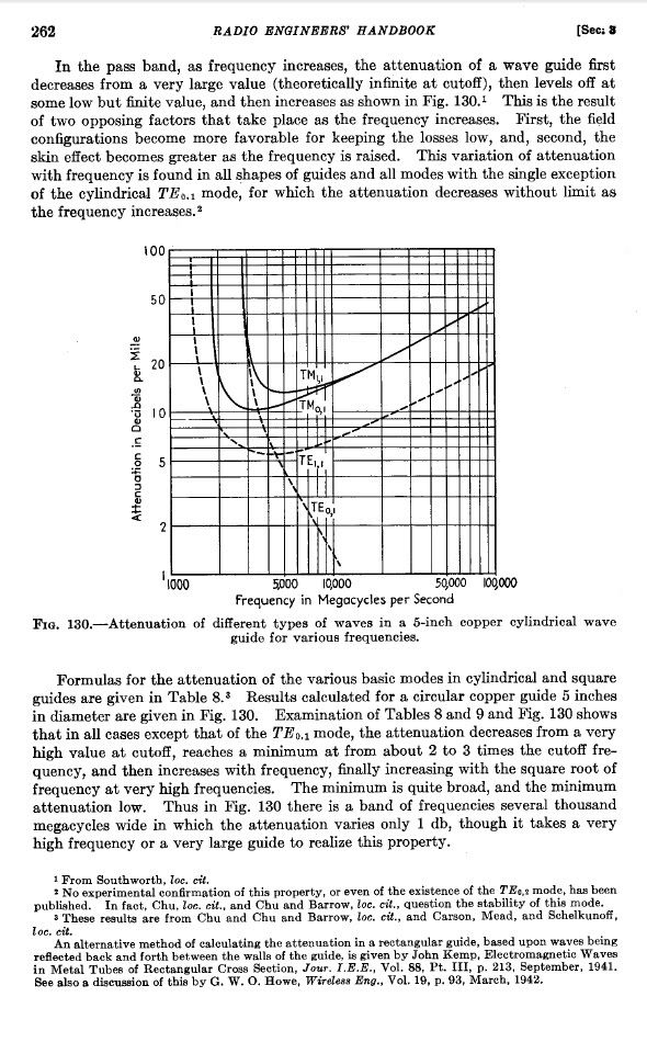
I think the mode we're after is a mode without magnetic component, which I think is actually very easy to excite with the proper probe, because the diameter of the pipe is one of the most important parameters in all these E.M. modes, because the conductor surface has to support the magnetic component, which is why only certain diameters work.The longitudinal antennae ideas seem stuck in the mud. Seems everything is quasi E.M. "Electrical Soundwaves in the Aether", Tesla. Only two ways I see; a form of open ended circular waveguide. One mode, hard to excite, is longitudinal. Please post circular waveguide mode chart (Frederich Terman)!!
However, for the longitudinal dielectric mode, the diameter is not critical at all, just like in the acoustic world of Helmholtz. So, any diameter that is smaller than required for any E.M. mode to propagate should do.
Leave a comment:
-
Just trying to post some correction of facts. I read the entire Terman book 3 or 4 times.Originally posted by lamare View Post
These are NOT Transverse E.M. waves, THEY ARE NOT!
Mind Virus Cancellation:
Tm (m is subscipt), Transverse Magnetic
A.K.A.
Ld (d is subscript), Longitudinal Dielectric.
Also,
"Te" = "Lm", etc.
Your "Tm(subscript) 01" Good Idea "Ld(subscript)" Longitudinal Dielectric.
That "Te(subscript) 01" fascinates me!
But don't let me distract you
Good luck with the...
Lamare Lunar Initiative, L.L.I.Leave a comment:
-
These are all transverse electro magnetic modes. The dielectric longitudinal wave we are after is the one without magnetic component. The mode missing in ALL the textbooks I have seen this far.Originally posted by T-rex View Post
We will see where this goes. I have the feeling that with my sleeve balun design we have a pretty good chance of success. So, I'm going to build one and if all goes well, I will have it tested at january 14th, 2012. Then there is a "measuring day" well known by the best radio amateurs in North Western Europe, where there is equipment available the avaredge radio amateur can only dream of.
So, wish me luck!


-- Arend --Leave a comment:
-
Lamare Lunar Effort; Ideas
The longitudinal antennae ideas seem stuck in the mud. Seems everything is quasi E.M. "Electrical Soundwaves in the Aether", Tesla. Only two ways I see; a form of open ended circular waveguide. One mode, hard to excite, is longitudinal. Please post circular waveguide mode chart (Frederich Terman)!!
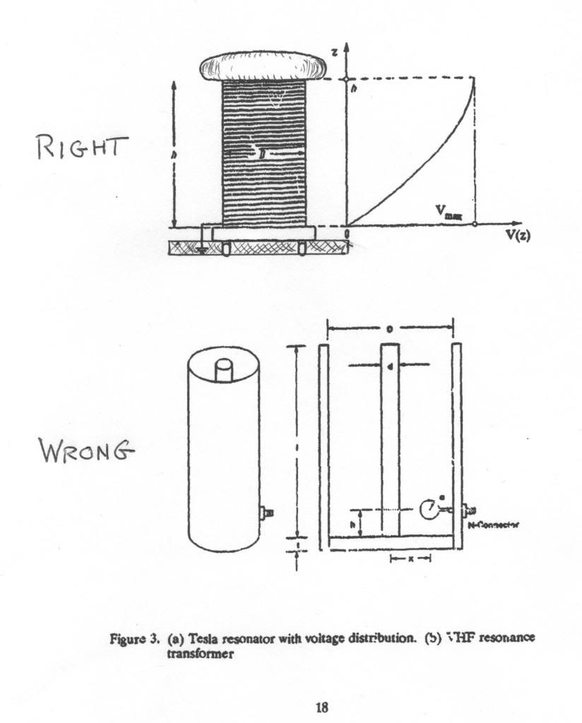
Another way is a tiny U.H.F. resonant coil, NOT A HELICAL RESONATOR. AN OPEN COIL NOT ENCLOSED IN A COAXIAL CYLINDER.
For the circular waveguide the pipe is closed on one end, open at the other end. Open end may require mode stabilizer. The proper mode of excitation is extremely important! (Terman, Radio Engineers Handbook)
For the resonant coil, a disk larger than coil diameter at current end, a disk smaller than coil diameter at voltage end. Ratio of disk diameters derived from coil impedance. Excite coil with small loop. As for the frequency; For the waveguide must be greater than 1000 Mc, for the coil must be less than 1000 Mc. These would be my first efforts to create electrical soundwaves in the aether. The longitudinal waves of my work involves Telluric Waves (submarines) and windings (transformers). Free space longitudinal waveforms may not have any relation to my (MK) wavesLast edited by t-rex; 12-26-2011, 10:19 PM.Leave a comment:
-
Originally posted by Kokomoj0 View Post
The idea is to drive the antenna with an ordinary transmitter, while the antenna's are supposed to resonate like a self resonant coil. In essence, the whip is also a coil because of the self-inductance of the wire. Eric's input is posted here as well as on the other thread. He pointed a.o. at Helmholtz' equations and Steinmetz, which offer some guidelines and insight, but the specific design in the end is a matter of trial and error.
Anyway, we have tested the first prototypes and they were NFG. The basically did nothing even close to what was intended and I think the cause of that is that I should not have used a 1/4 lambda whip on top of a reflective ground plane, because the ground plane is located at a current hot spot, maximal movement of charge carriers, while actually no current can flow trough the reflective ground plane in the direction along the length of the whip.
So, as far as I can tell now, I have to adapt my probe (as it is called) from a 1/4 lambda whip into 1/2 lambda dipole, which is fed from the centre. I made a drawing of what I intend to do:
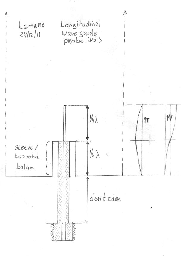
The idea is to use a radiating "sleeve" or "bazooka" balun, meanwhile preventing the coax mantle to radiate:
What about a balun?
Note that longitudinal waves are supposed to propagate along the axis of the whip and coax feed line....>Why is it some antenna's have baluns and others have not?
The purpose of a balun is to prevent the coax cable from radiating. However, in order for the coax to radiate, there would need to be some radiative component along the axis of the coax to induce current in the coax. A symmetrical biquad doesn't have any such field component. Therefore, a balun is not needed.
However, things get a bit different when the balun is used to feed an offset dish. The field is no longer axially symmetrical, and the coax is in the reflected field from the dish. Therefore a balun is probably a good idea with a dish.
In general (with lots of exceptions), when the coax cable is in the antenna field, you need a balun. The real question is how much difference does it make? Most of the effect is in reducing VSWR, not increasing gain. With relatively low gain antennas (i.e. biquad with 10dBi gain), it probably might improve things perhaps a few tenths of a dB and is not worth the effort. However, with higher gain antennas, such as a dish, the lack of symmetry caused by a radiating feed could easily distort the pattern, create sidelobes, boresight errors, and VSWR.
Also, some antennas are best constructed with 200 ohm feed points (i.e. Franklin antenna).
Sector antenne voor Wifi ISM band (2,4GHz)
Adding a 4:1 balun solves the balance problem and the impedance transform problem at the same time. You may therefore see a balun on some symmetrical antennas that don't normally require one, but where the impedance transformer action makes one convenient.
Dipole antenna - Wikipedia, the free encyclopedia
At VHF frequencies, a sleeve balun can also be built to remove feeder radiation.
* Another narrow band design is to use a λ/4 length of metal pipe. The coaxial cable is placed inside the pipe; at one end the braid is wired to the pipe while at the other end no connection is made to the pipe. The balanced end of this balun is at the end where the pipe is wired to the braid. The λ/4 conductor acts as a transformer converting the infinite impedance at the unconnected end into a zero impedance at the end connected to the braid. Hence any current entering the balun through the connection, which goes to the braid at the end with the connection to the pipe, will flow into the pipe. This balun design is impractical for low frequencies because of the long length of pipe that will be needed.
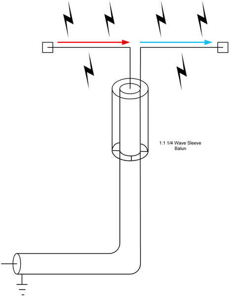
Sleeve baluns
http://web.archive.org/web/201007170...io/sleeve.html (copy here: sleeve1 )Depending on which layout is mechanically easier to build and if you want the sleeve to radiate, the sleeve can be connected like this or reversed. In the layout below the sleeve is non-radiating. In a collinear antenna we might want to reverse the sleeve so it forms half of a dipole element.
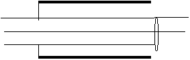
[...]
From the above, we observe the following characteristics in a sleeve balun:
1.) The highest possible choke sleeve impedance (largest ratio of balun sleeve diameter to outside of transmission line) is desired. We won’t have a good balun if the choking Zo (ratio of sleeve inner diameter to coaxial shield outer diameter) is small.
2.) The balun requires the lowest possible loss over the length of the sleeve. It forms a transmission line from the inside of the sleeve to the outside of the coax. The coax jacket is a dielectric, so we need to keep a lot of air inside of the choking sleeve or the coax jacket will increase loss and reduce impedance, both being very undesirable.
3.) The velocity factor of the sleeve, based on the dielectric between the sleeve and the shield of the coaxial cable we are trying to balance or choke, is very important to length of the sleeve.
The following construction guidelines apply:
The cable should have a good low-loss jacket or a very large air or low loss dielectric gap between the shield and the sleeve. Since energy is normally confined to the inside of a coaxial cable manufacturers are not concerned about jacket losses. They use outer materials with long life, not low RF loss. It is advisable to use a filler material with a high volume of air to maximize sleeve impedance and minimize sleeve losses.
It is also advisable to use the largest practical diameter sleeve with the smallest diameter coaxial cable inside to maximize choking impedance.
The sleeve length has to account for velocity factor of the sleeve, since the sleeve forms a coaxial transmission line with the outer conductor of the coaxial cable it is intended to choke or decouple.
What's this weird antenna called? - RC GroupsThe sleeve balun does not give any impedance transformation; it is a 1:1 balun. This is fairly easy to achieve at VHF. All that is required is a tube that is coupled to the outer of the coax at approximately 0.93 X l/4 from the antenna feed point.
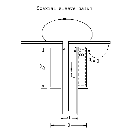
The ratio D/d should be around 2.5 to 4. The open end of the tube facing the antenna element should be as close as possible. In effect this tube is a shorted l/4, at it open end the impedance looking back down the coax is high, thus preventing RF current developing on the outer of the coax.
I have made sleeve baluns using 15 mm copper water pipe and soldering a 'Free socket N' type connector onto it. The l/4 may be less than that of free space l/4, because of the close proximity of the outer tube to the coaxial cable. I found that 468 mm seems to work OK at 2 m, when using RG213 or URM 67.
Note that the presence of a dielectric in between the outer conductor and inner conductor influences the propagation speed of the waves, which means the length of the sleeve must be adapted to that. And indeed, it is better to have some space between the inner and outer conductors, which is preferably air in our case, since we want the outer conductor to be part of our 1/2 wave dipole....What people wanting DIY a sleeve balun should know, is the fact that the sleeve must be at some distance from the coax, and this empty space must be air, not a plastic insulator !
The RC-cam antenna done using the coax mesh to simulate sleeve balun is one of the most popular but flawed example of how to not make this, because the balun part is so close to coax, making it zero efficiency.
[...]
Not quite correct. The distance between the outer conductor and the inner conducter need not be air. It can be any dialectric or insulating material, it is just that the spacing has to be adjusted to accommodate the dielectric constant of that particular insulation material.
[...]
The thing weird revealed:
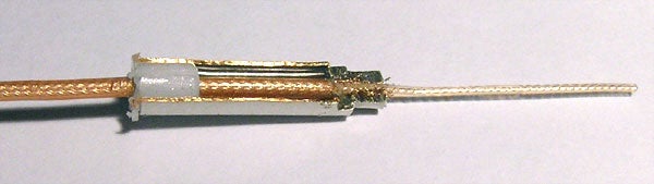
Also see:
Antenna Theory - Bazooka Baluns
So, another build & test phase...
For now:
Merry Christmas to all!Last edited by lamare; 12-26-2011, 03:08 PM.Leave a comment:
-
I know little of antenna design, except to watch the reflected power that can blow the finals, something you are already fully aware of, so I have nothing to add except; it looks absolutely great!!! With you 100%
OrionLeave a comment:
-
Prototype cantenna's
Hi all,
Today I finished my two prototype longitudinal cantenna's. Here's a photo of the 1/4 lambda adjustable whip:

And one of the interior of the two finished prototypes:
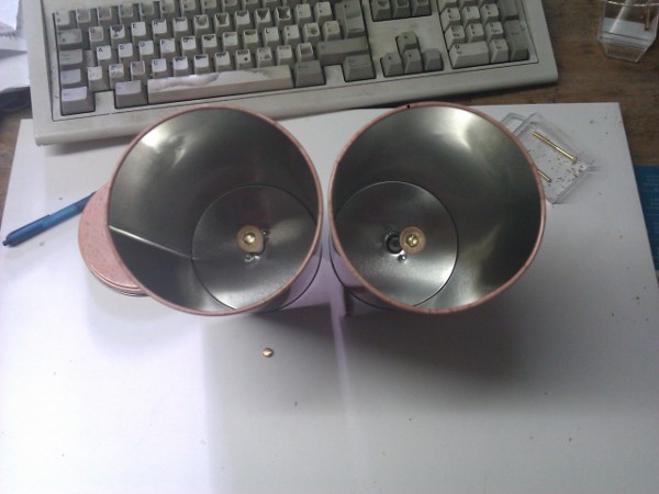
More pictures here:
Dropbox - Photos - Simplify your life
The next phase will be testing and tuning, which may take a couple of weeks, depending on the availability of the required equipment, the amount of adjustments needed, etc.Last edited by lamare; 12-19-2011, 03:56 PM.Leave a comment:
-
Well, the root argument is about the Maxwell equations. In my article wherein I theoretically disprove Einstein's relativity theory, I essentially say that the electro-magnetic field is the cause for matter to exist and not the other way around, completely in line with Quantum Mechanics, which is incompatible with Einstein's theory, exactly because of the mix-up of cause and effect in the Maxwell equations:Originally posted by exnihiloest View Post
Tuks DrippingPedia : Ruins 96 Years Einstein Relativity
With the correct Maxwell equations, along Meyls and Thornhill (even though I agree there's a lot to argue about with Meyls experiments, but that's not the point here), longitudinal dielectric waves are predicted, which count as "experimental results predicted by an aether theory differently from current theories".
And that is what this whole experiment is about. It has to go trough space, because otherwise critics will come up with all kinds of excuses. And the propagation speed difference has to be verified, because of the same reason.
So, if this experiment succeeds, we have undeniable proof that Einstein's theory is wrong and the aether theory predicts the correct results, which it also does in many, many other cases.
I have yet to see an experiment that really disproves the aether theory. The null result of the Michelson-Morley experiment does not disprove the existence of the aether, it merely disproves some secondary assumptions based on the aether theories of the time:
A Dissident View of Relativity Theory by William H. Cantrell, Ph.D.
And that's what I'm trying to do, performing a "decisive blow".So far, we have at least two competing theories: a partially entrained aether and Einstein’s relativity. Both can explain the results of the Michelson-Morley and Michelson-Gale experiments, the Sagnac effect, (and the Häfele-Keating experiment). But we need a tie-breaking experiment for it is not good enough to merely come up with an alternative theory. We need a decisive blow.
Leave a comment:
-
Longitudinal wave can move everywhere : in gas, liquid and solid. Transverse waves can only move in solids ,mostly on the surface or other barrier of those kinds of materials with different speed of propagation of waves. That's my opinion only, need to check it.Leave a comment:

Leave a comment: