Announcement

Collapse
No announcement yet.

Peter, whatever happened with Eric P. Dollard?

Collapse
This topic is closed.
X
This is a sticky topic.
X
X
 
  • Filter
  • Time
  • Show
Clear All
new posts

  • Question for Eric

    Eric:

    Would you have time to explain the 2 types of voltages and 2 types of current to us?

    Also, if the dielectric stores the electrical energy, then obviously it is the ether, because we do have vacuum capacitors. Why cannot people today make the inference? (as shown by the simple MIT video, wherein the metal cylinders were removed, and the glass clearly causes the voltage on the metal, when re-introduced)

    I have a lot of questions that I wish to ask, but the first one is most intriguing to me (and others that I have talked to)

    Thank you.

    Comment


    • Hindrances to true knowledge

      Kokomoj0 posts Oliver Heaviside complaining about the mindset stuck in older people who have a hard time grasping new concepts, whereas the younger generation gets it.

      I think that this is a problem we all face. Once I asked the question of what does a circle in 3d space look like? It took me 2 weeks of hard thinking before I finally came up with an answer. I asked the math head at a local university what a 3d circle was, all he could do is run a symbolic algebra program and give me a 3x3 matrix full of products of sines and cosines which clearly no one could ever remember. I tried other math professors, they gave up. Finally I contacted the chief math editor of one of America's prestiguous math journals. He admitted that he too, could not describe a circle.

      I realized then that original thinking is very hard and original thinkers are hard to come by. For geometry, one original person is H. M. S. Coexeter. As, as someone recently said, and I paraphrase (and agree) "all the rest are parrots"

      Yes, too true. And attitude is a key here.

      I am hoping that we all can be patient. I did come here to learn.

      Thank you.

      Comment


      • Originally posted by Logical American View Post
        Eric:

        Would you have time to explain the 2 types of voltages and 2 types of current to us?

        Also, if the dielectric stores the electrical energy, then obviously it is the ether, because we do have vacuum capacitors. Why cannot people today make the inference? (as shown by the simple MIT video, wherein the metal cylinders were removed, and the glass clearly causes the voltage on the metal, when re-introduced)

        I have a lot of questions that I wish to ask, but the first one is most intriguing to me (and others that I have talked to)

        Thank you.
        I am not Eric, but I think it goes as follows:

        Voltage
        1) E.M.F. as in the development of potential on the secondary winding of a transformer. (E,Weber per second)

        2) Electrostatic Potential as in the dielectric energy stored in a capacitor. (e, Coulomb per Farad)

        Current
        1) Displacement Current as in the current that charges a capacitor. (I, Coulomb per second)

        2) Conduction Current as in M.M.F. or the conventional current that flows continuously in a closed loop. (i, Weber per Henry)


        On a side note, Eric is not working any real job right now. He is spending his time fixing his car and writing for the Energetic Forum. He isn't trying to do all of this for free. Everybody must eat. If he doesn't get some income soon, it is likely that we will not see him around for much longer.

        Dave

        Comment


        • Thanks

          Web000x, thanks for that confirmation, as it is what I expected. I am still amazed that this is NOT being taught in either high school physics and certainly not college/university courses.

          I wonder if perhaps QEX of the ARRL might be a suitable forum for distributing this "oversight" so that more hams and engineers could become aware of the omission (purposeful or not) ??

          Just a thought.

          Comment


          • Originally posted by Logical American View Post
            Web000x, thanks for that confirmation, as it is what I expected. I am still amazed that this is NOT being taught in either high school physics and certainly not college/university courses.

            I wonder if perhaps QEX of the ARRL might be a suitable forum for distributing this "oversight" so that more hams and engineers could become aware of the omission (purposeful or not) ??

            Just a thought.
            I guess it would depend on how open they are to it. I have to keep my mouth shut on the physics boards or get banned for even so much as question the status quo. Sad really, the blind would rather stay blind...paradigm shifts can be bumpy!

            Comment


            • Originally posted by Kokomoj0 View Post


              I had to read that a couple times myself.

              I think he is talking about each?


              Can we think of that as similar to the flat wound amature transmitter coils?


              does any of that sound right?

              So do I read it correctly that we want Hi Z, Low inter-winding C, because that will result in higher magnification?

              I am still plugging away on a couple things in his response to me too.


              So I presume that fence is a huge primary magnetizing coil, the one he is siitting under is the secondary, and the center which is that same height as the secondary I presume is the extra "tesla" coil with the sphere on top?

              @Eric
              is the secondary wire spacing that gets wider toward the top because of poor insulation and high voltage or is that some kind of tuning? both? From what you are saying it sounds like we would want that secondary to be close wound and also the extra tesla coil with the sphere on top to be close wound? The primary I remember you mentioned using strap bronze for good impulse response.

              Maybe I should be asking what we are all looking at in that pic That sphere almost looks out of place? and the center does not look like coil but a pipe. Like the center of a transmission line?
              .
              The fence is a single turn primary and a 22 turn secondary. Primary and secondary windings have the same weight. The size of wire used in both is 8 gauge. Obviously paralleled in the primary into one large conductor. The extra coil is wound with #10 wire. More specifically equal width to height ratio and the extra spacing on the outer turns is due to the accelerated voltage gradient. All of your odd harmonics add up at this point, and produce an enormous rise in electrostatic potential.

              SUPPORT ERIC DOLLARD'S WORK AT EPD LABORATORIES, INC.

              Purchase Eric Dollard's Books & Videos: Eric Dollard Books & Videos
              Donate by Paypal: Donate to EPD Laboratories

              Comment


              • Originally posted by QuarterPole View Post
                It seems that "the long coils of popular design" have combined the secondary and the extra into one unit, while Tesla seems to say that the extra and the secondary should not be inductively coupled.
                You are correct. The extra coil is series fed. Inductively coupling is at a minimum
                SUPPORT ERIC DOLLARD'S WORK AT EPD LABORATORIES, INC.

                Purchase Eric Dollard's Books & Videos: Eric Dollard Books & Videos
                Donate by Paypal: Donate to EPD Laboratories

                Comment


                • Originally posted by Kokomoj0 View Post
                  @Eric

                  If you compress several bronze strips together (say 3) such that the total area is touching the next strip will the result be equivalent to one strip of 3x thickness or will they retain the same effect as using 3 separate strips?
                  This would be better if the strips were insulated, laminated like a transformer core
                  SUPPORT ERIC DOLLARD'S WORK AT EPD LABORATORIES, INC.

                  Purchase Eric Dollard's Books & Videos: Eric Dollard Books & Videos
                  Donate by Paypal: Donate to EPD Laboratories

                  Comment


                  • correct me if I'm wrong Eric, But I see a 'tube of toothpaste being squeezed' in that magnifier layout. I'll explain, the coil arrangement is increasing the capacitance of the dielectric and the Psi field is pushed to collect at the sphere, like an electron well. It's the edge effect being magnified, the one area not touched on and out rightly ignored by physics.

                    Comment


                    • Originally posted by Aether84 View Post
                      eric do you agree with this guys views on what tesla was trying to do? Tesla's Big Mistake?

                      You know I did not catch anything out of line in that read. I ma thinking it might be a good read for total laypeople who have no idea what so ever how the TC is really supposed to work.

                      Most people just look at the pretty sparklers.

                      Comment


                      • Abnormal Voltages In Transformers

                        Originally posted by T-rex View Post
                        If someone could locate the paper that would be helpful:
                        Abnormal Voltages In Transformers. J.M. Weed. American Institute of Electrical Engineers. September 1915, p 2157
                        I have taken the liberty to upload, to http://www.filedropper.com/jmweed-ab...ansformers1915, the original article and the abstract below for those that are interested in Mr. Dollards reference:

                        Note that the document is ~3.3mb and is 40pgs long (with the discussion of the article included)

                        Last edited by the...dude?; 12-15-2011, 04:39 AM.

                        Comment


                        • Second square
                          o = nP , Watts,

                          Where

                          Po is the Power, in watts, circulating in the LC configuration,

                          P is the Power, in watts, supplying the losses of the LC configuration,

                          n is the Magnification Factor.

                          This is to say, for every watt of power delivered to the losses of the LC configuration, n times that power is exchanged in the LC configuration. Example, given is an LC configuration, its magnification factor, n, is 1000. An alternating frequency supply of energy, operating at a frequency of omega, is delivering energy to the LC configuration. The rate of energy delivered is one watt, this representing the losses of the LC circuit. It is then, n times one watt is the rate of energy exchange between L and C, or 1000 watts. Hence a Power Amplification of 1000, or 30 decibels. This is an underlying principle to a major part of the work of Nikola Tesla. (The Magnifying Transformer).

                          Break, more to follow
                          DE N6KPH
                          SUPPORT ERIC DOLLARD'S WORK AT EPD LABORATORIES, INC.

                          Purchase Eric Dollard's Books & Videos: Eric Dollard Books & Videos
                          Donate by Paypal: Donate to EPD Laboratories

                          Comment


                          • Centimeter Square

                            (2) C, Farad. Transverse Capacitance.
                            Second Square per Centimeter Square

                            And

                            (3) M, per Henry. Longitudinal Inductance.
                            Per Centimeter Square

                            (4) K, per Farad. Longitudinal Capacitance.
                            Centimeter Square per Second Square.
                            SUPPORT ERIC DOLLARD'S WORK AT EPD LABORATORIES, INC.

                            Purchase Eric Dollard's Books & Videos: Eric Dollard Books & Videos
                            Donate by Paypal: Donate to EPD Laboratories

                            Comment


                            • MK Resonant Frequency

                              Hey Eric,

                              I have been messing around with the L.M.D. wave transmission system and can't quite figure out how the resonant frequency of the MK wave is calculated.

                              You say that MK has to be represented in per (Henry - Farad), or per Second square. Trying to replace LC with MK in the standard formula(One over two pi times the square root of LC) for the calculation of resonant frequency seems to be incorrect. Do you have a formula developed for the MK resonant frequency of a transmission system like you have shown in the Borderland Science videos?

                              Thanks,

                              Dave

                              Comment


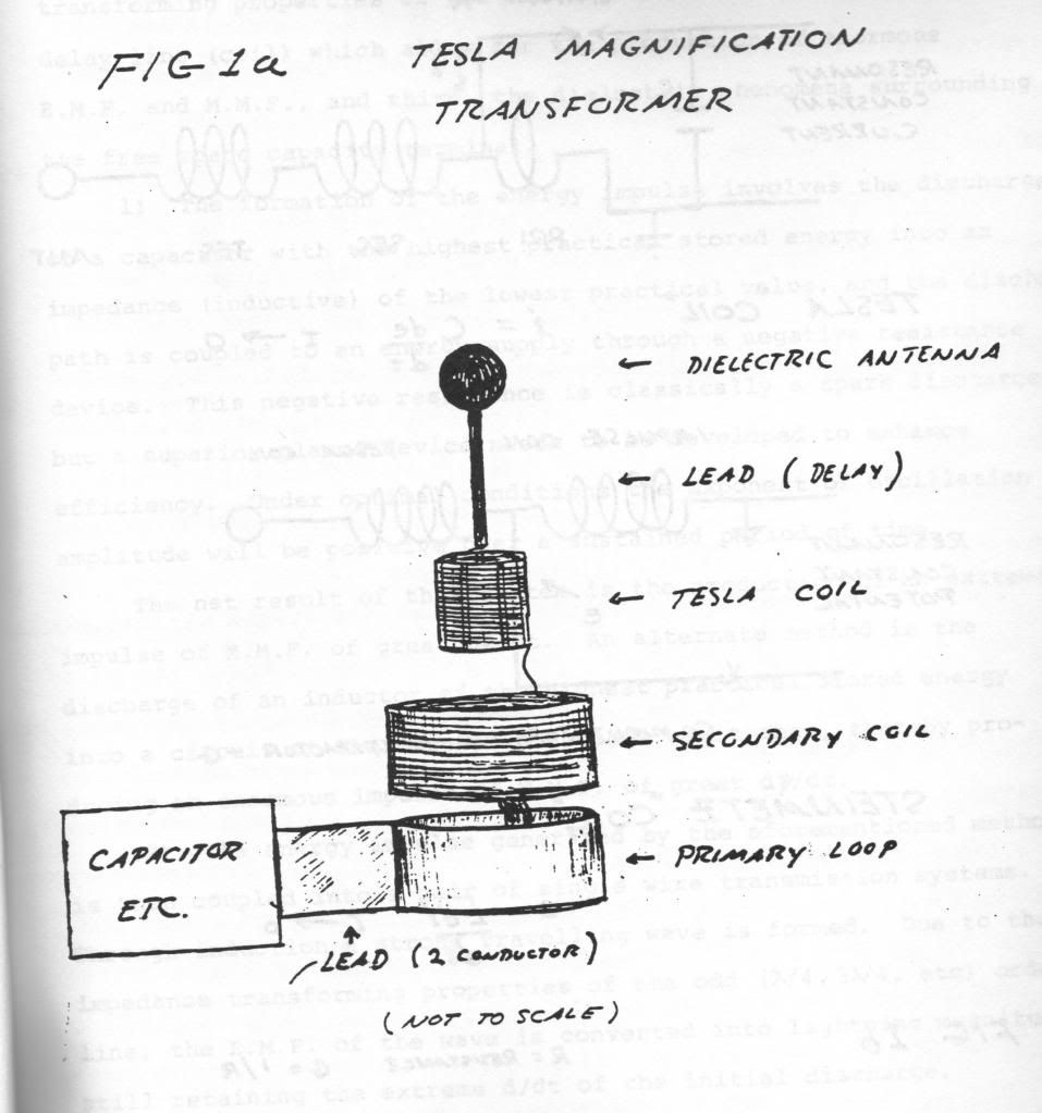
                              • In the picture of the Tesla magnification transformer
                                I can understand most of the drawing except the construction
                                of the primary loop and and how the leads are connected.
                                Also I am not sure what happens at this junction.

                                Comment

                                Working...
                                X