Announcement

Collapse
No announcement yet.

Eric Dollard

Collapse
This is a sticky topic.
X
X
 
  • Filter
  • Time
  • Show
Clear All
new posts

  • Thanks Sputins.

    If I remember well you also made flat coils. Did you use the same 62% wire spacing there in the secondary? I am thinking of making a flat coil that will not be useful with an extra coil but might make a better simple telluric system?

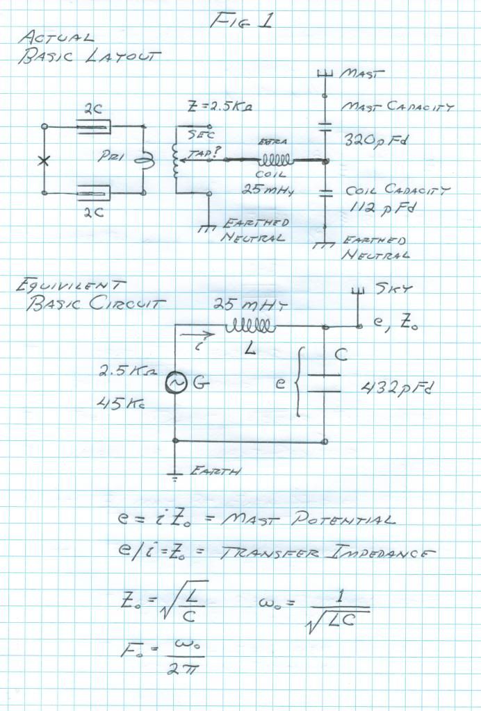
    Also I have a question about tuning the extra coil. In the original drawing Eric showed the extra coil with its elevated capacity coupled to a plate that was connected to earth. Now I wonder if the tuning was done without the extra plate. Perhaps the extra plate was tuned to resonate with the extra coil? I see no descriptions of that final tuning stage. Was the capacitor large enough etc. I wonder what drGreen did there. Perhaps we could just leave the extra plate and operate the extra coil just as an extension of the secondary coil?
    Comment


    • Originally posted by orgonaut314 View Post
      Thanks Sputins.

      If I remember well you also made flat coils. Did you use the same 62% wire spacing there in the secondary? I am thinking of making a flat coil that will not be useful with an extra coil but might make a better simple telluric system?

      Also I have a question about tuning the extra coil. In the original drawing Eric showed the extra coil with its elevated capacity coupled to a plate that was connected to earth. Now I wonder if the tuning was done without the extra plate. Perhaps the extra plate was tuned to resonate with the extra coil? I see no descriptions of that final tuning stage. Was the capacitor large enough etc. I wonder what drGreen did there. Perhaps we could just leave the extra plate and operate the extra coil just as an extension of the secondary coil?
      "Doesn't matter how many times you kick the coyote in the head, it's still gonna eat chickens". - EPD

      Comment


      • Yes thanks I now get the elevated capacity. The tuning of the extra coil is something I am hesitating on. I now have a system without extra coil with tube driver and that I understand.

        One thing on the impedance matching between tubes driver and the system with an extra coil. Perhaps the extra coil raises the impedance? I edited my calculations that where wrong. I have no idea how to calculate the impedance seen by the driver but I can measure it. It was low like 500 Ohm.

        That is another reason to try the extra coil this time.


        Picture comes from coil compendium thread.
        Last edited by orgonaut314; 05-26-2015, 09:58 AM.

        Comment


        • Z match

          Originally posted by orgonaut314 View Post
          Yes thanks I now get the elevated capacity. The tuning of the extra coil is something I am hesitating on. I now have a system without extra coil with tube driver and that I understand.

          One thing on the impedance matching between tubes driver and the system with an extra coil. Perhaps the extra coil raises the impedance? I edited my calculations that where wrong. I have no idea how to calculate the impedance seen by the driver but I can measure it. It was low like 500 Ohm.

          That is another reason to try the extra coil this time.


          Picture comes from coil compendium thread.


          So research Pi networks (ham radio), impedance matching, for some background. (Baluns, & magnetic loop antennas hold some useful info to).

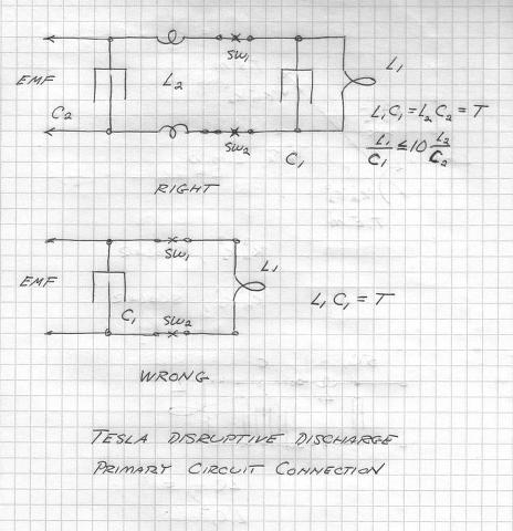
          Remember what Eric wrote:

          The Primary Circuit, First

          We begin with the "Primary Circuit." It is a parallel resonant circuit. This exists in the dimension of time, it is space scalar. Hence no T.E.M., etc. Time only in Neper-Radians per second. PER SECOND. It should be noted that no generalized analysis of this circuit even exists today, so where do YOU want to begin. I will tell you how, get a 1960's Radio Amateur's Handbook, and read it. Then make a 100 watt 80 meter transmitter. Then you can begin to understand Tesla. Throw all the Bearden, Corum, etc. , into the garbage, let the rats and crows have it.

          The circuit I have shown is from the Colorado Springs Notes, read this for circuit values, these can be scaled. The reasoning here is that no resistance is wanted in the main tank circuit (L1,C1), it must be tight against leaks to assure maximum magnification factor. The Auxilary Circuit (L2,C2) is an impedance matching network to carry energy from the supply E.M.F. to the tank circuit M.M.F. The energy in L2 C2 refracts into L1 C1 so as not to disturb the primary M.M.F. This M.M.F. the maximized to the highest possible magnitude.


          "Doesn't matter how many times you kick the coyote in the head, it's still gonna eat chickens". - EPD

          Comment


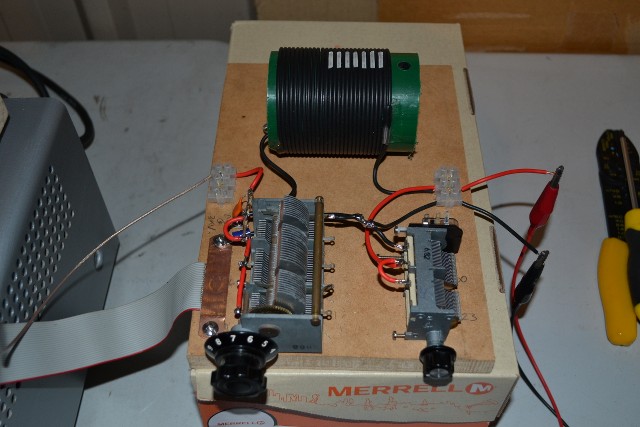
          • Nicely done and good description for everyone to try. However the resonance of the primary tank depends on the frequency so I first find the resonance of my primary with secondary and than try to develop my impedance network having a maximum at the same frequency. I use a L matching network.

            However my latest try had a resonance of the coil at 3,2MHz but with the L-network the resonance was at 2,8MHz so I think I still not have the right coil value because I adjust the cap. I have a variabel coil that I can connect to further optimise the radiation.

            My work is not as nice as yours but I am learning
            Last edited by orgonaut314; 05-27-2015, 04:16 PM.

            Comment


            • Originally posted by orgonaut314 View Post
              Nicely done and good description for everyone to try. However the resonance of the primary tank depends on the frequency so I first find the resonance of my primary with secondary and than try to develop my impedance network having a maximum at the same frequency. I use a L matching network.

              However my latest try had a resonance of the coil at 3,2MHz but with the L-network the resonance was at 2,8MHz so I think I still not have the right coil value because I adjust the cap. I have a variabel coil that I can connect to further optimise the radiation.

              My work is not as nice as yours but I am learning
              "Doesn't matter how many times you kick the coyote in the head, it's still gonna eat chickens". - EPD

              Comment


              • Thanks! Yes it is all new to me. I lost most time trying to build the tube driver.

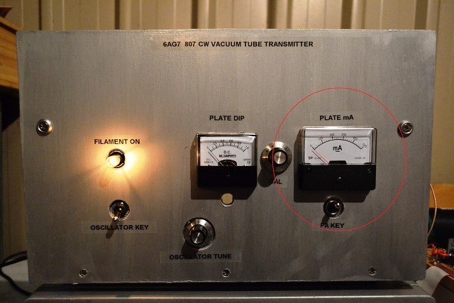
                You mentioned that the plate current was dipped at optimum load. I realised that I did not measure the plate current so I tried a mA meter between the dc power and the anode but that gave me 10mA and nothing dipped.

                So please could you help me out what current I have to measure to dip the plates?

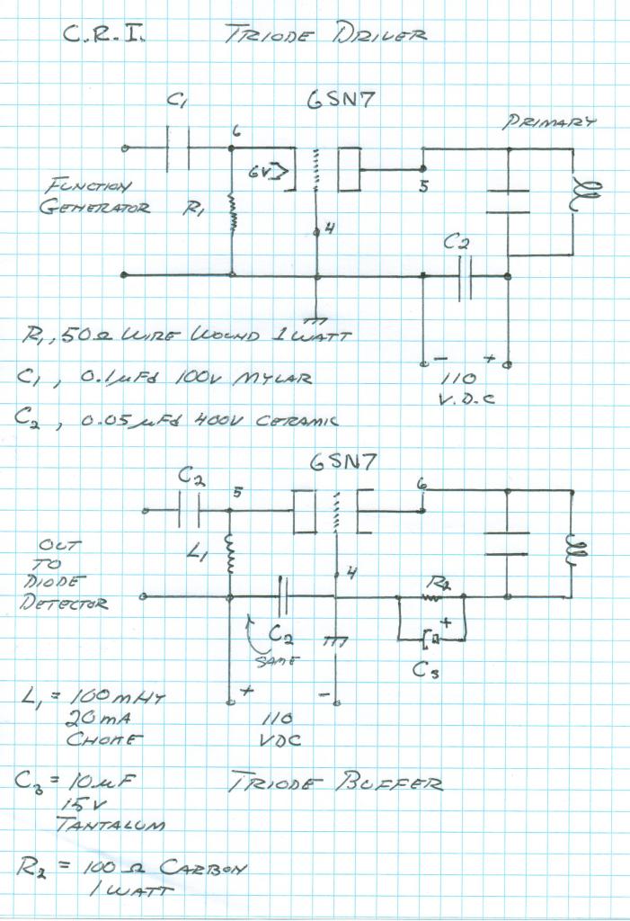
                This is my grounded grid driver.

                Last edited by orgonaut314; 05-28-2015, 02:54 PM.

                Comment


                • Originally posted by orgonaut314 View Post
                  Thanks! Yes it is all new to me. I lost most time trying to build the tube driver.

                  You mentioned that the plate current was dipped at optimum load. I realised that I did not measure the plate current so I tried a mA meter between the dc power and the anode but that gave me 10mA and nothing dipped.

                  So please could you help me out what current I have to measure to dip the plates?

                  This is my grounded grid driver.

                  "Doesn't matter how many times you kick the coyote in the head, it's still gonna eat chickens". - EPD

                  Comment


                  • Nice! I will include some meters in my driver too. I found this document that suggested how to make a pi filter with a grounded grid:


                    It says on page 10 to use the output capacitance of the tubes as the first leg of the pi. I have retuned the whole thing now and get my mu of 5 as a max again. Pi does work better this way.

                    Now my driver is still low power but what kind of voltage do you have on the pi network? I wonder how high it needs to be to get some lamps burning.

                    Comment


                    • Something else. I have read this article from Vassilatos on Tesla and he explains it very well.
                      1996--Gerry-Vassilatos--The-Broadcast-Power-of-Nicola-Tesla.pdf

                      To summarise. Tesla discovered a new type of electricity when working on impuls currents. He discovered that this new electricity was transported as a beam wireless through the ether and induced electrons in metals.
                      Vassilatos says these where all simple primary tank circuits with spark gaps. Than Tesla discovered that metal would focus the energy and he put in metal object inside the primary. Eventually he put in coils inside the primary and discovered that the voltage in the coil would raise not through magnetic induction but because the new electricity would induce higher voltages in the succeeding windings. So the voltage on the end ring of the secondary is caused by the new electricity.

                      This would also explain why the longitudional network mentioned in an earlier
                      post would have the voltage raised much above the expected voltage.

                      If true how could the world miss this new type of aether electricity?

                      Great article.

                      Comment


                      • 4 Eric Dollard Updates

                        https://www.youtube.com/watch?v=cSGbTsR6R2A

                        There are 2 days left for Eric's Seismic Indiegogo campaign - anything you can donate before it expires would help immensely. Many of you have donated by PayPal and that of course won't show up on Indiegogo but we'll be giving a final accounting of everything once the funds are received by EPD Laboratories, Inc. Please donate here now: Eric Dollard - Tesla Seismic Warning System 2.0 | Indiegogo

                        Sincerely,
                        Aaron Murakami
                        EricPDollard.com
                        Sincerely,
                        Aaron Murakami

                        Books, Videos, ESTC Conference Info, Blog, etc. https://emediapress.com

                        Comment


                        • Originally posted by Sputins View Post
                          I believe dR-Geen said the 20% height to width ratio format produced better output than the spiral coil format.
                          Greetings all. I'm currently on a camp site in France so haven't been on here but making my way home now. In the meantime, haven't read everything but as for the quote, it would also depend on primary and secondary coupling etc. It's easier to adjust on the solenoid style. And mine weren't designed using any particular considerations except the important basics. Overall solenoid is also easier to make.

                          Tuning with extra coil using Eric's design will be tricky which is why Eric recommends to just use the secondary. But tandem mode with extra coil is easy and improves performance but frequency will not match the original design. Alternatively the Colorado Springs coil can be scaled to a specific frequency for use with extra coil through keeping all the relative and relevant ratios constant.
                          http://www.teslascientific.com/

                          "Knowledge is cosmic. It does not evolve or unfold in man. Man unfolds to an awareness of it. He gradually discovers it." - Walter Russell

                          "Once men died for Truth, but now Truth dies at the hands of men." - Manly P. Hall

                          Comment


                          • When you are back perhaps you can explain how the mast capacity is used as I do not get it. Is it a LC resonance with the coils or does it just change the tandem mode 1/4 wave resonance a little as extra burden?

                            Comment


                            • Originally posted by Marcus Neuhof View Post
                              ldrancer, think about it this way. If a large earthquake suddenly comes, it might produce some billions of dollars in damages. On the other hand, if you announce "tomorrow Los Angeles will be hit by a massive earthquake, large enough to cause billions of dollars in damages" and people panic -- jam the freeways, empty the grocery stores, start riots, go on looting sprees -- then it might cause ten times as much damage! That is the ethical conundrum which the Advanced Seismic Warning System contains. Which is the correct course of action?

                              To be sure, we cannot know in advance that announcing an earthquake is *likely* will produce panic. You could therefore argue withholding the knowledge which would allow people to prepare themselves is ethically wrong, even if we believe publicizing it would trigger mass unrest. Nevertheless that is Eric Dollard's judgment to make.

                              For more on this, see https://en.wikipedia.org/wiki/Trolley_problem

                              Aaron, I think what ldrancer is objecting to, at its core, are Eric Dollard's, shall we say, antidemocratic tendencies -- his way of trusting large institutions (the government, large corporations) and speaking frequently of keeping knowledge for them (such as information about an impending earthquake) rather than making it public.

                              No doubt this is a product of his personal history. Mr. Dollard after all experienced his "golden period" (or at least he seems to view it as such) while working for the Navy, RCA, and Bell Telephone... the biggest of the big organisations in the US at the time. Nevertheless from the perspective of a member of the general public -- and I think we have all come to understand that, when the chips are down, these organisations have only their own interests at heart and certainly not ours -- this is indeed a disturbing aspect of Mr. Dollard's character.

                              The fact that the Advanced Seismic Warning System appears to be completely dependent on the US "national security" apparatus, and in turn makes Mr. Dollard dependent on the same, is unfortunately not a point in its favour.
                              alright alright. HOW SOME STATES DID NOT LEGALLY RATIFY THE 16TH AMENDMENT

                              and your using scare tactics just as the destroyers of eric dollards previous work did.

                              what your doing, by only giving it to certain people, is the same, as what they done to Tesla. thats right, putting a meter on it. Oh well let you know if the big 90 story building in front of your 30 story apartment complex might, topple over. sure sure, give us some money for it. sure sure.

                              thats a meter, the same thing they done to tesla. now everything else i said is true also.

                              panic, scare tactics, lincoln used them, and a lot of other piles of crap, running for office, in office, been in office, have and had used them.

                              whatever you think ofr yourself and dont tell me what to think. id give out a scenario, opposing you, on your think of it this statement but that would only be fighting with you which you probably live off of. ill just let others do my work, see any arguements against lincolns scare tactics he used for a fiat currency system, wrote by.. ah. give me the name ill read it tell you if its good. original work only and a site thats been on, uneditted for past not, right now.

                              see up to date information. let me just disprove y8ou real quick. building, fire alarm. ok. same concept right? whats the difference between a fire and a known to soon happen earthquake? alright nothing? so, if what you say is true, why isnt there a move right now, to remove fire alarms from buildings for?

                              Comment


                              • Elevated mast capacity

                                Originally posted by orgonaut314 View Post
                                When you are back perhaps you can explain how the mast capacity is used as I do not get it. Is it a LC resonance with the coils or does it just change the tandem mode 1/4 wave resonance a little as extra burden?
                                "Doesn't matter how many times you kick the coyote in the head, it's still gonna eat chickens". - EPD

                                Comment

                                Working...
                                X