
Nodes
dR-Green
Great work, excellent methodology, could I suggest, a ground point at an Anti-Node = 41.6378 mtrs and a ground point at an Node at 83.2756 mtrs. This would be the standing wave Node/Anti-Node locations.
ANode1 = 1 x ((299792458/1800000)/4) = 41.6378 = Min Current
Node1 = 2 x (299792458/1800000)/4) = 83.2756 = Max Current
ANode2 = 3 x (299792458/1800000)/4) = 124.9135 = Min Current
Node2 = 4 x (299792458/1800000)/4) = 166.5513 = Max Current
etc..
Regards Arto
-
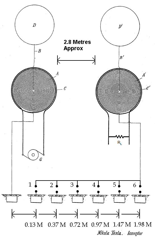
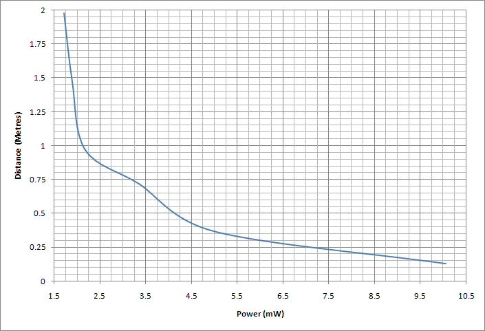
First relatively scientific experiment dealing with Telluric transmission power over distance. Nothing is really optimised; the type of capacitors on the receiver (and transmitter) make a notable difference, the (length of the) cables leading to and from the earth terminals and coils make a notable difference, and the quality of the earthing makes a notable difference in both the transmission and the reception. So seeing as none of these things have been addressed this is just for gathering some initial data. The same earth terminals as in the videos from last summer are used, 6th (furthest) terminal is about twice as deep as the others. Receiver voltage is measured across receiver load = 1k resistor. This is using the full 3 coil Colorado Springs setup, not flat spirals like the diagram shows. The receiver was quickly tuned to maximum potential at the furthest distance and then left as it was for all the tests.
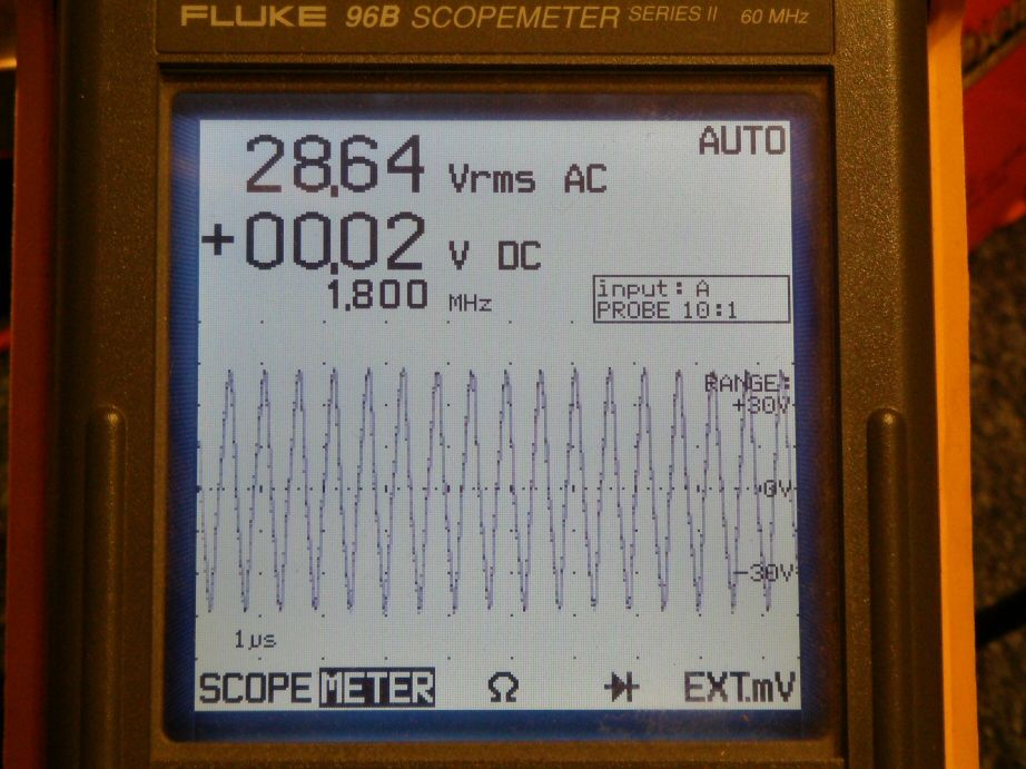
Transmitter primary voltage: The meter shows about +/-40V peak which I'm not really sure about seeing as the power supply is only +/-15V
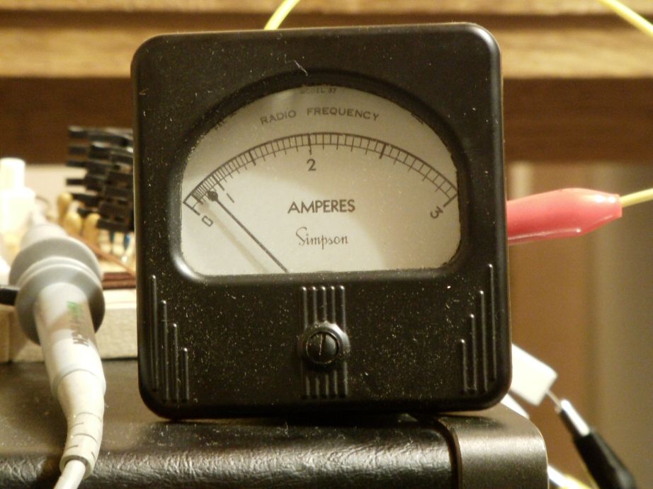
Transmitter primary current: Approx 490mA RMS
Assuming these measured values are correct, which I'm not convinced about, then the power input to the transmitter approx = 14 Watts. The transmitter power output is still unknown.
Receiver voltage
Point 1:
Power = 10mW RMS
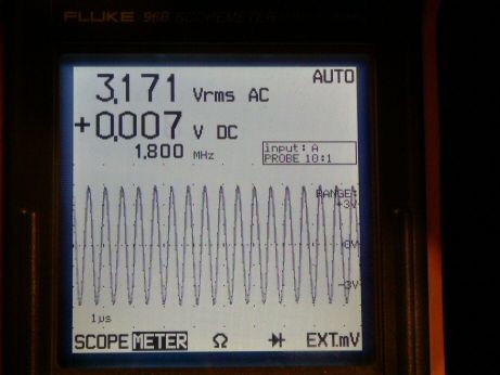
Point 2:
Power = 5mW
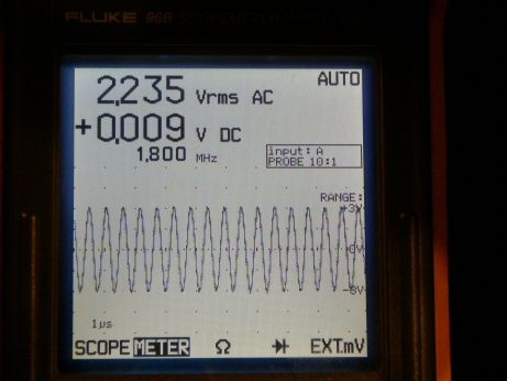
Point 3:
Power = 3.35mW
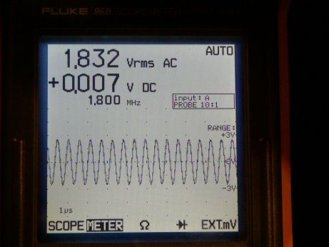
Point 4:
Power = 2.18mW
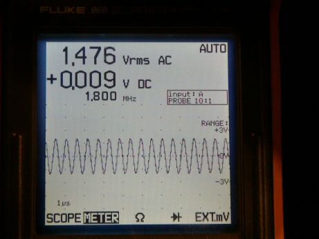
Point 5:
Power = 1.9mW

Point 6:
Power = 1.7mW
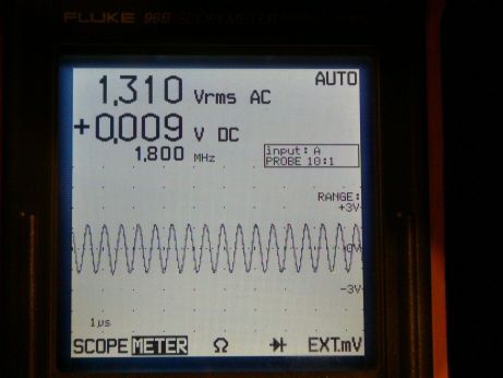
Taking the measurement at Point 2 into consideration, doubling the distance will supposedly reduce the received power to 25% the measured value. Power received at Point 2 = 5mW and distance at Point 2 = 0.37 metres, doubled = 0.74 metres. Received power at 0.74 metres therefore should supposedly be 1.2mW. However, it would seem to be the case that actual measured power at 0.72 metres = 3.35mW which is more.
Leave a comment:
-
New Image Host
Ok, here we go again!
This is what I am using, very simple, no quirks and looks ok:
Postimage.org - free image hosting / image upload
This is the modified EV Gray schematic showing the two omitted diodes.

SmokeyLeave a comment:
-
EV Gray modified schematic
Aaron,
Thanks for your response.
Post of 4th February 2011 to CSSP & Don Smith:
EV Gray like TH Moray had lots to offer but had difficulty in transferring/communicating their information for various reasons and associated with those in control:
Pulsed capacitor discharge electric engine
Go to Figure 1. and between 24 & 25 and 23 & 26, draw in two diodes, the same as 22 & 21 and in the same direction.
This is what is deliberately missing in the Patent for those that are attempting replications.
What 23 & 24 are, is a very long winding of some 10,000 ft that encircles the motor housing and is in effect, a 10uS delay line (1,000ft = 1 uSec).
This is the area where the magic happens.
Visions of my David Well's Machine and Joseph Newman where the/our 'T' field generated - must also be a 'monster' and why it can control the Weather.
This area of the machine is 'somewhere else' if you know what I mean - it is not actually here in this dimension but pulsing in and out of our time frame and the next door one - like in the movies where people step through the fuzzy doorway into another dimension.
The diodes are there to direct the capacitor bank charge through the spark gaps and not back into the delay line and also the inductive potential in the wire coil needs to go somewhere and that is directed through the diodes to the capacitor banks.
Don't think the people at EV Gray even know this.
I will scan/condition and upload the document later to both CSSP and Don Smith - some earlier scans were poor renditions and may be able to be improved.
This is from George Moonhie whose Pulse Flyback Driver I have built and use and the earlier scans.
The book - 'High Voltage and Free Enegy Devices' - I purchased from Borderlands Science back in 2002 so have no concerns in providing its information for those here.
He goes into some demonstrations which clearly show what we are after - 'quantum energy extraction'.
'It's all very simple' (quote) and shows the extra potential that a capacitor supplies from the 'ambient' and what I have been talking of for some time and probably not being able to explain fully.
(end)
I might like to change some of that but also still pretty much what I consider to be correct but the diode switching phenomena could now be added to that scenario.
Image Shack:
Got it all together and now they want money as I was going to show the modified EV Gray schematic but not until I empty the pockets again.
Anybody with another picture site that is reliable and can be used to store pictures for display here?
Thanks.
SmokeyLeave a comment:
-
If you don't have Adobe Flash, or you want to use an offline player with an EQ to improve the sound quality, use these links:Originally posted by dR-Green View Post
Leave a comment:
-
new interview
dR-Green - thanks for posting those! Been waiting for them to come out - haven't been able to listen to them yet. At first, topic was going to be number and astrology with Eric, but Cherri wanted to talk about some of the disruption. Word is - there are a LOT of people outside of these forums watching this and they're in support of Eric and are completely not buying the stories of you know who. I had no idea!Originally posted by dR-Green View PostLast edited by Aaron; 03-23-2014, 02:21 AM.Leave a comment:
-
Plasma Ignition and Ed Gray
Hi David,Originally posted by David G Dawson View Post
That is still pretty close to how I still see it.
I thought the cap discharge is accelerated. However, without the diode, cap discharge is slow into the inductor. With diode, it is faster, but most is going across a gap, which is almost a short circuit so doesn't have the type of resistances offered by a coil.
So, need to measure cap discharge speed being short circuited and then compare cap discharge over gap to see if over gap is faster than direct short. If it is faster over gap, then idea still is pretty much same. If not compared to direct short circuit, then have to rethink it a bit, but that still doesn't change the basic sequence of events of what needs to happen or the basic operating principles.
Do you have a diagram showing the diodes as you mention missing from the Gray patent? He has other things that are intentionally deceiving in it like to points of the overshoot safety gap shorted, etc...Leave a comment:
-
Geomagnetic storm's affect on power grid
There is real evidence even proof that when the flux around the earth is compressed that other electrical components show up and cause transformers to overheat. page 114: http://web.ornl.gov/sci/ees/etsd/pes...Meta-R-319.pdf[/URL]
They call this Geomagnetic Induced Current GIC. This is what is responsible for the distorted wave as distinguished from normal wave. ( finally something tangible ! )
There are GIC model derived can explain the inclusion of the other waves during the half cycle. These artifacts should give some indication of what to shoot for.
A small Transmission line or (antenna system) driven the same should be affected the same. Since this has been simulated then working back from there is possible and design criteria would be available.
Note that pure sine wave is preferred in order to isolate the GIC. A square wave and it's plentiful harmonics would complicate the composite GIC.
However the multi harmonics is useful in other tesla type devices like health. The focus here on using the GIC (solar sunspot cycle ) to develop instruments .
Hopefully it is related to telluric current.Last edited by mikrovolt; 03-23-2014, 01:58 AM.Leave a comment:
-
Interview with Eric on IntellectualRadio.com, starts in part 2.
Groovy People Radio Part 2 | intellectualradio | Bambuser
Groovy People Radio Part 3 | intellectualradio | BambuserLeave a comment:
-
Seismic Warning System
In my Markovich Folder is a sister device from Joseph B Tate and this is his 'Ambient Power Module':
Joe Tate: Ambient Power Module
However, halfway through the document you will see his US Patent 4628299 and this is for a 'Seismic Warning System Using RF Energy Monitor':
Seismic warning system using RF energy monitor
This is exactly what Eric is also doing with the telephone system and opens the door to an optional method of achieving the same result but using more of an air effect other than telluric or both.
Reading the document gives you an idea of what is required to master this device and its operation.
I am not going to debate which method is the best or most reliable but shows that the method of detection is available via various means and one may be easier and simpler than the other.
What suprised me most here was that Tate has supplied a Source Code for setting up the digital electronics.
And yes I know it is solid-state and you hate that and so too do I to a degree but it might just mean that there is more to all of this than we first imagined with the prospect of sensing a seismic event just by using a local antenna.
Something to do with the Aether interaction and it not only occurs below ground but above as well - a reflected field supressing the EM?
The Patent shows that a Radio Station signal will be reduced considerably whenever an impending seismic event is due.
The antenna used is a 'broadband, horizontal, very long monopole antenna' and this turns out to be 30 meters long and exactly what I have strung up here in a half hour.
What bothers me most here is that this is a working device via a Patent but is still not in use by the Authorities and could be built by any University Student into electronics and programming.
Bottom line here is to allow destruction and not bother to prevent it and then you go in and clean up - just how stupid is that really? - this is society today in action unfortunately.
I actually built the Tate device but was not impressed but have learnt much since that effort and will be attempting again.
Hope Eric gets to see this and would like to hear his comments.
Thanks.
SmokeyLeave a comment:
-
Markovich A-Tree
Hello Aaron,
Going to take you back some years to your Post here in 2008:
I made the Markovich Post earlier and was doing a follow up when I came across your explanation above.
My question to you is - do you have anything further to this as it pretty much meets what I already know about spark and plasma gaps?
One extra point with Edwin Gray is that there are two diodes omitted from the RHS of his schematic where the coils are located, matching the two diodes on the LHS.
This is not well known and was omitted from the Patent on purpose.
Strange just how slowly we all move on any significant finding as that was some 6 years ago.
Have put the A-Tree on my project list as it complements the 'Crystal Set Initiative' (CSI).
I purchased several switching delay lines some months back on a hunch that two electrical paths meeting after different time delays were able to produce a DC voltage and Markovitch has confirmed that observation.
Peter Markovich: Apparatus To Rectify Ether Energy (ATREE)
I don't think I have ever read such a distinct and matter-of-fact document relating to what the ether really is as in Markovich's 'II. Apparatus To Rectify Ether Energy' on Page 2.
Have added this one to the project list as it complements the 'Crystal Set Initiative' (CSI) and is based on Tesla'a Magnifying Transmitter.
All the best.
SmokeyLeave a comment:
-
Very well, I will wait to see what Eric thinks about this.
Whenever we're both available, I wouldn't mind speaking to him about it.Leave a comment:
-
Cig
John,
Many thanks for the information and pics on the CIG.
Some things to remember with respect to maintenance when dealing with vintage equipment.
Dry solder joints are a classic - most of this stuff was put together at a workbench by somebody with a soldering iron and just now and again a dry joint would appear.
Carbon resistors when subjected to age and continual heating tend to read high ohms and this will include those used as RF chokes, a resistor with a wire wrapped around.
See those connected as chokes to the anode of the 1625s, I would be checking those for correct value.
Found this out in a 1950s IT-17 Heathkit Valve Tester and wondered why I always read low from a previously tested item from someone else's tester.
Also in a Yaesu FT-901D Transceiver where the HT was low and due to 1 Watt resistors reading double what they should be - be warned!
Attention to detail here may improve your output considerable.
This would refer mainly to the 1 Watt types and higher where they are involved with Plate voltage etc.
As you found out in your own faultfinding venture (well done! and could see you were excited by the effort), contacts are always going to be a problem and most current carrying contacts like in relays will have a Silver contact.
Under load conditions the Silver will oxidise and this makes a good contact where current is concerned but aged contacts always need to be cleaned as I feel there is something else there like a vertigrease that builds up over time and needs to be removed by a wet & dry paper.
Silver degenerating back to Carbon by radiation over time - Walter Russell.
Much of this coming from using vintage Multivibrators and designing power windows for automobiles.
Think I mentioned this before but a smear of Vaseline or Petroleum Jelly on Vacuum Tube pins and bases does wonders.
Gone are the days of fun stuff like repairing those old transceivers.
Good to see you using Neons for indicators and Xenons also useful at the higher voltages at about 400v.
Also have a Neon with a fast diode connected (SF37) where your fingers and body capacitance help in the sensing.
In no-man's-land here working out the theory like Eric and about to get back into production on the CSI and reading Eric's Post #796 way back in the PWHTEPD forum on 'Crystal Sets Gone Wild'.
Looking at the 100 Watts being generated from your local Radio Station.
Have this notion that there is an option to having a huge ground plane requirement that Tesla himself was not aware of and just getting this together now.
Peter Markovich and his A-Tree (Apparatus To Rectify Ether Energy) realised how to overcome this handicap as he studied Tesla at Colorado Springs before building his device and it looks a bit like a TEM/LMD time interaction to gain the DC volts out.
Peter Markovich: Apparatus To Rectify Ether Energy (ATREE)
The Cosmic Ray Detector CRD is about to have a ding-dong bell connected as I found it most difficult to obtain a good switch using the wall phone bells and was not reliable.
Still going through all the Posts and will be back shortly.
SmokeyLeave a comment:
-
Rare find
Thanks Orgon
I am glad to hear someone give an all around low down this way. I thank you for your efforts and I am re-reading your essay on the inter-relational aspects of all these men with their wonderful contributions.
Every voice adds to our understanding of existence.
Mike
Leave a comment:

Leave a comment: