-
"Doesn't matter how many times you kick the coyote in the head, it's still gonna eat chickens". - EPD -
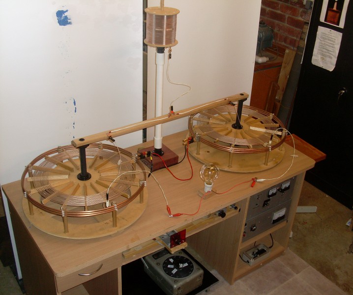
Lower shelves pull out for access:

I was considering the use of these vacuum capacitors for the main tank C. (Pulled from an old sparking VTTC, built many years ago):
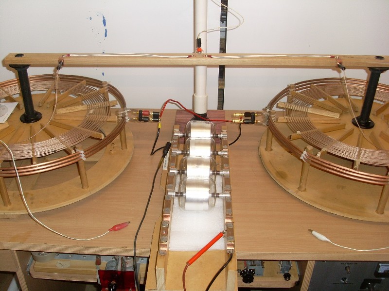
Capacitance measured with a 4262A HP LCR Meter. (Glom score for $25, normally several hundred):
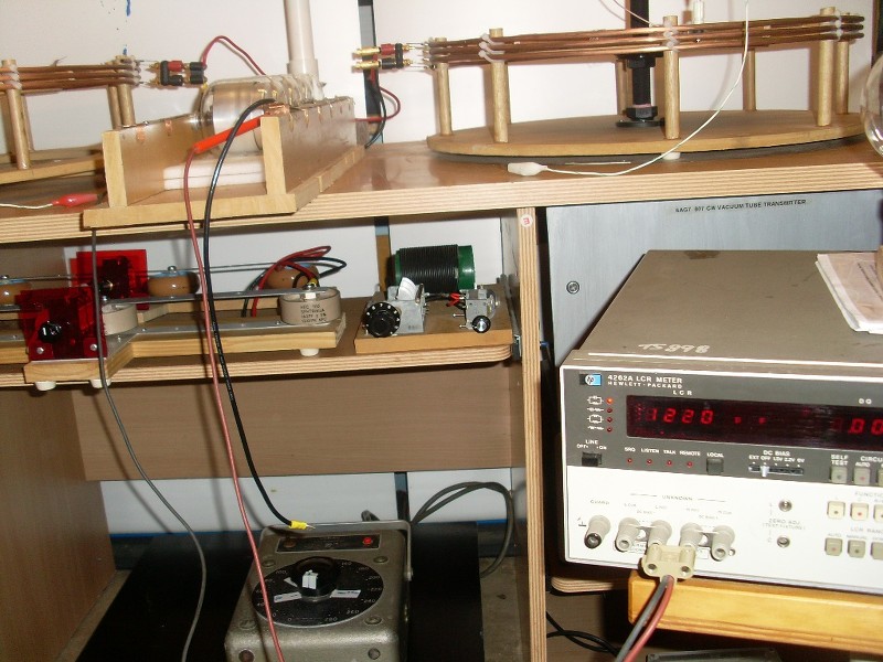
There has been further progress since the photos."Doesn't matter how many times you kick the coyote in the head, it's still gonna eat chickens". - EPDComment
-
Were you able to achieve resonance with that set up? It looks very nice. I would imagine that the extra coil would not work in that position unless both of the other ends of the secondary coils were sufficiently grounded to force the potential toward the center.Originally posted by Sputins View PostComment
-
Bucking Tesla Resonant Induction Coil
Hello,
I have finished the construction of my first bucking resonant induction coil based on the coil that was in Tesla's London lecture. I have attached the basic coil layout and circuit diagram that I got from the lecture.
It is not a true replication because I did not use gutta percha wire in beeswax impregnated paper insulation, however, I calculated that the primary and secondary are the same surface area and it is wound in the same "bucking" configuration. Based on previous math, it seems Tesla's induction coil did not keep the surface area a constant between primary and secondary, so perhaps I will rewind the secondary for more turns.
It was difficult to tune, and it is still not operating with a voltage node on the terminals of the secondary (as it should be). The main reason for this is the difficulty of tuning a spark gap system as well as the fact that the bucking coils seem to cancel out electromagnetic induction. I can not even light an LED on the secondary by scanning for resonance using a function generator @ 20vpp.
However, using the spark gap "hairpin" circuit, I was able to draw (depressingly) small sparks off of the secondary that are brilliantly white in color and very loud. This shows me that a disruptive discharge certainly gives rise to "electrostatic" effects.
The construction of my coil is as follows:
Primary - 2X 3 layers of 14 AWG, 7 turns per layer for a total of 15.5 ft and 42 turns. (25 uH)
Secondary -2X 2 layers of 24 AWG magnet wire, 26 turns per layer for a total of 55.5 ft and 104 turns
Power Source - 50kv induction coil driven by a 9v battery
The primary is wound inside the secondary as is shown in Tesla's split coil diagram. It can be seen in his diagram that he used significantly more turns then I did. I wanted to create one like this, but it is very difficult to accurately measure the length of such a long wire, especially because the coil diameter changes with each layer. Both my primary and secondary are one piece of wire in my coil, which is not easy to do when constructing a multi layered bucking coil transformer!
I will be messing around with the insulated capacitance on the secondary to see if I can get a stable and sharp resonance between the two coils. If I get any decent sparks, I will upload photos. My goal is to create a coil which exhibits biological effects like the shockwaves and heat which Tesla referred to.Attached FilesLast edited by Ajay; 01-16-2016, 04:11 PM.Comment
-
-
Originally posted by Ajay View Post"Doesn't matter how many times you kick the coyote in the head, it's still gonna eat chickens". - EPDComment
-
Sputins Extra Coil and Tuning
I would imagine the easiest way to tune the extra coil is the way which Tesla used, which is adding an insulated and elevated capacity to it. To fine tune it, I believe Tesla raised his capacity in the air until the added elevation provided enough additional capacitance to resonate the coil. May I ask what kind of power supply/circuit interrupter you are using, Sputins?
Here are some mediocre pictures of my set up. You can see the coils (which look like balls of tape) and the 50kv induction coil w/ door knob capacitors that I have been using.
I am using my laptop camera to take the pictures, so I don't want to risk having my computer near the coil while it is in operation.
The power source is currently two large 6v batteries hooked up and operating at a bout 8v and .5 amps, so there is significantly less power in the circuit than Tesla had with his high frequency alternators driving the coil.
I would like to discuss the interrupter circuits that Eric has proposed over the years and there relation to Tesla's circuits. In the paper "Condensed Intro to Tesla Transformers", he discusses multipactor and vacuum tube drive as well as a negative resistance spark gap as a means for creating the proper oscillations in the primary. In the Borderlands video, they used two hydrogen spark gaps. Eric said that "the E.M.F is much greater by the spark method" in his Condensed Intro. Tesla used various types of spark gaps at regular atmospheric pressure, he said that vacuum tubes could be used but that he "encountered other difficulties" when using them. I have been using a powerful fan to blow out the spark in my hairpin circuit just as Tesla described in the London lecture and I have found it to be extremely difficult to tune. Are there any better alternatives using modern day tech?Attached FilesLast edited by Ajay; 01-20-2016, 05:41 PM.Comment
-
-
"Doesn't matter how many times you kick the coyote in the head, it's still gonna eat chickens". - EPDComment
-
Resonance Difficulties
Thanks for all of your help, Sputins!Originally posted by Sputins View Post
I have purchased a couple of nice amps, they seem to keep breaking with the various LMD Analog networks that I have built and operated with them. I recently got a Bravo V2 vacuum tube amp, and I have no clue how to convert the audio output to two (black and red) leads! The output sounds pretty bad using headphones as well, leading me to believe it is broken
Back on the topic of the coil's resonance:
I was able to get optimal resonance using a square wave at 20vpp @ 100 khz
However, that was using a 50% duty cycle. According to this video: https://www.youtube.com/watch?v=N7gP...r_bD-QF97tCD4A the Tesla hairpin circuit outputs very sharp transient waveforms. To better replicate this effect I lowered the duty cycle to .1%, which gave me barely any light on the the ouput LED, and only at about 1khz. Anything above that frequency with the low duty cycle does not even light a single LED.
I hand wound an LMD circuit with approximately a 100khz resonance to drive the primary, but no significant advantage was gained by this. I can't light an LED with one wire connected to the LMD circuit either, so maybe that is not operating correctly.
100khz is a very high target for a spark gap operating frequency. I figured that the harmonics in a spark gap play a significant role, so if I can get a lower harmonic of 100khz, perhaps it will operate successfully. It is a wonder how Tesla tuned his coils so well back then
I am going to upgrade the spark gap a little. Any advice is greatly appreciated at this frustrating (but still fun) stage in the coil's development.
Cheers,
AjayComment
-
The stout copper bars A.K.A. "hairpin circuit" is not a resonant condition as such, it's an experiment to demonstrate, in Tesla's own words, "impedance phenomena". Standing waves related to the frequency and therefore wavelength produce high and low potential points/nodes along the bars, connecting to various points of which allowing the bulb to light up, or not.Originally posted by Ajay View Post
You will need an exceedingly high frequency in order to produce such nodes along a short length of conductor, 100 kc is much too low, the wavelength at that frequency is nearly 3000 metres. That means that the first high potential peak will be 750 metres down the line.
Also, your frequency or "trigger" source if you will is simultaneously your power supply. So if you turn the duty to 1% then of course you have less power, since the condenser is only being charged 1% of the cycle.
Ideally you need a DC or "constant" power supply, or let's say 99% duty, and then you discharge all that in 1% of the time. Not apply power to charge the condenser 1% of the time because then the amount of power in the circuit is feeble.
An LED is also not advisable, you should use small incandescent/filament bulbs starting with the 1.5V grain of wheat bulbs. Although beware that these tiny bulbs can also be more difficult to get working than higher power ones.Last edited by dR-Green; 01-23-2016, 08:28 PM.http://www.teslascientific.com/
"Knowledge is cosmic. It does not evolve or unfold in man. Man unfolds to an awareness of it. He gradually discovers it." - Walter Russell
"Once men died for Truth, but now Truth dies at the hands of men." - Manly P. HallComment
-
Hairpin
Thank you for your input dR Green. The "hairpin circuit" is just the term I used to describe the circuit. If you look at the circuit diagram I provided on a previous comment, you can see that the circuit is essentially the same, although it uses a coil instead of a "stout copper bar". Tesla recommended this circuit if the "current forming the arc is small", as it is in my case.Originally posted by dR-Green View Post
You are absolutely right about the length of the conductor being too small. I will likely need to make a larger coil and make some adjustable oil capacitors in order to fine tune the rate of charge/discharge of the capacitors in order to achieve proper resonance. It is difficult to know what the frequency limits of the spark gap are when using a disruptive discharge circuit because there is no one who has documented it.
I have also purchased some neon bulbs for use in future experiments.
Has anyone achieved HV resonance on a Tesla coil built to Eric's specs besides Eric?Comment
-
Yikes! Hopefully it cleared out safely. I suppose that's one advantage of living in a cold and wet country, at least there are no deadly creatures to worry about!
That's quite a professional looking setup you've got coming along there. Nice idea building it into the desk.http://www.teslascientific.com/
"Knowledge is cosmic. It does not evolve or unfold in man. Man unfolds to an awareness of it. He gradually discovers it." - Walter Russell
"Once men died for Truth, but now Truth dies at the hands of men." - Manly P. HallComment
-
Enormous Great White Shark Photographed In Australia Could Be Largest Ever Seen | IFLScienceOriginally posted by dR-Green View PostLast edited by Sputins; 01-25-2016, 12:20 AM."Doesn't matter how many times you kick the coyote in the head, it's still gonna eat chickens". - EPDComment
-
Great job guys, those tesla models should be will be handy.
I posted a video that shows the original coils 10 mH
The sectional type. I am not sure what he needs now.
Comment
This forum is preserved as a permanent archive. The community continues at eMedia Press.
- If this is your first visit, be sure to check out the FAQ by clicking the link above. You may have to register before you can post: click the register link above to proceed. To start viewing messages, select the forum that you want to visit from the selection below.

 Tweet
Tweet
Comment